In this tutorial, we will learn about Arduino Ethernet Shield and how to interface it with Arduino. We will learn about the working of Ethernet and how it is used with Arduino. Moreover, we will make a project using Ethernet and Arduino and will communicate over Ethernet for controlling the real-life objects.
You may also like to check how to interface esp8266 wifi module with arduino
Recommended Components
The following components are used in this project or are helpful for building it with the Arduino.
| Component | How it’s used in this project | Buy on Amazon |
|---|---|---|
| Arduino Uno R3 | The main controller board that runs the sketch and drives every component in this project. | Check Price |
| Ethernet shield | Provides wired internet connectivity so the Arduino can run a web server over Ethernet. | Check Price |
| Breadboard | Lets you build and prototype the circuit without soldering. | Check Price |
| Jumper Wires | Used to make all the connections between the Arduino, breadboard, and modules. | Check Price |
As an Amazon Associate we earn from qualifying purchases. Prices and availability are accurate as of the date/time indicated and are subject to change.
Introducing Ethernet
Traditional Ethernet supports data transfers at the rate of 10 megabits per second. As the needs evolved with time additional new Ethernet specifications have been developed by industry for Fast Ethernet and Gigabit Ethernet. Fast internet has speed up to 100Mbps and Gigabit Ethernet has speed of 1000Mbps. Ethernet cables are also prepared for specific standards. CAT 5 is the most popular cable which supports both traditional and Fast Ethernet. The CAT 5e and CAT 6 cables support Gigabit Ethernet. To connect Ethernet cables to a computer or other network device, a person plugs a cable directly into the device’s Ethernet port. Some devices without Ethernet supports can also support Ethernet connections through USB to Ethernet Adapters which are called dongles.
Working of Ethernet
Working of Ethernet is a stepwise process. Following are the steps involved in the working of internet.
- First of all, users should have Ethernet card i.e. network interface card in the computer systems it is one of main components in transmitting the data from one place to another. Generally, Ethernet is used to transmit data in the form of different data packets, so it is the main hardware component for working with Ethernet.
- Second component is the recommended networking cable for the working of the Ethernet. There are number of wires in single cable on which the transmission of data depends and these cable also enable us to transmit data in both directions.
- The final step in the working of the Ethernet is to deliver the data from one place to another. For this purpose routers are used. They direct the computers to the network and help in working to share the data across different computers.
- Connect the computers having Ethernet connection to the internet or the any networking source. In this case routers of the Ethernet connect to the modem and then send or receive data with other networked systems.
Applications
- Ethernet Layer 2 Virtual Private Networks maximize the performance of existing IT infrastructure increasing network control.
- The deterministic and dynamic service attributes of Ethernet benefit the way cloud computing is used and consumed.
- Provides added performance and higher bandwidth levels along with service standardization at all locations.
- Offers better transparency, standardization at all locations and easier performance management.
- Provides better quality of service in video applications.
- Voice over Internet Protocol is well-known for its cost-savings. Ethernet provides quality of service options and improved performance management.
- Provides added performance and higher bandwidth levels in distributed storage areas.
- Ethernet connectivity offers consistent cost and ubiquity enabling improved service management in CCTV applications.
- Ethernet allow business continuity and disaster recovery networks to optimally perform with measurable performance and flexible bandwidth levels.
- Ethernet delivers the higher bandwidth required for distributed imaging systems including picture archiving and communications system.
Introduction to Arduino Ethernet Shield
Ethernet Shield allows internet connectivity to Arduino board by using its Ethernet library. We can use this Ethernet library to write sketches (Arduino program written in IDE) that will help us to configure this shield to connect to internet. This shield is compatible with almost all versions of Arduino boards. It enables our board to receive and send data worldwide by providing it internet connection. SD card option is also available in it and we can write and read this card by using SD library. Endless amount of possibilities are provided by just allowing your project to connect to internet.
This shield relies on Wiznet W5100 chip Ethernet with internal buffer space of 16 KB. It can support up to 4 simultaneous socket connections. This chip provides a network IP stack which is capable of both transport layer protocol of internet i.e. TCP (transmission control protocol) and UDP (user datagram protocol). TCP provides more reliable service of transporting messages as compared to UDP and much more features of these 2 protocols are there but that’s not our concern in this article right now. We are simply focused on providing our board internet connectivity via this shield.
The newer version of this shield relies on W5500 Ethernet chip having 32 KB buffer size, supports auto negotiation and supports I2C , UART interface. By making use of long wire warp headers for connecting Ethernet shield to Arduino board keeps the pin layout intact and other shields can be stacked on top of it.
Requirements for Arduino Ethernet Shield
We have to plug this shield on our Arduino board but below are some mandatory requirements:
- RJ45 cable for connection to network
- Arduino board (for sure. Because this shield cannot be used as standalone project)
- Operating voltage of 5 V should be provided by Arduino board
- Make connection with Arduino board on SPI port
- Power over Ethernet module required (this module is designed for power extraction from conventional twisted pair Ethernet cable) which should meet following requirements:
- Low output noise and ripple
- Input voltage: 36 V – 57 V
- Over-load protection
- Output voltage: 9V
- The input to output isolation should be of 1500 V
- Highly efficient DC/DC converter
- 3af compliant
One important thing that is to be noted here is that both SD card and W5100 share SPI bus as Arduino communicates via SPI port so we can use only one of them. If we want to use both of them then we have to check their corresponding library.
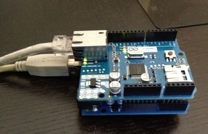
Interfacing Arduino Ethernet Shield with Arduino

Ethernet Shield comes with different pins, provided for connections. We place this shield on Arduino board properly and connect the Ethernet Port with the router providing the internet service. Note that The Ethernet shield is attached to pins 10, 11, 12, 13 so those cannot be used as general purpose input output pins.
Note: This shield is also compatible with Arduino Mega so you can also use that as well if you want to control more devices.

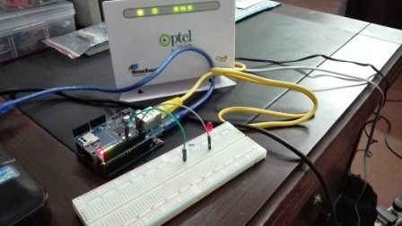
Connect the Ethernet shield with router as shown in the picture below:
Connect the Ethernet shield with router. For demonstration of Arduino Ethernet Shield, we will control an LED connected with the Arduino’s digital pin through a web server.
Hence connect the LED’s anode pin with pin 8 of Ethernet Shield through a 220 ohm current limiting resistor. Connect cathode pin of LED with GND of Ethernet Shield.
Note: In program use the IP address of your connection and if your default port is blocked by internet service provider i.e. 80 use your own. Most of the times 80 works fine.
Arduino Sketch: LED control Web Server via Ethernet
We will use Arduino IDE to program our Arduino board. Open your Arduino IDE and go to File > New to open a new file. Copy the code given below in that file and save it.
/*
  A simple web server
  Circuit:
  Ethernet shield attached to pins 10, 11, 12, 13

*/

#include <SPI.h>
#include <Ethernet.h>


// Enter a MAC address and IP address for your controller below.
byte mac[] = {0x90, 0xA2, 0xDA, 0x0D, 0x48, 0xD3 };

// The IP address will be dependent on your local network:
// assign an IP address for the controller:
IPAddress ip(192, 168, 1, 2);
IPAddress gateway(192, 168, 10, 1);
IPAddress subnet(255, 255, 255, 0);

// Initialize the Ethernet server library with the port you want to use.
EthernetServer server(80);
String readString;

// Declare Pin 8 as an LED because thats what we will be connecting the LED to.You could use any other pin and would then have to change the pin number.
int led = 8;

void setup()
{
  pinMode(led, OUTPUT); //pin selected to control
  //enable serial data print
    Serial.begin(9600);
    //start Ethernet
    Ethernet.begin(mac, ip, gateway, subnet);
    server.begin();
    Serial.print("Server is at ");
    Serial.println(Ethernet.localIP());
    Serial.println("LED Controller Test 1.0");
}

void loop()
{
    // listen for incoming clients
    EthernetClient client = server.available();
    if (client)
      {
        Serial.println("new client");
        while (client.connected())
          {
            if (client.available())
              {
                char c = client.read();
                //read char by char HTTP request
                if (readString.length() < 100)
                  {
                    //store characters to string
                    readString += c;
                    //Serial.print(c);
                    Serial.write(c);
                    // if you've gotten to the end of the line (received a newline
                    // character) and the line is blank, the http request has ended,
                    // so you can send a reply
                    //if HTTP request has ended
                    if (c == '\n') {
                        Serial.println(readString); //print to serial monitor for debuging

            // Needed to Display Site:
            client.println("HTTP/1.1 200 OK"); //send new page
                        client.println("Content-Type: text/html");
                        client.println();
                        client.println("<HTML>");
                        client.println("<HEAD>");

            // what is being Displayed :
                        client.println("<TITLE>Home Automation</TITLE>");
                         client.println("<center>");
                        client.println("</HEAD>");
                        client.println("<BODY>");
                        client.println("<H1>Home Automation Microcontrollerslab.com</H1>");
                        client.println("<hr />");
                        client.println("<center>");
                        client.println("<a href=\"/?lighton\"\">Turn On Light</a>");
                        client.println("<br />");
                        client.println("<br />");
                        client.println("<a href=\"/?lightoff\"\">Turn Off Light</a><br />");
                        client.println("</BODY>");
                        client.println("</HTML>");
                        delay(1);
                        //stopping client
                        client.stop();

                        // Code which needs to be Implemented:
                        if (readString.indexOf("?lighton") > 0) //checks for on
                          {
                            digitalWrite(8, HIGH);     // set pin 8 high
                            Serial.println("Led On");

            }
                        else {
                            if (readString.indexOf("?lightoff") > 0) //checks for off
                              {
                                digitalWrite(8, LOW);     // set pin 8 low
                                Serial.println("Led Off");

              }

            }

                        //clearing string for next read
                        readString = "";
                        // give the web browser time to receive the data
                        delay(1);
                        // close the connection:
                        client.stop();
                        Serial.println("client disonnected");

          }

        }

      }

    }

  }
}
How the Code Works?
We will start by including the necessary libraries for this project. Both the required libraries are built-in so you will not be required to install them.
#include <SPI.h>
#include <Ethernet.h>
Next specify the MAC address of the shield:
byte mac[] = {0x90, 0xA2, 0xDA, 0x0D, 0x48, 0xD3 };Assign an IP address for the controller.
IPAddress ip(192, 168, 1, 2);
IPAddress gateway(192, 168, 10, 1);
IPAddress subnet(255, 255, 255, 0);
The EthernetServer object will be used to set up the web server. We will pass the default HTTP port which is 80, as the input to the constructor. This will be the port where the server will listen to the requests.
EthernetServer server(80);The int variable ‘led’ stores the Arduino digital pin connected with the anode pin of the LED. It is pin 8 in our case.
int led = 8;setup()
Inside the setup() function, configure the led pin as an output. This is done by using the pinMode() function. Specify the pin as the first parameter and the mode as the second parameter.
pinMode(led, OUTPUT);Open the serial communication at a baud rate of 9600.
Serial.begin(9600);We will initialize the Ethernet library and the network settings using Ethernet.begin() with the Ethernet hardware address of the shield, IP address, gateway and subnet as arguments inside it.
Ethernet.begin(mac, ip, gateway, subnet);To start the server, we will call begin() on our server object. Moreover, print the IP address of the Ethernet Shield in the serial monitor.
server.begin();
Serial.print("Server is at ");
Serial.println(Ethernet.localIP());
Serial.println("LED Controller Test 1.0");
loop()
Inside the loop function, this line is used to receive a request from new web clients. If the client request is available, server.avaialble() function stores logical one value in variable client.
EthernetClient client = server.available();Now if the client request is available, start receiving data from the client and store the data in the readString and it will continue receiving data until ‘\n’ is not found which means client has disconnected.
if (client)
      {
        Serial.println("new client");
        while (client.connected())
          {
            if (client.available())
              {
                char c = client.read();
                //read char by char HTTP request
                if (readString.length() < 100)
                  {
                    //store characters to string
                    readString += c;
                    //Serial.print(c);
                    Serial.write(c);
                    // if you've gotten to the end of the line (received a newline
                    // character) and the line is blank, the http request has ended,
                    // so you can send a reply
                    //if HTTP request has ended
                    if (c == '\n') {
                        Serial.println(readString); //print to serial monitor for debuging
The following lines of code is used to display the text on the web page. You can change the text by modifying following code
client.println("HTTP/1.1 200 OK"); //send new page
                        client.println("Content-Type: text/html");
                        client.println();
                        client.println("<HTML>");
                        client.println("<HEAD>");

            // what is being Displayed :
                        client.println("<TITLE>Home Automation</TITLE>");
                         client.println("<center>");
                        client.println("</HEAD>");
                        client.println("<BODY>");
                        client.println("<H1>Home Automation Microcontrollerslab.com</H1>");
                        client.println("<hr />");
                        client.println("<center>");
                        client.println("<a href=\"/?lighton\"\">Turn On Light</a>");
                        client.println("<br />");
                        client.println("<br />");
                        client.println("<a href=\"/?lightoff\"\">Turn Off Light</a><br />");
                        client.println("</BODY>");
                        client.println("</HTML>");
                        delay(1);
                        //stopping client
                        client.stop();
Now based on the received data from the client which we stored in a string ‘readString’, we will turn the LED ON or OFF. These conditions will check if light on or light off is pressed. These lines use readString.indexof () function which checks if a specific string is available in the header or not, if available, it will turn on and turn off the digital pin using digitalWrite() function. If the user click, ‘Turn On Light,’ then the LED turns on. If the user click, ‘Turn Off Light,’ then the LED turns off.
// Code which needs to be Implemented:
if (readString.indexOf("?lighton") > 0) //checks for on
   {
    digitalWrite(8, HIGH);     // set pin 8 high
    Serial.println("Led On");

    }
else {
      if (readString.indexOf("?lightoff") > 0) //checks for off
         {
           digitalWrite(8, LOW);     // set pin 8 low
           Serial.println("Led Off");
          }
      }
Demonstration
Make sure you choose the correct board and COM port before uploading your code to the board. Go to Tools > Board and select Arduino UNO. Next, go to Tools > Port and select the appropriate port through which your board is connected.

Click on the upload button to upload the code to the board.
After you have uploaded your code to the development board, open the serial monitor and set the baud rate to 9600. In a few moments, you will receive the IP address. Type that IP address in a new web browser and the web page will open. You will see a html page which give you provision of controlling the LED.
Watch the video below:
You may also like to read:
Hello, could you help what the problem might be?
During the check, I get the following error:
Ethernet2:3:7: error: expected constructor, destructor, or type conversion before ‘Server’
In file included from D:\Arduino\_SajátProgramok\Ethernet2\Ethernet2.ino:15:0:
C:\Program Files (x86)\Arduino\hardware\arduino\avr\libraries\SPI\src/SPI.h:178:39: error: ‘SPISettings’ has not been declared
inline static void beginTransaction(SPISettings settings) {
^~~~~~~~~~~
C:\Program Files (x86)\Arduino\hardware\arduino\avr\libraries\SPI\src/SPI.h: In static member function ‘static void SPIClass::beginTransaction(int)’:
C:\Program Files (x86)\Arduino\hardware\arduino\avr\libraries\SPI\src/SPI.h:203:21: error: request for member ‘spcr’ in ‘settings’, which is of non-class type ‘int’
SPCR = settings.spcr;
^~~~
C:\Program Files (x86)\Arduino\hardware\arduino\avr\libraries\SPI\src/SPI.h:204:21: error: request for member ‘spsr’ in ‘settings’, which is of non-class type ‘int’
SPSR = settings.spsr;
^~~~
exit status 1
expected constructor, destructor, or type conversion before ‘Server’
Thank you.