In this Arduino project, we will learn how to build a voice controlled robot using Arduino and an android application. In this embedded systems project, we aim to make a 4-WD robotic car which we can control using specific voice commands through a mobile application called AMR_Voice. The application listens and sends the instruction to the Arduino board using Bluetooth and then Arduino performs the specified operation. We will program our board in such a way that the mobile application will be capable of identifying five commands which are “Stop”, ”Forward”, ”Back”, ”Left” and ”Right”.
Note: Voice recognition application is not 100% accurate. The application is sensitive to the surrounding noises. It sometimes misinterprets the voice commands given to the robot. But you can design your own application which can ignore the surroundings and can receive your own voice only.

Recommended Components
The following components are used in this project or are helpful for building it with the Arduino.
| Component | How it’s used in this project | Buy on Amazon |
|---|---|---|
| Arduino Uno R3 | The main controller board that runs the project sketch and coordinates all the connected modules. | Check Price |
| HC-05 Bluetooth Module | Receives voice command strings sent from the Android app and passes them to the Arduino over serial. | Check Price |
| DC Motor | Drives the wheels so the robot can move forward, back, left and right. | Check Price |
| L298N Motor Driver | Lets the Arduino control the speed and direction of the DC motors. | Check Price |
| Robot Chassis + Wheels Kit | Provides the frame and wheels that hold the motors, board and battery together. | Check Price |
| Breadboard | Lets you prototype and wire the circuit without soldering. | Check Price |
| Jumper Wires | Used to make the connections between the Arduino, modules and breadboard. | Check Price |
As an Amazon Associate we earn from qualifying purchases. Prices and availability are accurate as of the date/time indicated and are subject to change.
Voice Controlled Robot Project Overview
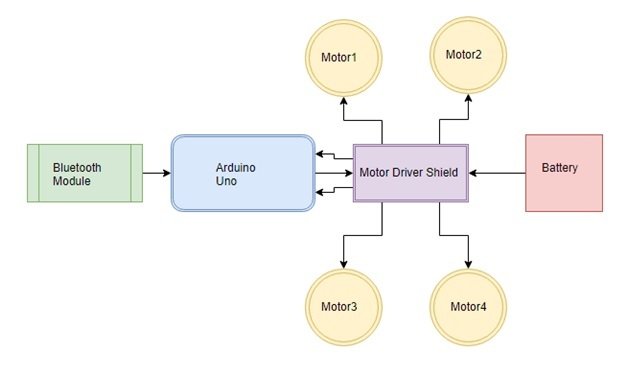
You can view the operations constituting the voice controlled robot in the block diagram below:
We will require the following hardware components to build our voice controlled robot.
Required Components:
- Arduino Uno : Arduino Uno is used because we can mount the motor driver shield in it. It is also cheap, easy to use and requires less space as we have to place everything on the chassis.
- HC-05 Bluetooth Module : This is a class-2 Bluetooth module with Serial Port Profile, which can configure as either Master or Slave. We can use it simply for a serial port replacement to establish a connection between MCU, PC to your embedded project and etc.
- L298 DC motor driver shield : The Motor Driver Shield is based on the L293 IC, which is a dual full-bridge driver. This is used to drive inductive loads such as relays, solenoids, DC and stepping motors. It lets you drive four DC motors and 2 servos with your Arduino. We can control the speed and direction of each motor independently.
- 4-WD Car Chassis : It contains 2 platforms made up of acrylic and 4 dc motors with speed encoders. It is easy to assemble and provides much space to place the Arduino board, Bluetooth module, and the battery pack.
- Battery : Each motor uses up to 200mA current. We have used three 3.7v, 2200mA Li-ion cells in parallel. The battery pack supplies 12.1 volts. Li-ion cell is a type of rechargeable battery. So we can use these cells again and again.
Recommended Reading: Arduino L293D Motor Driver Shield Control DC, Servo, and Stepper Motors
Voice Controlled Robot Working
Additionally, we will use an android smartphone that will connect to our Arduino development board. So, make sure you have an android phone at hand. Go to the Play Store and download the application by the name: AMR_Voice. Open the application and speak the specified commands to control the direction the robot moves. The application sends the command to Bluetooth which is then received by Arduino which performs the described task. Each command has its unique operations which are defined in code. You can change the commands according to your ease.
Below is the list of commands that the user will speak to control the robot.
| Command | Function |
|---|---|
| forward | The robot moves in the forward direction |
| back | The robot moves in the backward direction |
| left | The robot moves left |
| right | The robot moves right |
| stops | The robot stops |
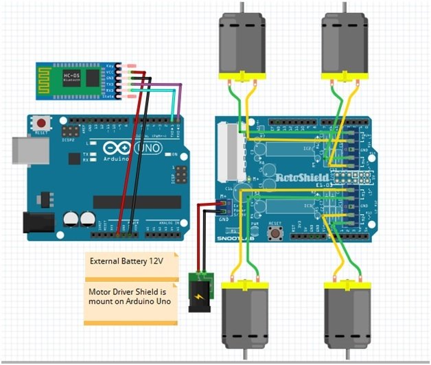
Voice Controlled Robot using L293D Motor Driver Shield diagram
Let us learn how to interface all the components together to build the voice controlled robot.
If the motor is rotating in opposite direction then swap the wire connection to rotate all motors in the same direction.
DC Motors with L293D Motor Driver Shield
The first step is to mount the L293D motor driver shield on the Arduino board. Then we will connect 4 DC motors with M1 (port 1), M2 (port 2), M3 (port 3), and M4 (port 4) terminals respectively.
- Connect Left side motors to M3 and M4 terminals.
- Connect Right side motors to M1 and M2 terminals.
We are using TT DC gear motors for this project. They require an operating voltage of 3-12V DC where the recommended operating voltage is 3-6V DC. Connect the positive terminal of power supply with +M terminal and negative terminal with GND terminal found at the EXT_PWR terminal block on the shield. Also, the power jumper is removed from the shield.
Arduino with HC-05 Bluetooth Module
The HC-05 comes with multiple pins and indicators, which helps to control different operations and view their states through indicators. This pinout diagram provides indications of all pins.
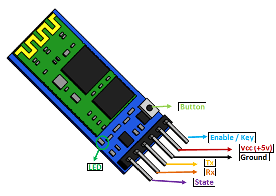
However, we will use 4 of these pins to connect with Arduino. These include the VCC, GND, RX, and TX pins.
The connection of the HC-05 Bluetooth module with Arduino UNO is very easy as we will be using the serial communication interface that consists of two pins TX and RX. As you know, in order to communicate with the HC-05 Bluetooth module, we need to use a UART communication port of the Arduino board.
RX and TX pins of the module will be connected with the UART pins of Arduino UNO. Arduino Uno has a single UART interface found on pin 0 (RX0) and pin 1 (TX0).
The table below shows the connections that we will use to connect the two devices:
| HC-05 | Arduino UNO |
| VCC | 5V |
| GND | GND |
| TX | pin 0 (RX) |
| RX | pin1 (TX) |
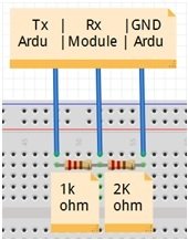
If the Bluetooth module does not work make voltage divider using a 1K and 2K resistors and connect to Rx pin of the module to convert 5v to 3.3v.
Note: Always disconnect the Rx and Tx pins of Bluetooth module when uploading code to Arduino otherwise it shows some errors and the code does not upload.
Recommended Reading: HC-05 Bluetooth Module Interfacing with Arduino with LED Control Example
Voice Controlled Robot using Arduino L293D Motor Driver Shield and HC-05
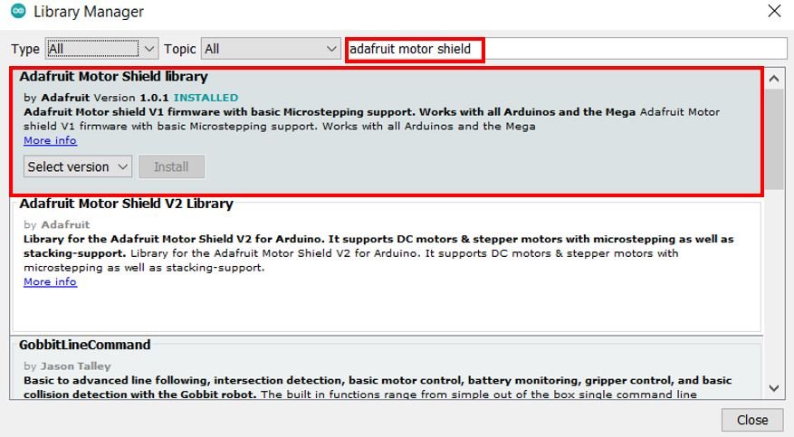
For this project, we will require the Motor Shield Library by Adafruit present in Arduino Library Manager to control the motors with our Arduino L293D motor shield. This library will provide us with useful functions to set the speed and change the direction of rotation.
To install the library, we will use the Arduino Library Manager. Open your Arduino IDE and go to Sketch > Include Libraries > Manage Libraries. Type ‘adafruit motor shield’ in the search bar and install the latest version.
Voice Controlled Robot Arduino Code
Open your Arduino IDE and go to File > New. A new file will open. Copy the code given below in that file and save it.
#include<AFMotor.h>

AF_DCMotor motor1(1, MOTOR12_1KHZ);
AF_DCMotor motor2(2, MOTOR12_1KHZ);
AF_DCMotor motor3(3, MOTOR12_1KHZ);
AF_DCMotor motor4(4, MOTOR12_1KHZ);

int tx = 1;
int rx = 0;

char inSerial[15];
char command;

void setup()
{
  Serial.begin(9600); //Set the baud rate to your Bluetooth module.
}

void loop() {

  int i = 0;
  int m = 0;
  delay(500);
  if (Serial.available() > 0) {
    while (Serial.available() > 0) {
      inSerial[i] = Serial.read();
      i++;
    }
    inSerial[i] = '\0';
    Check_Protocol(inSerial);
  }
}

void Check_Protocol(char inStr[]) {
  int i = 0;
  int m = 0;
  Serial.println(inStr);

  if (!strcmp(inStr, "*forward#")) {
    forward();
    delay(1200);
    Stop();
    for (m = 0; m < 11; m++) {
      inStr[m] = 0;
    }
    i = 0;
  }

  if (!strcmp(inStr, "*back#")) {
    back();
    delay(1200);
    Stop();
    for (m = 0; m < 11; m++) {
      inStr[m] = 0;
    }
    i = 0;
  }

  if (!strcmp(inStr, "*left#")) {
    left();
    delay(350);
    Stop();
    for (m = 0; m < 11; m++) {
      inStr[m] = 0;
    }
    i = 0;
  }
  if (!strcmp(inStr, "*right#")) {
    right();
    delay(350);
    Stop();
    for (m = 0; m < 11; m++) {
      inStr[m] = 0;
    }
    i = 0;
  }

  if (!strcmp(inStr, "*stop#")) {
    Stop();
    for (m = 0; m < 11; m++) {
      inStr[m] = 0;
    }
    i = 0;
  }

  else {
    for (m = 0; m < 11; m++) {
      inStr[m] = 0;
    }
    i = 0;

  }
}

void forward()
{
  motor1.setSpeed(255);
  motor1.run(FORWARD);
  motor2.setSpeed(255);
  motor2.run(FORWARD);
  motor3.setSpeed(255);
  motor3.run(FORWARD);
  motor4.setSpeed(255);
  motor4.run(FORWARD);
}

void back()
{
  motor1.setSpeed(255);
  motor1.run(BACKWARD);
  motor2.setSpeed(255);
  motor2.run(BACKWARD);
  motor3.setSpeed(255);
  motor3.run(BACKWARD);
  motor4.setSpeed(255);
  motor4.run(BACKWARD);
}

void left()
{
  motor1.setSpeed(255);
  motor1.run(FORWARD);
  motor2.setSpeed(255);
  motor2.run(FORWARD);
  motor3.setSpeed(0);
  motor3.run(RELEASE);
  motor4.setSpeed(0);
  motor4.run(RELEASE);
}

void right()
{
  motor1.setSpeed(0);
  motor1.run(RELEASE);
  motor2.setSpeed(0);
  motor2.run(RELEASE);
  motor3.setSpeed(255);
  motor3.run(FORWARD);
  motor4.setSpeed(255);
  motor4.run(FORWARD);
}

void Stop()
{
  motor1.setSpeed(0);
  motor1.run(RELEASE);
  motor2.setSpeed(0);
  motor2.run(RELEASE);
  motor3.setSpeed(0);
  motor3.run(RELEASE);
  motor4.setSpeed(0);
  motor4.run(RELEASE);
}
How does the Code Works?
Firstly, we will include the AFMotor.h library. This library provides useful functions that make it easy to control the motors using Arduino.
#include <AFMotor.h>Next we will create four instances of AF_DCMotor called motor1, motor2, motor3 and motor4 for the 4 DC motors connected with the shield. We will specify the motor port we are connecting our motor with as the first parameter and the PWM frequency as the second parameter.
AF_DCMotor motor1(1, MOTOR12_1KHZ);
AF_DCMotor motor2(2, MOTOR12_1KHZ);
AF_DCMotor motor3(3, MOTOR12_1KHZ);
AF_DCMotor motor4(4, MOTOR12_1KHZ);
Moreover, also specify the Arduino digital pins connected with TX and RX pins of the HC-05 module.
int tx = 1;
int rx = 0;
Also, we create an array of 15 characters called inSerial that we will use later on in the code to monitor the robot motion.
char inSerial[15];
Inside the setup() function, open the serial communication at a baud rate of 9600.
void setup()
{
  Serial.begin(9600); //Set the baud rate to your Bluetooth module.
}
loop()
Inside the infinite loop() we first check if serial data is available in the buffer. If data is found then the characters are added one by one to the array ‘inSerial’ using a while loop. Then we will call the Check_Protocol() function with ‘inSerial’ as an argument inside it. This function will be responsible for controlling the robot’s motion by comparing the received data with predefined strings.
void loop() {

  int i = 0;
  int m = 0;
  delay(500);
  if (Serial.available() > 0) {
    while (Serial.available() > 0) {
      inSerial[i] = Serial.read();
      i++;
    }
    inSerial[i] = '\0';
    Check_Protocol(inSerial);
  }
}
Check_Protocol(char inStr[])
The Check_Protocol() function takes in an array of characters as an argument inside it.
This function is responsible for controlling the robot’s movement by comparing the strings received in the buffer with a predefined string.
- In the first case, if the command ‘forward’ was spoken, then the forward() function will be called first and then after a delay the stop() function will be called.
- If the command ‘back’ was spoken, then the back() function will be called first and then after a delay the stop() function will be called.
- Likewise, if the command ‘left’ was spoken, then the left() function will be called first and then after a delay the stop() function will be called.
- Likewise, if the command ‘right’ was spoken, then the right() function will be called first and then after a delay the stop() function will be called.
- Similarly, if the command ‘stop’ was spoken, then the stop() function will be called.
void Check_Protocol(char inStr[]) {
  int i = 0;
  int m = 0;
  Serial.println(inStr);

  if (!strcmp(inStr, "*forward#")) {
    forward();
    delay(1200);
    Stop();
    for (m = 0; m < 11; m++) {
      inStr[m] = 0;
    }
    i = 0;
  }

  if (!strcmp(inStr, "*back#")) {
    back();
    delay(1200);
    Stop();
    for (m = 0; m < 11; m++) {
      inStr[m] = 0;
    }
    i = 0;
  }

  if (!strcmp(inStr, "*left#")) {
    left();
    delay(350);
    Stop();
    for (m = 0; m < 11; m++) {
      inStr[m] = 0;
    }
    i = 0;
  }
  if (!strcmp(inStr, "*right#")) {
    right();
    delay(350);
    Stop();
    for (m = 0; m < 11; m++) {
      inStr[m] = 0;
    }
    i = 0;
  }

  if (!strcmp(inStr, "*stop#")) {
    Stop();
    for (m = 0; m < 11; m++) {
      inStr[m] = 0;
    }
    i = 0;
  }

  else {
    for (m = 0; m < 11; m++) {
      inStr[m] = 0;
    }
    i = 0;

  }
}
forward()
The forward() function will be responsible for moving the robot in the forward direction. We will use the run() method on the motor instances with ‘FORWARD’ as an argument inside it to move all the motors in the forward direction. Moreover, we also set the speed of all the motors by using the setSpeed() method on the motor instances. Here we are passing 255 as a parameter inside it. Valid parameters include 0-255 where 255 is the highest speed.
void forward()
{
  motor1.setSpeed(255);
  motor1.run(FORWARD);
  motor2.setSpeed(255);
  motor2.run(FORWARD);
  motor3.setSpeed(255);
  motor3.run(FORWARD);
  motor4.setSpeed(255);
  motor4.run(FORWARD);
}
back()
The back() function will be responsible for moving the robot in the backward direction. We will use the run() method on the motor instances with ‘BACKWARD’ as an argument inside it to move all the motors in the backward direction. Moreover, we also set the speed of all the motors by using the setSpeed() method on the motor instances. Here we are passing 255 as a parameter inside it. Valid parameters include 0-255 where 255 is the highest speed.
void back()
{
  motor1.setSpeed(255);
  motor1.run(BACKWARD);
  motor2.setSpeed(255);
  motor2.run(BACKWARD);
  motor3.setSpeed(255);
  motor3.run(BACKWARD);
  motor4.setSpeed(255);
  motor4.run(BACKWARD);
}
left()
The left() function will move the robot to the left direction. This is done by moving the right side motors in a forward direction with maximum speed and stopping the left side motors. Note that we connected left side motors to M3/M4 terminals and right side motors to M1/M2 terminals.
void left()
{
  motor1.setSpeed(255);
  motor1.run(FORWARD);
  motor2.setSpeed(255);
  motor2.run(FORWARD);
  motor3.setSpeed(0);
  motor3.run(RELEASE);
  motor4.setSpeed(0);
  motor4.run(RELEASE);
}
right()
The right() function will move the robot to the right direction. This is done by moving the left side motors in a forward direction with maximum speed and stopping the right side motors. Note that we connected left side motors to M3/M4 terminals and right side motors to M1/M2 terminals.
void right()
{
  motor1.setSpeed(0);
  motor1.run(RELEASE);
  motor2.setSpeed(0);
  motor2.run(RELEASE);
  motor3.setSpeed(255);
  motor3.run(FORWARD);
  motor4.setSpeed(255);
  motor4.run(FORWARD);
}
Stop()
The Stop() function will be used to stop the robot. We will use the run() method on the motor instances with ‘RELEASE’ as an argument inside it to stop all the motors. The speed is also set to 0 in this case.
void Stop()
{
  motor1.setSpeed(0);
  motor1.run(RELEASE);
  motor2.setSpeed(0);
  motor2.run(RELEASE);
  motor3.setSpeed(0);
  motor3.run(RELEASE);
  motor4.setSpeed(0);
  motor4.run(RELEASE);
}
Voice Controlled Robot Demonstration
To see the demonstration of the above code, upload the code to Arduino. Before uploading the code, make sure to select Arduino UNO from Tools > Board.

Also, select the correct COM port to which the Arduino board is connected from Tools > Port.
After you have uploaded your code to the development board, open the application and connect it to the Bluetooth module. Try “1234” or “0000” for the password when you connect Bluetooth module with your mobile for the first time.
Now speak an appropriate command as defined in the code. When we speak the specified commands the application sends the instruction to the Arduino through Bluetooth and then Arduino performs the defined operation. The robot will start moving accordingly.
Watch the video demonstration below:
Note: Although it is fun to control a robot using voice commands but it is not an efficient way.
You may also like to read:
Voice controlled robot using aurdino uno by using voice recognition app
Voice controlled robot using aurdino uno by using voice recognition app send your number
Sir using two motor voice control robot ka circuit diagram and working send or upload plz
It is good Project.I was start to do it, but it can’t be work for me. please help me …..,send code for me…..
Sir can you send me that how to upload the code for four wheeled
Good, I am doing the assembly of the voice controlled robot with my granddaughters but it does not give us failures at the time of loading the program it gives me errors at the end of the program.
Thank you very much in advance
In file included from C:\Users\sanjeev\OneDrive\Documents\Arduino\voice_control_2\control\control.ino:1:
C:\Users\sanjeev\OneDrive\Documents\Arduino\libraries\Adafruit-Motor-Shield-library-master/AFMotor.h:156:47: error: ‘DC_MOTOR_PWM_RATE’ was not declared in this scope
156 | AF_DCMotor(uint8_t motornum, uint8_t freq = DC_MOTOR_PWM_RATE);
| ^~~~~~~~~~~~~~~~~
control:3:22: error: ‘MOTOR12_1KHZ’ was not declared in this scope
3 | AF_DCMotor motor1(1, MOTOR12_1KHZ);
| ^~~~~~~~~~~~
control:4:22: error: ‘MOTOR12_1KHZ’ was not declared in this scope
4 | AF_DCMotor motor2(2, MOTOR12_1KHZ);
| ^~~~~~~~~~~~
control:5:22: error: ‘MOTOR12_1KHZ’ was not declared in this scope
5 | AF_DCMotor motor3(3, MOTOR12_1KHZ);
| ^~~~~~~~~~~~
control:6:22: error: ‘MOTOR12_1KHZ’ was not declared in this scope
6 | AF_DCMotor motor4(4, MOTOR12_1KHZ);
| ^~~~~~~~~~~~
exit status 1
‘MOTOR12_1KHZ’ was not declared in this scope
I run the code but the some of the error was came during compile.
What is Voice Recognition app icon.