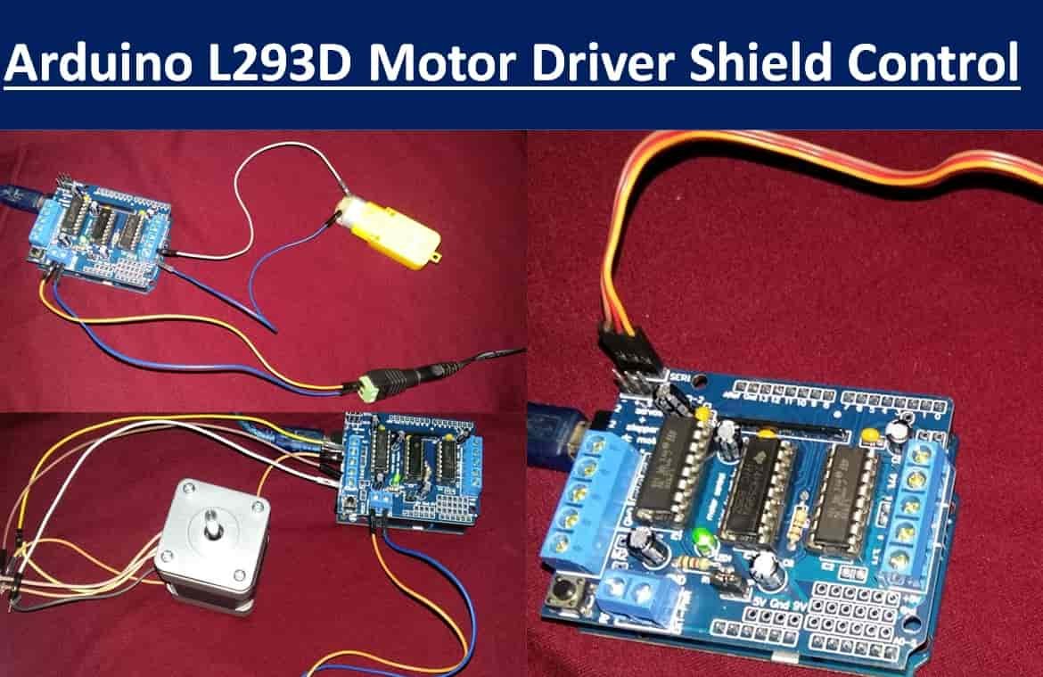
In this user guide, we will learn about the L293D motor driver shield for Arduino. This driver shield is able to drive 4 dc motors, 2 unipolar/bipolar stepper motors, or 2 servo motors simultaneously. This guide will focus on all these types of motors and how to use L293D motor driver shield with Arduino to easily drive and control their speed and direction of rotation of motors.
We have a similar guide with DRV8825 stepper motor module:
In this tutorial, we will see the following examples using L293D motor driver shield:
- DC Motor
- NEMA17 Stepper Motor
- Servo Motor
Recommended Components
The following components are used in this project or are helpful for building it with the Arduino.
| Component | How it’s used in this project | Buy on Amazon |
|---|---|---|
| Arduino Uno R3 | Hosts the L293D motor driver shield and runs the AFMotor sketch controlling DC, servo and stepper motors. | Check Price |
| Breadboard | Useful for additional connections and powering external components alongside the shield. | Check Price |
| Jumper Wires | Connect external power and motor leads to the shield terminals. | Check Price |
| DC motor | A DC motor driven for speed and direction control through the L293D shield. | Check Price |
| Servo motor (SG90) | An SG90 servo connected to the shield’s servo header and positioned from the sketch. | Check Price |
| Bipolar stepper motor (NEMA) | A bipolar stepper motor stepped through the shield’s motor channels. | Check Price |
As an Amazon Associate we earn from qualifying purchases. Prices and availability are accurate as of the date/time indicated and are subject to change.
L293D Motor Driver Shield
L293D motor driver shield is a great option to drive several motors using Arduino and used in projects such as four-wheeled robots, CNC machines, and printers. Let us see what makes this motor driver shield such a suitable option.
L293D Motor Driver Shield’s Integrated Circuit
The L293D motor driver shield features two L293D motor driver ICs and one eight-bit shift register chip.
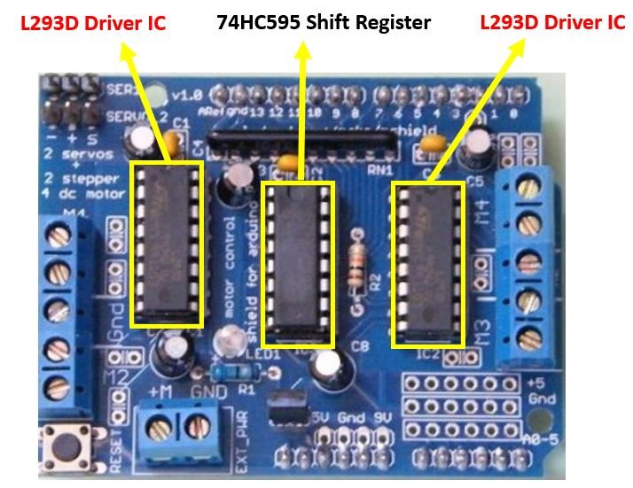
L293D IC is known as a motor driver. It is a low voltage operating device like other ICs. L293D provides a continuous bidirectional Direct Current to the Motor. The Polarity of current can change at any time without affecting the whole IC or any other device in the circuit. L293D has an internal H-bridge installed that can operate two DC motors or a single stepper motor. So as the motor driver shield consists of two L293D ICs hence 4 DC motors or 2 stepper motors can easily be controlled by this driver.
For more information about L293D IC we have a dedicated tutorial related to it: L293D Motor Driver IC introduction, pinouts and how to use
The 74HC595 is a serial-in and parallel-out shift register IC. We can use shift registers such as 74HC595 to save microcontrollers pins. The shift register controls several outputs simultaneously. Using serial in parallel out protocol, it obtains data serially from the Arduino board and transmits it through the parallel pins.
Motor Connections
The figure below shows all the motor connections present in the L293D Motor Driver Shield.

Two servo motors, Four DC Motors and Two stepper motor connections can be found on this motor driver shield. At the top left corner you can view two three pin headers. You will be able to connect two servo motors at these terminals as a single servo motor comes with three wires that need to be connected. At both the left and right sides you can view five pin terminals. We will be able to connect four DC motors rated at 4.5-25 V at these terminals. These are labelled M1, M2, M3 and M4. Additionally, we can also connect two unipolar/bipolar stepper motors at these terminals instead. The M1,M2 terminals will connect stepper motor 1 and M3,M4 will connect stepper motor 2. If using a unipolar stepper motor the GND terminals will be connected to the centre taps of the stepper motors.
One important point to note here is that this driver shield supports motors with voltages between 4.5-25V only. The maximum current will be 1.2A.
Power Supply Connections
Now let us discuss another important aspect which is the power supply connections and considerations. There are different ways we cam power both the driver shield and the motors.
- If using motors within 12V you can use a single DC power supply for both the motor driver and the Arduino. Power the driver shield using the the Arduino DC Jack. Another way could be using the external power terminals of the driver shield as well. But make sure the power selection jumper is placed on the shield.
- A more feasible way will be to use separate power supplies for both the microcontroller and the motor driver shield. First make sure the power jumper is removed. Then power the Arduino through its USB and the motor shield through an external DC power supply connected at the power supply terminals present on the shield. Moreover, you can even use two different external DC power supplies to power the motors as well as the Arduino board.
Note: If using the external power supply terminals on the driver shield, make sure the power selection jumper is removed from the shield.
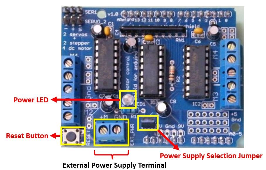
The L293D Motor Driver Shield also features a power LED that glows when the motors are properly powered on. This gives an indication that the motor power supply is correct. Additionally, you can also view a Reset button on the shield which has the same feature as the Arduino reset button.
Controlling DC, Stepper and Servo Motors using Arduino L293D Motor Driver Shield
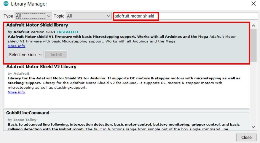
We will require the Motor Shield Library by Adafruit present in Arduino Library Manager to control all the three kinds of motors with our Arduino L293D motor shield. This library will provide us with useful functions to set the speed and change the direction of rotation.
To install the library, we will use the Arduino Library Manager. Open your Arduino IDE and go to Sketch > Include Libraries > Manage Libraries. Type ‘adafruit motor shield’ in the search bar and install the latest version.
Controlling DC Motors with L293D Motor Driver Shield with Arduino
After knowing a bit about the L293D motor driver shield let us learn how to drive and control dc motors using this shield.
Required Equipment
- Arduino
- L283D Motor driver shield
- External power supply
- DC Motor
- Connecting Wires
Assemble the circuit as shown in the connection diagram below.
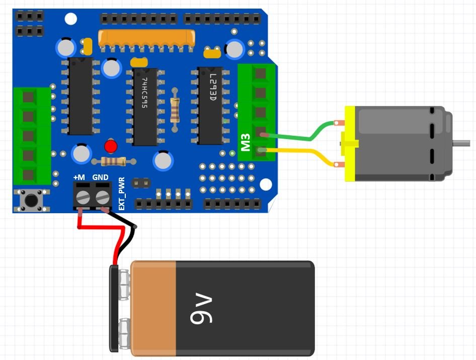
The first step is to mount the L293D motor driver shield on the Arduino board. Then we will connect a DC motor with either M1 (port 1), M2 (port 2), M3 (port 3) and M4 (port 4) terminals. We have chosen to connect our dc motor at M3.
We are using TT DC gear motors for this project. They require an operating voltage of 3-12V DC where the recommended operating voltage is 3-6V DC. Connect positive terminal of power supply with +M terminal and negative terminal with GND terminal found at the EXT_PWR terminal block on the shield. Also the power jumper is removed from the shield.

Arduino Sketch Controlling DC Motor
Open your Arduino IDE and go to File > New. A new file will open. Copy the code given below in that file and save it.
This basic sketch will show us how to control a DC motor’s speed and direction of rotation using the L293D motor driver shield with the AFMotor.h library.
#include <AFMotor.h>

AF_DCMotor motor(3);

void setup()
{
  motor.setSpeed(100);
  motor.run(RELEASE);
}

void loop()
{
  uint8_t i;

//Motor spinning clockwise
  motor.run(FORWARD);
  //Speed up
  for (i=0; i<255; i++)
  {
    motor.setSpeed(i);
    delay(10);
  }

  // Speed down
  for (i=255; i!=0; i--)
  {
    motor.setSpeed(i);
    delay(10);
  }

//Motor spinning anti-clockwise
  motor.run(BACKWARD);

  // Speed up
  for (i=0; i<255; i++)
  {
    motor.setSpeed(i);
    delay(10);
  }

  // Speed down
  for (i=255; i!=0; i--)
  {
    motor.setSpeed(i);
    delay(10);
  }

  // Now turn off motor
  motor.run(RELEASE);
  delay(1000);
}
How the Code Works?
Firstly, we will include the AFMotor.h library. This library provides useful functions that make it easy to control the motors using Arduino.
#include <AFMotor.h>Next we will create an instance of AF_DCMotor called motor and specify the motor port we are connecting our motor with. In our case we connected the dc motor with M3 hence ‘3’ is specified as the parameter inside it.
AF_DCMotor motor(3);Inside the setup() function, we will use the setSpeed() method on the motor instance and pass the speed of the motor as an argument inside it. The speed of the motor can take values from 0-255. We have set it to 100. Additionally, we will use the run() method on the motor instance with ‘RELEASE’ as an argument inside it to stop the motor. This is because initially the motor will not move.
void setup()
{
  motor.setSpeed(100);
  motor.run(RELEASE);
}
The run() method is used to set the mode of the motor. It can take in three arguments: RELEASE (stops the motor), FORWARD (motor moves in the forward direction), BACKWARD (motor moves in the backward direction).
loop()
Inside the loop() function we will first rotate the motor in forward direction where it will first speed up and then speed down using a for loop. Then the motor will rotate in the opposite direction by first speeding up and then slowing down. Then the motor stops and after a delay of 1 second the loop starts again.
void loop()
{
  uint8_t i;

//Motor spinning clockwise
  motor.run(FORWARD);
  //Speed up
  for (i=0; i<255; i++)
  {
    motor.setSpeed(i);
    delay(10);
  }

  // Speed down
  for (i=255; i!=0; i--)
  {
    motor.setSpeed(i);
    delay(10);
  }

//Motor spinning anti-clockwise
  motor.run(BACKWARD);

  // Speed up
  for (i=0; i<255; i++)
  {
    motor.setSpeed(i);
    delay(10);
  }

  // Speed down
  for (i=255; i!=0; i--)
  {
    motor.setSpeed(i);
    delay(10);
  }

  // Now turn off motor
  motor.run(RELEASE);
  delay(1000);
}
Demonstration
To see the demonstration of the above code, upload the code to Arduino. Before uploading the code, make sure to select Arduino UNO from Tools > Board.

Also, select the correct COM port to which the Arduino board is connected from Tools > Port.
Once the code is uploaded to your board, the motor will start rotating.
First, the motor will start rotating forwards, the motor start speeding up and reach maximum speed then it starts slowing down and finally stops then it starts rotating backwards, speeds up and reaches maximum speed then it starts slowing down and finally stops. After a delay of 1 second the loop starts again.
Watch the video demonstration below:
Controlling Stepper Motors (Unipolar & Bipolar) with L293D Motor Driver Shield with Arduino
We will require the following equipment.
Required Equipment :
- Arduino
- L283D Motor driver shield
- 28BYJ-48 stepper motor (unipolar) or NEMA 17 stepper motor (bipolar)
- External Power Supply
- Connecting Wires
For 28BYJ-48 stepper motor (unipolar)
Assemble the circuit as shown in the connection diagram below.
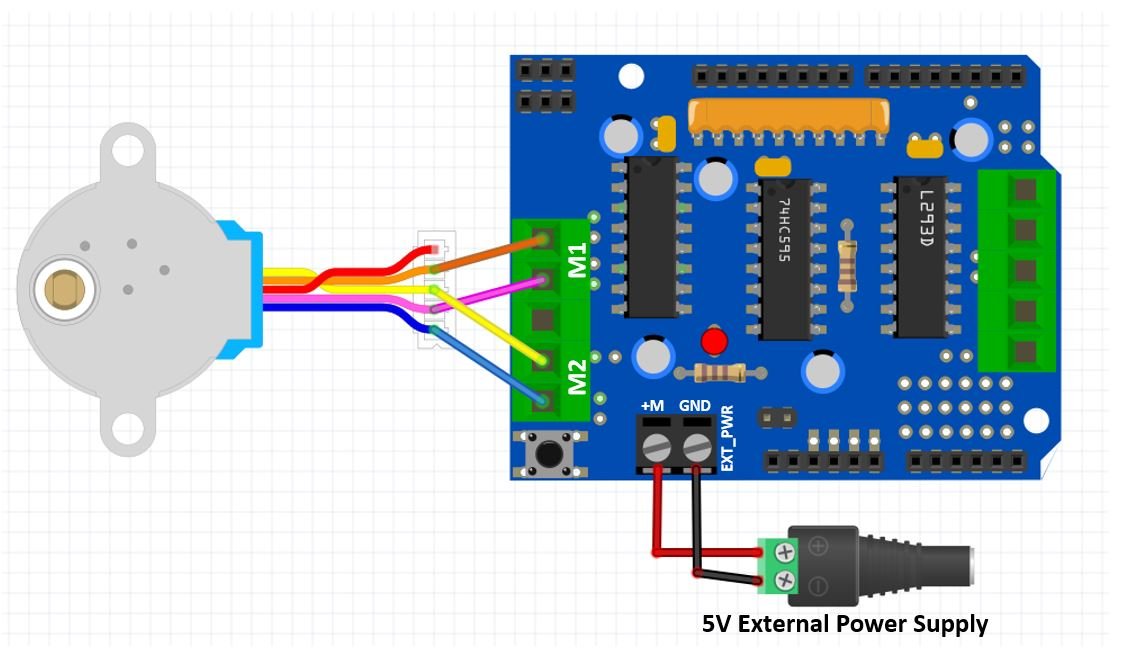
The first step is to mount the L293D motor driver shield on the Arduino board. Then we will connect a stepper motor with either M1, M2 or M3, M4 terminals. We have chosen to connect our stepper motor at M1,M2 terminals. Connect the stepper motor’s coloured wires with correct output pins of the shield. In our case, orange wire is coil1 and pink wire is coil2 hence they will connect with M1. Likewise, the yellow wire is coil3 and the blue wire is coil4 hence they will connect with M2 respectively.
28BYJ-48 is a uni-polar 5V stepper motor that takes electrical signals as input and rotates by converting these input signals into mechanical rotation. Connect positive terminal of power supply with +M terminal and negative terminal with GND terminal found at the EXT_PWR terminal block on the shield. Also the power jumper is removed from the shield.
For NEMA 17 stepper motor (bipolar)
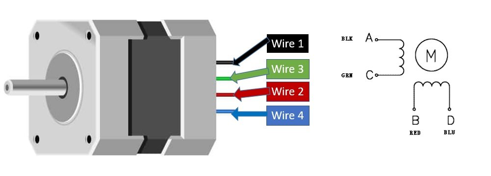
For which ever stepper motor you are using refer to its datasheet to find the correct coloured wires to differentiate the coil1, coil2, coil3 and coil4 wires. This will enable us to properly connect the motor with the output terminals of the shield.
This is the NEMA 17 stepper motor wire colours we are using in this project:
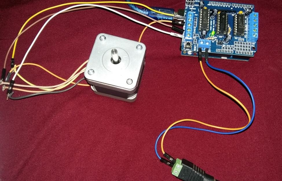
Assemble the circuit as shown in the connection diagram below.
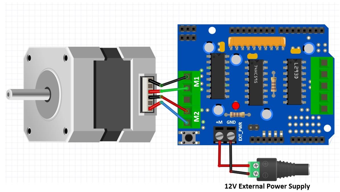
The first step is to mount the L293D motor driver shield on the Arduino board. Then we will connect a stepper motor with either M1, M2 (port 1) or M3, M4 (port 2) terminals. We have chosen to connect our stepper motor at M1,M2 terminals. Connect the stepper motor’s coloured wires with correct output pins of the shield. In our case, black wire is coil1 and green wire is coil2 hence they will connect with M1. Likewise, the red wire is coil3 and the blue wire is coil4 hence they will connect with M2.
NEMA 17 is a bipolar stepper motor rated at 12V. Connect positive terminal of power supply with +M terminal and negative terminal with GND terminal found at the EXT_PWR terminal block on the shield. Also the power jumper is removed from the shield.
Arduino Sketch Controlling Stepper Motor
Open your Arduino IDE and go to File > New. A new file will open. Copy the code given below in that file and save it.
This basic sketch will show us how to control a stepper motor’s speed and direction of rotation using the L293D motor driver shield with the AFMotor.h library.
#include <AFMotor.h>

const int steps_per_rev = 200; //Set to 200 for NIMA 17 and set to 48 for 28BYJ-48

// Motor connected with port1 (M1 and M2)
AF_Stepper motor(steps_per_rev, 1);

void setup() {
  Serial.begin(115200);
  motor.setSpeed(50);
}

void loop() {
  Serial.println("Single coil");
  motor.step(400, FORWARD, SINGLE);
  motor.step(100, BACKWARD, SINGLE);

  Serial.println("Double coil");
  motor.step(400, FORWARD, DOUBLE);
  motor.step(400, BACKWARD, DOUBLE);

  Serial.println("Interleave");
  motor.step(400, FORWARD, INTERLEAVE);
  motor.step(400, BACKWARD, INTERLEAVE);

  Serial.println("Micrsostep");
  motor.step(400, FORWARD, MICROSTEP);
  motor.step(400, BACKWARD, MICROSTEP);
}
How the Code Works?
Firstly, we will include the AFMotor.h library. This library provides useful functions that make it easy to control the motors using Arduino.
#include <AFMotor.h>The next step is to define the steps per revolution. This is the number of steps our motor requires to move one complete revolution. If using NEMA 17 set the value to 200. If using 28BYJ-48 instead set the value to 48.
const int steps_per_rev = 200; //Set to 200 for NIMA 17 and set to 48 for 28BYJ-48Then we will create an object of the library called motor and specify the steps per revolution of the motor as the first parameter and the port number with which we have connected the stepper motor as the second parameter.
// Motor connected with port1 (M1 and M2)
AF_Stepper motor(steps_per_rev, 1);
Inside the setup() function, Serial.begin() is used to establish the serial connection between the development board at a baud rate of 115200. We will use the setSpeed() method on the motor instance and pass the speed of the motor in rpm as an argument inside it. In our case we are setting the stepper motor speed to 50 revolutions per minute.
void setup() {
  Serial.begin(115200);
  motor.setSpeed(50);
}
Inside the loop() function we will move the stepper motor in both the forward and backward directions with different step types. The step() method takes in three parameters. The first parameter is the number of steps. The second parameter is the direction of rotation FORWARD/BACKWARD. The third parameter is the step type. The step type can take in the following values:
- SINGLE: In this case a single coil will be powered on at one time.
- DOUBLE: two coils will be powered on at one time.
- INTERLEAVE: Half step is created by switching from single to double. The speed will get reduced.
- MICROSTEP: Mircosteps are created in each full step.
void loop() {
  Serial.println("Single coil");
  motor.step(400, FORWARD, SINGLE);
  motor.step(400, BACKWARD, SINGLE);

  Serial.println("Double coil");
  motor.step(400, FORWARD, DOUBLE);
  motor.step(400, BACKWARD, DOUBLE);

  Serial.println("Interleave");
  motor.step(400, FORWARD, INTERLEAVE);
  motor.step(400, BACKWARD, INTERLEAVE);

  Serial.println("Micrsostep");
  motor.step(400, FORWARD, MICROSTEP);
  motor.step(400, BACKWARD, MICROSTEP);
}
Demonstration
To see the demonstration of the above code, upload the code to Arduino. Before uploading the code, make sure to select Arduino UNO from Tools > Board.
Also, select the correct COM port to which the Arduino board is connected from Tools > Port.
Once the code is uploaded to your board, the motor will start rotating.
Watch the video demonstration below:
Controlling Servo Motors with L293D Motor Driver Shield with Arduino
We will require the following equipment.
Required Equipment:
- Arduino
- L283D Motor driver shield
- Servo Motor
- Connecting Wires
Assemble the circuit as shown in the connection diagram below.
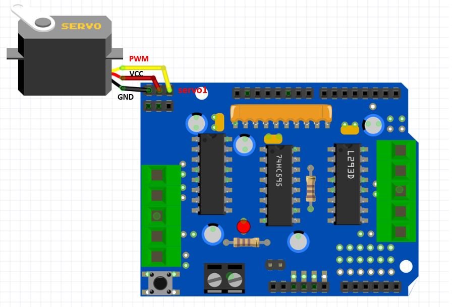
The first step is to mount the L293D motor driver shield on the Arduino board. Then we will connect a servo motor with one of the three pin headers found at the top left of the shield.
We will use SG90 servo motor for this project. SG90 is a low cost and high output power servo motor. It can rotate up to 180 degrees and each step can be of maximum 90 degrees.
It consists of three pins only: PWM, ground and VCC pin. If connecting the servo motor with the first header pins, the PWM pin of the servo motor will get connected with PWM pin10 of Arduino board. Likewise if connecting the motor with the second header pins, the PWM pin of the servo motor will get connected with the PWM pin9 of the Arduino board.
Additionally, we will not require an external power source to power the motor as the 5V from Arduino will be adequate to power the motor. In this case, make sure the power jumper is present on the shield.

Arduino Sketch Controlling Servo Motor
Open your Arduino IDE and go to File > New. A new file will open. Copy the code given below in that file and save it.
This basic sketch will show us how to control a stepper motor’s speed and direction of rotation using the L293D motor driver shield with the Servo.h library.
#include <Servo.h>

Servo servo;
int Position = 0;

void setup()
{
  servo.attach(10);
}

void loop()
{
  // rotates from 0 degrees to 180 degrees
  for(Position = 0; Position <= 180; Position += 1)
  {
    servo.write(Position);
    delay(15);
  }
  // rotates from 180 degrees to 0 degrees
  for(Position = 180; Position>=0; Position-=1)
  {
    servo.write(Position);
    delay(15);
  }
}
How the Code Works?
Firstly we will include the built-in Servo.h library.
#include <Servo.h> Then we will create an object of this library called ‘servo.’
Servo servo; The ‘Position’ variable holds the current position of the servo motor’s arm. Initially we have set it to 0.
int Position = 0; Inside the setup() function, we will attach digital pin10 with the servo object. Notice this is the GPIO pin that is connected with the PWM pin of the servo motor.
void setup()
{
  servo.attach(10);
}
Inside the loop() function, we will move the servo motor’s arm clockwise and anti-clockwise using the write() method on the servo object. Here we are passing the ‘Position’ variable as a parameter inside this function. This will position the servo arm according to the values held in the Position variable that will first vary from 0-180 degrees and then 180 to 0 degrees by using a for loop.
void loop()
{
  // rotates from 0 degrees to 180 degrees
  for(Position = 0; Position <= 180; Position += 1)
  {
    servo.write(Position);
    delay(15);
  }
  // rotates from 180 degrees to 0 degrees
  for(Position = 180; Position>=0; Position-=1)
  {
    servo.write(Position);
    delay(15);
  }
}
Demonstration
To see the demonstration of the above code, upload the code to Arduino. Before uploading the code, make sure to select Arduino UNO from Tools > Board.
Also, select the correct COM port to which the Arduino board is connected from Tools > Port.
Once the code is uploaded to your board, the motor will start rotating.
Watch the video demonstration below:
You may like to read our other articles on L293D IC:
- Stepper Motor Control with L293D Motor Driver IC and Arduino
- DC Motor Speed and Direction Control with L293D Driver IC and Arduino
- L293D Motor Driver IC introduction, pinouts and how to use
- WIFI CONTROLLED ROBOT USING ARDUINO and BLYNK
- Voice Controlled Robot using Arduino and voice recognition app
- how to make obstacle avoidance robot using arduino
You may also like to read other motor driver tutorials: