There are multiple kinds of motion we face in our daily life some are linear some are rotatory motion. Both motions have their importance in machines and our life. In the 19th century, the scientist started discovering/inventing some ways of producing current and motions when British physicist John Ambrose Fleming invented the right-hand rule.
Why do we need motors?
The right-hand rule was invented in the 19th century and it shows that we can produce current by combining the magnetic field and motion by following some specific rules. It also shows that we can produce the magnetic field and motion by combining one of each with the current.
After the invention of right-hand rule, a DC motor was invented by British scientist William Sturgeon. The DC motor was the first motor used by the scientist to convert the electric current to rotatory motion. DC Motor in the late 19th century has its own use but after the discovery of AC motor by Nikola Tesla and a wide amount of usage of AC current in industry and houses. The usage of AC motor became very much popular in the 20th century. But after the invention of the ICs DC motor again start gaining its popularity.
Why we need a Motor Driver?
Every AC and DC motor have the ability to rotate in both directions. AC motor has its own rules and usage, but DC motor could rotate in another direction just by changing the polarity of the current. Now a day mostly DC Motors are used to produce rotatory motion due to its high efficiency. But in some cases, we need to rotate the motor in both directions. Like robots, cars, etc. There are multiple circuits by which motor could be rotated in both directions just by using some diodes and transistors. But those circuits are complex to make. To avoid the complexity and IC name l293d was invented by which not only direction, other multiple functions could be achieved just by the blink of an eye.
- Another motor driver IC L298N
L293D Motor Driver Introduction
L293d IC is known as a motor driver. It is a low voltage operating device like other ICs. The other ICs could have the same functions like L293d but they cannot provide the high voltage to the motor. L293d provides the continuous bidirectional Direct Current to the Motor. The Polarity of current can change at any time without affecting the whole IC or any other device in the circuit. L293d has an internal H-bridge installed for two motors.
H-Bridge is an electrical circuit that enables the load in a bidirectional way. L293d bridge is controlled by external low voltage signals. It may be small in size, but its power output capacity is higher than our expectation. It could control any DC motor speed and direction with a voltage range of 4.5 – 36 Volts. Its diodes also save the controlling device and IC from back EMF. To control the max 600mA amount of current an internal “Darlington transistor sink” installed in it, which could be used to control a large amount of current by providing a small amount of current. It has also internal “pseudo-Darlington source” which amplifies the input signal to control the high voltage DC motor without any interception.
L293D pinout

L293D Pin Configuration Details
| Pin1 (Enable) | Pin 1 is known as the enable pin. It has a major effect on Input and output. If there is High logical signal on enable pin (EN) then there will be input and output between pin 2,3,6 & 7 (Input 1, Output 1, Input 2 & Output 2) |
| Pin2 (Input 1) | Mostly input means where we provide the input to give the output. But here Input 1 means which polarity we want to give at Output 1. |
| Pin3 (Output 1) | Output 1 is the input of the first motor/Motor 1. It attaches to its one end. |
| Pin4 (Ground) | The ground pin will attach to the ground of the circuit. |
| Pin5 (Ground) | The ground pin will be attached to the ground, and it will remain common with the previous ground. |
| Pin6 (Output 2) | Output 2 will attach to the input of the first motor/Motor 1. It will attach to its second end. |
| Pin7 (Input 2) | Input 2 will attach to the control button or device to control the Output 2 just like Input 1. |
| Pin8 (Vcc) | Pin8 is the voltage pin for Motor. It will device how much power we are going to attach the Motor. This Power should not be more than 36 volts and should not be less than 4.5 volts. |
| Pin9 (Enable) | Pin 9 is also the same as Pin 1. It controls the input and output signals. Pin 9 Controls the connection between Input 3, Input 4, Output 3 and Output 4. It also enables the connection when the logic signal will be High (1). |
| Pin10 (Input 3) | Input 3 will control the output polarity of the Pin 11 (Output 3) by logic signals. |
| Pin11 (Output 3) | Output 3 will be connected to the one end of the second motor. |
| Pin 12 (Ground) | Pin 12 will attach to the common ground with all other grounds. |
| Pin13 (Ground) | Pin 13 will also be attached to the common ground with all other grounds. |
| Pin14 (Output 4) | Pin 14 will attach to the second end of the second motor. |
| Pin15 (Input 4) | Pin 15 will control the output polarity of the Pin 14 (Output 4) by logic signals. |
| Pin16 (Vcc) | Pin 16 will the Power we will provide to the L293D to activate it or to turn it on. The power level of Pin 16 should be 4.5 – 7Volts. Voltage more than 7 will burn the IC |
FEATURES
- L293d could be used to control the two motors at the same time.
- It has the ability to control the speed by using the enable pin.
- The direction is also easy to change.
- Voltage supply range is higher than other IC. Voltage range between 4.5-36 volts can easily handle by the IC to the motor.
- The motor has a maximum continuous range of current close to 600mA but the maximum peak current range is 1.2A
- It has an automatic shutdown system on thermal condition.
- Its working range is from 0 – 70 degree which is much higher for any small-sized IC.
- It has an internal back emp protection for IC and the controlling device.
How to Use L293D?

L293d may have an internal complex circuit, but it is easy to use in real life. Just attach two motors with output pins. Remember at output 1 and output 2 same motor should be connected and it needs to be the same for output 3 and output 4. All ground should be common with both the power supplies provided to the IC. The enable pins are used to control the outputs but when we use the microcontrollers or microprocessor these enable pins can be used to control the speed of the motor.
Motor Control Pins
The Input pins have a major role to control the direction of the motor. If Input 1 (Pin 2) is High and Enable (Pin 1) is high low but Input 2 (Pin 7) is low than motor will rotate clockwise at motor attached to the Pin 3 & 6. The rotation will be anti-clockwise when Input 2 (Pin 7) & Enable (Pin 1) is high but Input 1 (Pin 2) is low. To control the rotation of Pin 11 & 14 the Pin 9,10 & 11 will be used. If Input 1 & Input 2 has the same logic at the same time or enable 1 pin is low then there will be no rotation. This will be the same for Input 3, Input 4 and enable 2.
L293D Example Circuits
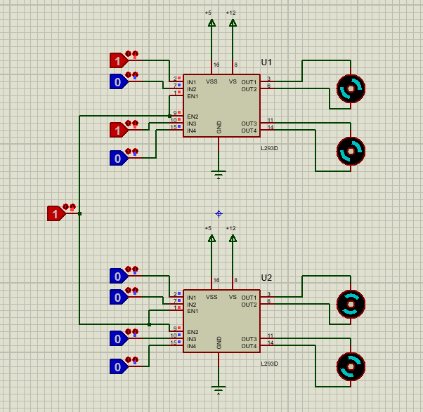
As you read above L293d has multiple featured and usage where it can be used without any limitations. Here is an example of the circuit of street racing cars. We just need to use two L293d to control the car.
- Connect all the enable pins together and use the single button to control the motor power state.
- Then attach the input pins with any microcontroller or microprocessor and control their direction.
- The speed of the car could be control by proving the controllable PWM on enable pins.
- After attaching all pins to the microcontroller/microprocessor follow these states to control the direction of the car.
Moving Robot Forward or Backward
If Input 1 and Input 3 of both L392d is high then the car will move in forwarding direction. To change the direction from forward to backwards just change all inputs of forwarding direction from high to low and low to high.

Moving Robot Left or Right
- To move the turn to the right of left you just need to turn off all the wheel of that direction where they should be turned.
- If you want the car to take the left turn than just turn off the right tyros by giving them the same inputs to the right wheel. Do the same for the left wheel to move left.

These all above methods are usually used for the car. These functions could be developed on the bases of the requirement. In robot or any other car different methods will be used but to control multiple DC motors (range 4.5 -36 Volts) direction and speed L293D is the best option.
Proteus Simulation
You may also like to have a look at practical examples with L293D:
- WiFi controlled robot using Arduino
- GSM based control of dc motor
- Control 2 DC motors via Bluetooth and Arduino
- Voice-controlled robot
APPLICATIONS of L293D
- It could be used to control stepper and DC motor direction and Speed.
- Due to a separate power supply for the motor, it could be used in small children’s cars, street racing cars, or robots.
- It could be used for latching relay drivers.
I like this site.
me too