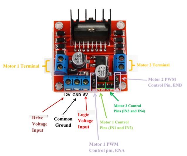
L298N motor driver IC has many applications in the embedded field, especially on the robotics side. Most of the microcontrollers operate on very low voltage (5v) and current while the motors require higher voltages and current So, the microcontrollers cannot provide them such higher current. For this purpose, we use motor driver ICs.
The motor driver is a little current amplifier. It takes a low current signal and gives out a high current signal which can drive a motor. It can also control the direction of the motor. Motor drives are of many kinds depending upon the maximum supply voltage, maximum output current, rated power dissipation, load voltage, and number outputs, etc. Here we are going to discuss motor driver L298N. It is used in dc motor speed control project and you can interface dc motor easy with microcontroller using this motor driver. and also in Bluetooth controlled robot using a pic microcontroller. you can check the line follower robot for more about its applications.
Features of the L298N motor driver Module
L298N is an integrated circuit multi watt 15 package and capable of giving high voltage. It is a high current dual full-bridge driver that is designed to accept standard TTL logic levels. It can drive inductive loads e.g relays, solenoids, motors (DC and stepping motor), etc.
Its basic features are:
- Maximum supply voltage 46V
- Maximum output DC current 4A
- Low saturation voltage
- Over-temperature protection
- Logical “0” Input Voltage up to 1.5 V
PIN DIAGRAM of L298N
The pin diagram in top view for L298N is given below: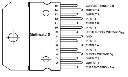
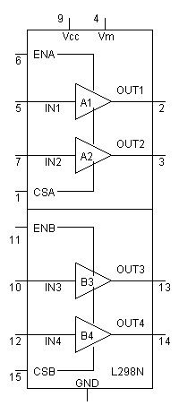
Motor Driver Internal Circuit
PIN DESCRIPTION of L298N module

L298N consists of four independent power amplifiers. Two of them form H-bridge A while other two form H-bridge B. One H bridge is used to switch the polarity in controlling direction of DC motor. Pair of H Bridge is used to control a bi-polar stepper motor.
- Amp A1 and A2 => H Bridge A
- Amp B1 and B2 => H Bridge B
Basically L298N is used to drive inductive or magnetic loads, so there can come voltage spikes in output. To avoid that voltage spikes there should be some internal parasitic or Flywheel diodes. But it lacks them. We use externally these flywheel diodes. They can be 1N5819 schottky diodes or 1N4001 rectifier diodes.
Each bridge is provided with enable pins (ENA, ENB) and current sense pins (CSA, CSB). Current sense pins can be tied to ground but we can also insert low value resistor and its voltage reading is proportional to current. Both enable pins can be used at the same time which makes all for outputs active at the same time.All the four inputs and Enable pins work on 5v TTL logic which makes the connection easy with microcontrollers.
- ENA=5v, High logic (Amplifier A1 and A2 on)
- ENA=0v, Low logic (Amplifier A1 and A2 off)
- ENB=5v, High logic (Amplifier B1 and B2 on)
- ENB=0v, Low logic (Amplifier B1 and B2 off)
L298N motor driver module working
- Now consider an example. We will use H bridge motor diver IC L298N and two DCmotors. This IC is used to control these motors. What we want to do is to change the polarity of motors so they can run in either direction depending upon logic.
- INPUTS: Four inputs are provided to the four power amplifiers of L298N. We can use push buttons and whenever specific push button is pressed, specific motor will start running. Two inputs will monitor each motor. Instead of push button, we can use logic toggle in proteus simulation for our ease.
- Enable bits are used to select specific amplifier. ENA can select two amplifiers A1, A2 and similarly ENB can select two amplifiers B1, B2. While using as a bridge circuit, ENA selects bridge A and ENB selects bridge B. To drive both the motors by using H bridges, both enable bits are set high.
- OUTPUTS: There are four outputs. The output for motor A is obtained from out1 out2 pins and similarly for motor Boutput is obtained from out3 out4 pins. L298N does not have built in protection diodes we usedexternal diodes to prevent the IC from getting damaged.
- This IC is using two different voltages. On input side, 5v is given to the pin 9 (Vss), push buttons and enable bits.On output side,pin 4 (Vs) supplies the motors and it can be upto 46 volts.Here we are not using the current sensing scheme, so we have grounded those pins 1 & 15. Motors speed will be lower if low voltages are on output side.
Example of L298N module to control motor direction
Enabling pin 6, if we give logic as:
| Pin5=high, pin7 = low, motor A will start turning clockwise. Pin5=low, pin7 = high, motor A will start turning anticlockwise Pin5=high, pin7 = high, motor A will stop Pin5=low, pin7 = low, motor A will stop |
Enabling pin 11, if we give logic as:
| Pin10=high, pin12 = low, motor B will start turning clockwise Pin10=low, pin12 = high, motor B will start turning anticlockwise Pin10=high, pin12 = high, motor B will stop Pin10=low, pin12 = low, motor B will stop |
In this example of proteus, we used toggle inputs. We can also change the toggle input settings in start if we have to run the motor continuously.In using push buttons, on side of buttons is attached with power supply and others are attached with inputs of L298N. As long as the button is pressed, the motor will keep running in specified direction according to the logic given through the button. Also use the heat sinks when doing practically.
Video lecture on dc motor driver
Circuit diagram to control 2 motors with L298N
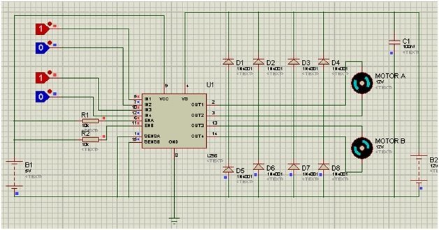
Here we have simulated the above example. At the present state, both motors are running in a clockwise direction. If I invert both the logics, they will run in an anti-clockwise direction. And if same logic is given to any motor’s input, it will not be able to move in either direction and will stop.
thanks alot what you giving the circuit and for your explanations
so,furtherly if you have a code for pic 18 micro controller pls try to send now
Thanks a lot for this, it helps me a lot in my project ! continue like this
I wanna know pic16f887 interface with L298n motor driver and bluetooth module hc-06 and dc motor.please reply me.
Yar line follow robot ki circuit diagram Tiva use ho his ma mil Sakti hai kia