In this tutorial, we will learn how to interface a DC motor with the ATmega32 microcontroller using the L293D motor driver IC. The L293D IC is a powerful motor driver IC. It features a dual-channel H-bridge motor driver, making it easy to drive two motors. We will discuss in detail about this motor driver IC and explore how to interface it with an AVR microcontroller. Additionally, we will provide you with a code that can control the speed and direction of the DC motors easily. Let’s get started.
Recommended Components
The following parts and reference books are useful for building and learning AVR microcontroller projects.
| Component | How it’s used in your AVR projects | Buy on Amazon |
|---|---|---|
| ATmega32 (AVR) microcontroller | The 8-bit AVR MCU used across these tutorials (LED, LCD, motors, timers, etc.). | Check Price |
| USBasp programmer (ISP) | Burns the compiled HEX file into the AVR over the ISP header. | Check Price |
| Breadboard | Solderless base for wiring the AVR and the project’s components. | Check Price |
| Jumper Wires | Make the connections between the MCU, components and power rails. | Check Price |
| Book: The AVR Microcontroller & Embedded Systems (Mazidi & Naimi) | AVR programming in Assembly & C — timers, USART, ADC, SPI, I2C and PWM. | Check Price |
| Book: AVR Programming (Elliot Williams, Make:) | A hands-on, project-based guide to bare-metal AVR programming. | Check Price |
As an Amazon Associate we earn from qualifying purchases. Prices and availability are accurate as of the date/time indicated and are subject to change.
DC Motors Introduction
DC motors are electro-mechanical machines which convert electrical energy into mechanical (rotational) energy. If you are looking to develop a robot such as a line follower robot, or obstacle avoidance robot, these DC motors will be the first choice for you. They are available in direct drive or geared types. But, both types require a dc voltage to operate. Therefore, we apply a DC voltage to drive DC motors.
DC Motor Speed Control
The speed of rotation of motors is directly related to the input voltage. The higher the input voltage, the higher will be the rotational speed of the motor. But the voltage should be within the operating voltage range.
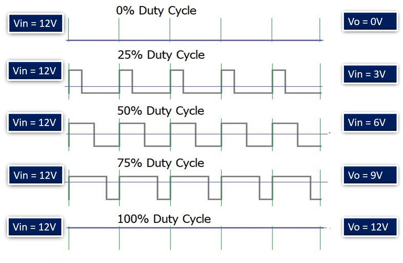
One important point to note here is that if we want to control the speed of a DC motor, we will need to provide a variable voltage to the DC motor. For example, If the operating voltage range of a motor is between 3 – 6 volts. If we apply 3 volts input, the motor will run at its lowest rated speed. Similarly, if we apply 6 volts, the DC motor will run at its highest-rated speed. In short, we can control the speed of rotation by giving a variable input voltage to a DC motor. Usually, a pulse width modulation technique is used to generate a variable dc voltage from a constant dc voltage source.
DC Motor Direction Control
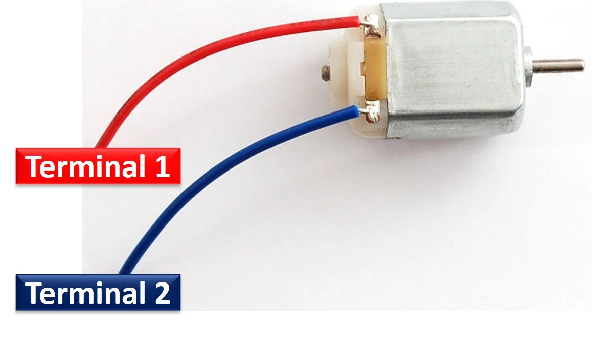
As you know, in the case of a DC power supply, there is a concept of polarity, with positive and negative terminals of a battery. The polarity of the input voltage source determines the direction of rotation of a DC motor. For instance, if we connect the positive terminal of the battery to one terminal and the negative terminal of the battery to another terminal of the DC motor, it will start rotating in a clockwise direction. However, if we interchange the connection of the battery by connecting the opposite polarity, the DC motor will start rotating in the opposite direction, as shown in the simulation below.
Generally, an H-Bridge circuit is used to provide opposite polarity power to a DC motor without changing the actual power supply connections. An H-Bridge consists of four switches, resistors, and two control signals, as shown in the figure. Two logic probes control the direction of a DC motor. When the left probe logic signal is on, the motor rotates in an anti-clockwise direction, and when the right probe logic signal is on, the motor rotates in a clockwise direction.

L293D Motor Driver IC
L293D IC is known as a motor driver. It is a low-voltage operating device like other ICs. L293D provides continuous bidirectional direct current to the motor. The polarity of the current can change at any time without affecting the whole IC or any other device in the circuit. L293D has an internal H-bridge installed for two motors.
An H-bridge is an electrical circuit that enables the load to be controlled in a bidirectional way. L293D bridge is controlled by external low-voltage signals. It may be small in size, but its power output capacity is higher than our expectations. It can control the speed and direction of any DC motor with a voltage range of 4.5 – 36 Volts. Its diodes also protect the controlling device and IC from back EMF. To control a maximum of 600mA current, an internal “Darlington transistor sink” is installed in it, which can be used to control a large amount of current by providing a small amount of current. It also has an internal “pseudo-Darlington source” which amplifies the input signal to control the high voltage DC motor without any interference.
Pinout
The diagram below shows the pin out of L293D IC:

Enable Pins
- Pin1 (Enable): Pin 1 is known as the enable pin. It has a major effect on Input and output. If there is a high logical signal on enable pin (EN) then there will be input and output between pins 2,3,6 & 7 (Input 1, Output 1, Input 2 & Output 2)
- Pin9 (Enable): Pin 9 is also the same as Pin 1. It controls the input and output signals. Pin 9 Controls the connection between Input 3, Input 4, Output 3, and Output 4. It also enables the connection when the logic signal will be High (1).
Input Pins
- Pin2 (Input 1): Mostly input means where we provide the input to give the output. But here Input 1 means which polarity we want to give at Output 1.
- Pin7 (Input 2): Input 2 will attach to the control button or device to control Output 2 just like Input 1.
- Pin10 (Input 3): Input 3 will control the output polarity of Pin 11 (Output 3) by logic signals.
- Pin15 (Input 4): Pin 15 will control the output polarity of Pin 14 (Output 4) by logic signals.
Output Pins
- Pin3 (Output 1): Output 1 is the input of the first motor/Motor 1. It attaches to one end.
- Pin6 (Output 2): Output 2 will attach to the input of the first motor/Motor 1. It will attach to its second end.
- Pin11 (Output 3): Output 3 will be connected to one end of the second motor.
- Pin14 (Output 4): Pin 14 will attach to the second end of the second motor.
Power Pins
- Pin8 (Vcc): Pin8 is the voltage pin for Motor. It will decide how much power we are going to attach the Motor. This Power should not be more than 36 volts and should not be less than 4.5 volts.
- Pin16 (Vcc): Pin 16 will the Power we will provide to the L293D to activate it or to turn it on. The power level of Pin 16 should be 4.5 – 7 Volts. Voltage more than 7 will burn the IC
- Pin4 (Ground) and Pin5 (Ground): The ground pins will attach to the ground of the circuit.
- Pin12 (Ground) and Pin13 (Ground): These will attach to the common ground with all other grounds.
Control Pins
The L293D IC features both speed and direction control pins to control two motors simultaneously.
Direction Control Input Pins
The direction control pins are the four input pins (Pin2 IN1, Pin7 IN2, Pin10 IN3, Pin15 IN4) on the IC.
Through these input pins we can determine whether to move the dc motor forward or backwards. IN1 and IN2 control motor A’s spinning direction whereas IN3 and IN4 control motor B’s spinning direction. The table below shows the logic signals required for the appropriate spinning action for motor A.
| IN1 | IN2 | Motor Action |
|---|---|---|
| 1 (HIGH) | 1 | OFF |
| 1 | 0 (LOW) | Backward |
| 0 | 1 | Forward |
| 0 | 0 | OFF |
As seen from the table, whenever one of the inputs is in a HIGH state (5V) then the motor will spin. Otherwise, when both the inputs are LOW (ground) state or both are in HIGH state then the motor stops. In order for motor A to spin forward, IN1 should be LOW and IN2 should be HIGH. For backwards motion, IN1 should be HIGH and IN2 should be LOW. Motor B is also controlled in a similar way.
Speed Control Pins
The speed control pins pin1 (EN1,2 or ENA) and pin 9 (EN3,4 or ENB) on the IC, control the speed of the dc motor and turn it ON and OFF.
EN1,2 controls the speed of one motor and EN3,4 controls the speed of the other motor. If both of the pins are in a logic HIGH (5V) state, then both the motors are ON and spinning at maximum speed. If both of the pins are in a logic LOW (ground) state, then both the motors are OFF. Through the PWM functionality, we can also control the speed of the motor.
You can know more about the L293D motor drivers here:
Features
- L293D could be used to control the two motors at the same time.
- It has the ability to control the speed by using the enable pin.
- The direction is also easy to change.
- Voltage supply range is higher than other IC. Voltage range between 4.5-36 volts can easily handle by the IC to the motor.
- The motor has a maximum continuous range of current close to 600mA but the maximum peak current range is 1.2A
- It has an automatic shutdown system on thermal condition.
- Its working range is from 0 – 70 degree which is much higher for any small-sized IC.
- It has internal back emp protection for IC and the controlling device.
DC Motor Interfacing with Atmega32 Circuit Diagram
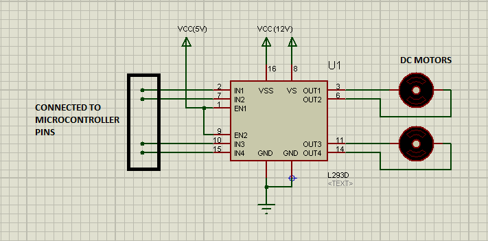
The circuit on proteus is shown in the figure given below:
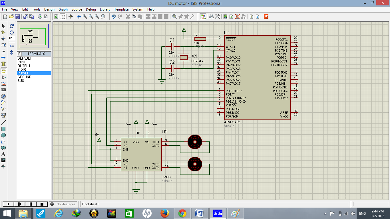
To make the circuit on proteus, select Atmega32, L293 IC, crystal, DC motor, and rest of the components from the built-in library.
- Connect the IN1, IN2, IN3 & IN4 pins of L293 with PB0, PB1, PB2 & PB3 pins of Atmega32.
- Pin EN1 & EN2 pins of L293 are connected to 5V
- Connect the VCC with 12V and GND pins of L293 with the ground.
- Set the frequency of crystal and Atmega32 to 16MHz.
The following truth table will help you develop an understanding of the basic movements of motors for building a code.
| MOTOR A | MOTOR B | DESCRIPTION |
| 0 | 0 | Both Motors stop |
| 0 | 1 | Motors move in a clockwise direction |
| 1 | 0 | Motors move in clockwise direction |
| 1 | 1 | Both Motors stop |
Code
We use Atmel Studio 6 for coding and the code is written in C language.
#ifndef F_CPU
#define F_CPU 16000000UL // 16 MHz clock speed
#endif

#include <avr/io.h>         //standard AVR library
#include <util/delay.h>     // delay library

int main(void) //main starts
{

   DDRB= 0xFF; // direction of port B as output

  while(1)   //infinite loop
{

PORTB = 0x05; // motor rotation in clockwise direction
_delay_ms(3000);    //delay of 3 sec
PORTB = 0x00;// motor stopped
_delay_ms(1000);    //delay of 1 sec

PORTB = 0x0A; //motor rotation in anticlockwise direction
_delay_ms(3000);    //delay of 3 sec
PORTB = 0x00;// motor stopped
_delay_ms(1000);    //delay of 1 sec

}     //while loop end

}      //main end
As the motors are connected to the first four pins of PORTB, we make the direction of PORTB as output by using the register (DDRB). The comments are shown after “//”. The first motor will rotate in a clockwise direction by setting PB.0 & PB.2 high for 3 seconds, and then both motors stop for one second by setting all four pins to low. For the anticlockwise direction, set PB.3 & PB.1 high. The code will execute infinitely due to the while loop.

Demonstration
To observe the functionality of the circuit according to the given code, upload the HEX file of the code into the circuit and observe the simulation results.

Applications
There are several applications of DC motors. They can be used in different robots with wheels and robotic cars to move in various directions. Especially for line-following robots (LFR), the use of DC motors is very common.
Thanku so much..Great job
HI , could you help me with the same project but with different in put with switch ..