Line follower robot using avr microcontroller. In this tutorial you will learn how to design a line follower robot using avr microcontroller and path sensors. It follow a black line automatically and it also turn it direction according to black line. Liner follower robot is very famous project at university level among electrical, electronics, computer and software engineering students. There are a lot of competitions held every year in engineering universities related to robotics. But for first year engineering students, Liner follower robot is very popular.Because it is easy to make and can be easily ready to run with in minimum time. you can may also like to check out other robotics projects:
- Obstacle avoidance robot
- Voice controlled robot
- Metal detector robot
- wifi controlled robot using Arduino
- Pick and place robotic arm
Recommended Components
The following parts and reference books are useful for building and learning AVR microcontroller projects.
| Component | How it’s used in your AVR projects | Buy on Amazon |
|---|---|---|
| ATmega32 (AVR) microcontroller | The 8-bit AVR MCU used across these tutorials (LED, LCD, motors, timers, etc.). | Check Price |
| USBasp programmer (ISP) | Burns the compiled HEX file into the AVR over the ISP header. | Check Price |
| Breadboard | Solderless base for wiring the AVR and the project’s components. | Check Price |
| Jumper Wires | Make the connections between the MCU, components and power rails. | Check Price |
| Book: The AVR Microcontroller & Embedded Systems (Mazidi & Naimi) | AVR programming in Assembly & C — timers, USART, ADC, SPI, I2C and PWM. | Check Price |
| Book: AVR Programming (Elliot Williams, Make:) | A hands-on, project-based guide to bare-metal AVR programming. | Check Price |
As an Amazon Associate we earn from qualifying purchases. Prices and availability are accurate as of the date/time indicated and are subject to change.
Applications of line follower robot
Line follower robot which is usually make at university level is just to make students familiar with the field of robotic. But actual robots use in fields are much more complex and they can perform very complicated task in industry. It is not possible to make a practical robot at university level. That’s why international robotics club encourage students to make simple robots like Liner follower robot, obstacle avoided robot, metal detection robot to get basic understanding of practical robots.In this article I have presented you an idea of Liner follower robot. How to make line follower robot using microcontroller.
Circuit working of line follower robot
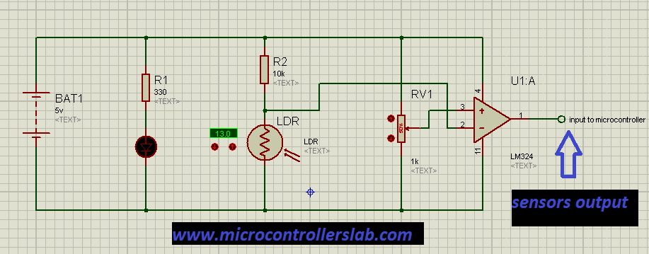
Block diagram of line follower using avr microcontroller is shown below. As I have clearly mentioned in block diagram. Two motors are used. One motor is attached with left Tyre of robot and another motor is attached with right Tyre of robot. Front wheel of Line follower robot is freely moving wheel. Motor driver IC is used to rotate both motors either clock wise or anti clock wise direction according to turning direction of Line follower robot. L298 motor driver IC is used as a motor driver IC. Microcontroller Atmega16 is used to give control signals to motor driver IC according to sensors output. Light dependent resistor in combination with light emitting diode is used to sense black line. In case robot goes off from black line, respective sensor operate and microcontroller sense its value and take control control actions by turn motors either clock wise or anti clock wise. Block diagram of line follower robot is shown below :
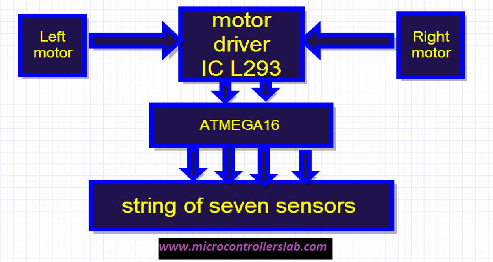
Sensors circuit diagram for line follower robot
Circuit diagram of line follower robot using avr microcontroller

Coding for line follower robot
// ***********************************************************
 // Project: LINE FOLLOWER ROBOT
 // Author: Bilal Malik     "microcontrollerslabhub@gmail.com"
 // Module description:
 // ***********************************************************
 #include <avr\io.h> // Most basic include files
 #include <avr\interrupt.h> // Add the necessary ones
 #include <util\Delay.h> // here
 #include <stdio.h>

#define RS 0
 #define RW 1
 #define EN 2
 #define LCD_PORT PORTC
 #define LCD_DIR DDRC

#define CLEAR_LCD 0x01
 #define LCD_HOME 0x02
 #define LCD_LINE_1 0x80
 #define LCD_LINE_2 0xC0
 #define LCD_R_SHIFT 0x1C
 #define LCD_L_SHIFT 0x18
 #define FWD 0x0A
 #define REV 0x05
 #define R 0x02
 #define L 0x08
 #define CW 0x09
 #define CCW 0x06
 #define STOP 0x00
 #define B 0xFF

#define RSPEED OCR1AL
 #define LSPEED OCR1BL

#define MAX 3
 #define HMAX 1

void move(unsigned char dir);
 void Lcd_Cmd(unsigned char cmd);
 void lcd_message(char line, char * ptr );
 void lcd_data(unsigned char data);
 void lcd_init(void);

unsigned char i , rdev , ldev , ip , delay , dir , power , dirl , history[MAX] , hcount = 0 , rotpow , val = 0;

unsigned char rep=0, prev=0;

void disp()
 {
 char mess[] = "LINE FOLLOWING ROBOT CREATED BY";
 char mess2[] = "BILAL MALIK";
 lcd_message(LCD_LINE_1, mess );

_delay_ms(1000);

for(int i=0;i<20;i++)
 {
 Lcd_Cmd(LCD_R_SHIFT);
 _delay_ms(100);
 }
 Lcd_Cmd(LCD_HOME);
 lcd_message(LCD_LINE_2, mess2);
 _delay_ms(1000);

}

int main(void)
 {

lcd_init();
 disp();

PORTA = 0x00;
 DDRA = 0x00;

PORTB = 0xFF;
 DDRB = 0xFF;

PORTC=0x00;
 DDRC=0xFF;

PORTD=0xff;
 DDRD=0xff;

TCCR0=0x00;
 TCNT0=0x00;
 OCR0=0x00;

TCCR1A=0xA1;
 TCCR1B=0x0A;
 TCNT1H=0x00;
 TCNT1L=0x00;

OCR1AH=0xFF;
 OCR1AL=0xFF;
 OCR1BH=0xFF;
 OCR1BL=0xFF;

ACSR=0x80;// adc disable
 move(STOP);
 _delay_ms(1000);
 while(1)
 {

if(PINA!=0)
 {

ldev=0;
 rdev=0;
 val = PINA;

if((val & 0x08)==8)
 {
 rdev=1;
 ldev=1;
 }
 if((val & 0x04)==4)
 rdev=2;

if((val & 0x10)==0x10)
 ldev=2;

if((val & 0x02)==2)
 rdev=3;

if((val & 0x20)==0x20)
 ldev=3;

if((val & 0x01)==1)
 rdev=4;

if((val & 0x40)==0x40)
 ldev=4;
 if(rdev>ldev)
 move(L);
 else if(rdev<ldev)
 move(R);
 else if(rdev==ldev)
 move(FWD);
 }
 else
 {
 for(i=0,dirl=0;i
 {
 if(history[i]==L)
 {
 dirl++;
 }
 }
 if(dirl>HMAX)
 {
 move(CCW);//,0,rotpow);

_delay_ms(1000); // TESTING & DEBUG
 }
 else
 {
 move(CW);//,0,rotpow);

_delay_ms(1000); // TESTING & DEBUG
 }

_delay_ms(1000); // TESTING & DEBUG

}

};
 }
 void move(unsigned char dir)//,unsigned char delay,unsigned char power)
 {
 PORTD=dir;

char ch[10];
 itoa(dir,ch,10);
 Lcd_Cmd(CLEAR_LCD);

if(dir == STOP)
 {
 lcd_message(LCD_LINE_1, "STOP");
 }
 else if(dir == FWD)
 {
 lcd_message(LCD_LINE_1, "FORWARD");
 }
 else if(dir == REV)
 {
 lcd_message(LCD_LINE_1, "REVERSE");
 }
 else if(dir == R)
 {
 lcd_message(LCD_LINE_1, "RIGHT");
 }
 else if(dir == L)
 {
 lcd_message(LCD_LINE_1, "LEFT");
 }
 else if(dir == CW)
 {
 lcd_message(LCD_LINE_1, "CW");
 }
 else if(dir == CCW)
 {
 lcd_message(LCD_LINE_1, "CCW");
 }

lcd_message(LCD_LINE_2, ch );
 if(dir==L||dir==R)
 {
 hcount=(hcount+1)%MAX;
 history[hcount]=dir;
 }
 LSPEED=50;
 RSPEED=50;
 _delay_ms(1000);

}


void Lcd_Cmd(unsigned char cmd)
 {

LCD_PORT &= ~((1<<rs)|(1<<rw)); rs="" low="" for="" command,="" rw="" <span="" class="hiddenSpellError" pre="for " data-mce-bogus="1">write
 LCD_PORT |= (1<<EN); // Set enable
 LCD_PORT &= 0x0F;
 LCD_PORT |= (cmd & 0xF0); // Send upper nibble
 LCD_PORT &= ~(1<<EN); // Enable low
 _delay_ms(1);
 LCD_PORT |= (1<<EN); // Set enable
 LCD_PORT &= 0x0F;
 LCD_PORT |= (cmd << 4); // Send lower nibble
 LCD_PORT &= ~(1<<EN); // Enable low
 _delay_ms(1);
 }

void lcd_data(unsigned char data)
 {

LCD_PORT |= (1<<RS); //RS high for data
 LCD_PORT &= ~(1<<rw); rw="" low="" for="" <span="" class="hiddenSpellError" pre="for " data-mce-bogus="1">write
 LCD_PORT |= (1<<EN); // Set enable
 LCD_PORT &= 0x0F;
 LCD_PORT |= (data & 0xF0); // Send upper nibble
 LCD_PORT &= ~(1<<EN); // Enable low
 _delay_ms(1);
 LCD_PORT |= (1<<EN); // Set enable
 LCD_PORT &= 0x0F;
 LCD_PORT |= (data << 4); // Send lower nibble
 LCD_PORT &= ~(1<<EN); // Enable low
 _delay_ms(1);
 }

void lcd_init(void)
 {
 LCD_DIR = 0xFF;
 _delay_ms(15);
 Lcd_Cmd(0x03);
 _delay_ms(5);
 Lcd_Cmd(0x03);
 _delay_ms(1);
 Lcd_Cmd(0x03);
 _delay_ms(1);
 Lcd_Cmd(0x02);
 _delay_ms(1); //as said in the book
 Lcd_Cmd(0x28); //Set interface length
 _delay_ms(1);
 Lcd_Cmd(0x08); // Turn off display
 _delay_ms(1);
 Lcd_Cmd(0x01); //Clear display
 _delay_ms(1);
 Lcd_Cmd(0x06); //Set cursor move direction
 _delay_ms(1);
 Lcd_Cmd(0x0F); //Enable display cursor
 _delay_ms(1);
 }
 void lcd_message(char line, char * ptr ) // 1st argument is the string pointer the other is line No.
 {

//Lcd_Cmd(CLEAR_LCD);
 Lcd_Cmd(line); //move cursor to line

while(ptr != '\0')
 lcd_data((ptr++));

}
kindly don’t forget to share it with your friends on social media. Because sharing is caring :To download circuit diagrams of this project click on following link :
Hi;
Would you please give an example how to interfacing real time clock RTC DS 1307 with PIC 18f4520
by using C18 compiler.
Thanks;
I will post a article on real time clock in coming weeks. keep visiting my blog or subscribe to blog to get update about post in your email inbox
Very Good(Y)
how do you connect the diodes to the circuit
Hi please i want to do a project of an object like a car or robot folling another robot at a specified distance using PIC, what type of sensor do i need and code for the project, thanks
hi please help to make pid lineflower robot
Plz bro give complete circuit diagram