Interface Micro SD Card Module with Raspberry Pi Pico
In this user guide, we will learn how to interface a micro SD card with Raspberry Pi Pico using the microSD card module. This module provides an SPI interface to connect an SD card module with any microcontroller that supports the SPI communication protocol. Using a micro SD card is very convenient for applications where we need to store files or any type of data persistently, even when the microcontroller is powered off.Additionally, we will learn how to handle files on the microSD card, including reading from and writing to a file. Storage data — including text, video, audio, CSV, HTML, JavaScript, and CSS files — can all be conveniently stored on a microSD card. It is one of the most reliable and practical ways to store data in devices such as mobile phones, laptops, and personal computers.By the end of this tutorial, you will be able to mount a microSD card as a filesystem in MicroPython, create and write to a text file, and read data back from it. This makes it straightforward to build data loggers, configuration file readers, web servers, and many other applications that benefit from non-volatile local storage.
Recommended Components
The following components are used in this project or are helpful for getting started with Raspberry Pi Pico development.
Component
How it’s used in this project
Buy on Amazon
Raspberry Pi Pico
The RP2040 microcontroller board used in this tutorial.
As an Amazon Associate we earn from qualifying purchases. Prices and availability are accurate as of the date/time indicated and are subject to change.
Prerequisites
Before we start this lesson, make sure you are familiar with and have the latest version of Python 3 installed on your system and have set up MicroPython on your Raspberry Pi Pico. Additionally, you should have a working Integrated Development Environment (IDE) for programming. We will be using the Thonny IDE, as we have done in previous tutorials:
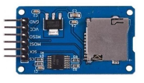
The microSD card module is designed to communicate with microSD cards over SPI. These modules provide the required hardware interface and pinout to connect SD cards with microcontrollers such as ESP32, Arduino, ESP8266, and Raspberry Pi. They are compatible with almost all microSD cards commonly used in mobile phones. However, they support a maximum capacity of 16 GB for microSD cards and 2 GB for standard SD cards.With the help of these modules, we can read and write data to and from SD cards through the SPI communication protocol. The microSD card module acts as a bridge between the 3.3 V logic of the microcontroller and the SD card, since the card itself operates at 3.3 V while microcontrollers often run at 5 V. The module contains a built-in voltage regulator and level-shifting circuitry to handle this conversion automatically.There are several different types of microSD card modules available in the market. The one used in this tutorial is a common 6-pin SPI module as shown below:
MicroSD card module
Pinout
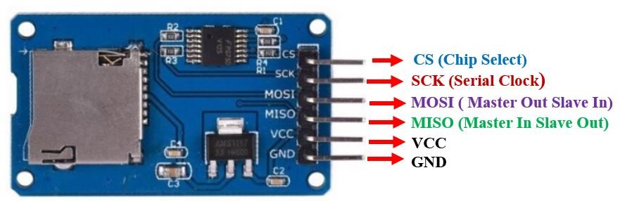
This microSD card module has 6 terminals consisting of SPI and power supply pins. The pinout is shown below, with a description of each pin.
Pinout of MicroSD card Module
Pin Name
Description
GND
Ground pin. Connect to the ground pin of the microcontroller.
VCC
Power supply pin. Accepts ~4.5V–5.5V. The module includes an onboard 3.3V voltage regulator. Connect to the 5V pin of the microcontroller.
CS
Chip Select pin for SPI communication. Pull LOW to activate the device.
MOSI
Master Out Slave In. SPI data input to the module from the microcontroller.
SCK
Serial Clock. SPI clock signal generated by the master device (Raspberry Pi Pico).
MISO
Master In Slave Out. SPI data output from the module back to the microcontroller.
MicroSD card module pin descriptions
MicroSD Card Module Interfacing with Raspberry Pi Pico
The following components are required for this project:
1 x Raspberry Pi Pico board
1 x MicroSD card (formatted as FAT32)
1 x MicroSD card module
Breadboard and jumper wires
Raspberry Pi Pico SPI Pins
Raspberry Pi Pico supports two SPI peripherals — SPI0 and SPI1. Both SPI module pins are accessible through multiple GPIO pins, giving you flexibility in wiring. The table below shows the available GPIO pins for each SPI controller:
SPI Controller
GPIO Pins
SPI0_RX (MISO)
GP0 / GP4 / GP16
SPI0_TX (MOSI)
GP3 / GP7 / GP19
SPI0_SCK
GP2 / GP6 / GP18
SPI0_CSn
GP1 / GP5 / GP17
SPI1_RX (MISO)
GP8 / GP12
SPI1_TX (MOSI)
GP11 / GP15
SPI1_SCK
GP10 / GP14
SPI1_CSn
GP9 / GP13
Before using SPI in your code, you must specify which GPIO pins you want to associate with the SPI peripheral. Each SPI controller supports both master and slave modes and is compatible with the following modes:
Motorola SPI Interface
TI Serial Interface
National Semiconductor Serial Interface
Each SPI controller has 8-deep TX and RX FIFOs and can be driven using interrupts or DMA for high-performance data transfer.
Schematic Diagram
Connect the microSD card module to Raspberry Pi Pico as shown in the table below. We are using the SPI1 peripheral on the Pico.
MicroSD Card Module
Raspberry Pi Pico
GND
GND
VCC
VBUS (5V)
CS
GP9 (SPI1_CSn)
MOSI
GP11 (SPI1_TX)
SCK
GP10 (SPI1_SCK)
MISO
GP8 (SPI1_RX)
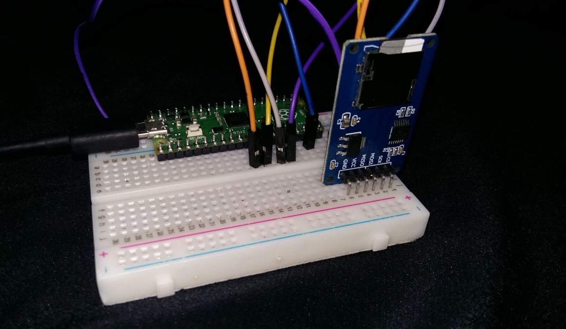
Connect the VCC terminal of the microSD card module to the VBUS (5V) pin of Raspberry Pi Pico. Both grounds must be connected together. The SPI data pins are connected according to the table above. You may also use SPI0 with its corresponding GPIO pins if preferred.
Raspberry Pi Pico with microSD card module connection diagram
Formatting the MicroSD Card
Before using the microSD card with Raspberry Pi Pico, it must be formatted as FAT32. The MicroPython sdcard driver only supports the FAT filesystem. Follow these steps to format your card:
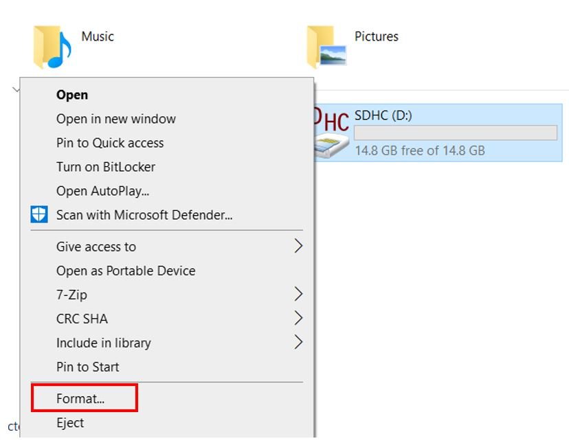
Insert your microSD card into your laptop or computer. Open This PC (Windows) or Finder (macOS), right-click the SD card icon, and select Format.
In the Format window, select FAT32 from the File System dropdown and click Start.
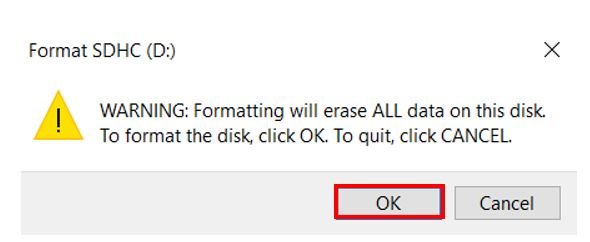
A warning message will appear, noting that formatting will erase all data on the card. Click OK to proceed.
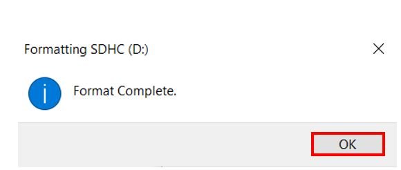
After a few seconds, the card will be formatted successfully. Click OK to finish.
Note for macOS users: Open Disk Utility, select your SD card, click Erase, choose MS-DOS (FAT) as the format, and click Erase.Important: Cards larger than 32 GB may default to exFAT during formatting. Always verify that FAT32 is selected, as exFAT is not supported by the MicroPython sdcard driver.
Installing the SD Card Library
For this project, we need the sdcard.py MicroPython driver. This library handles all low-level SPI communication with the SD card and exposes a block device interface that MicroPython’s VfsFat filesystem can use.Download the library from the official MicroPython GitHub repository: GitHub link.Open a new file in Thonny IDE, paste the library code (shown below), and save it to your Raspberry Pi Pico as sdcard.py inside the lib folder. If the lib folder does not exist, you can create it.sdcard.py
"""
MicroPython driver for SD cards using SPI bus.

Requires an SPI bus and a CS pin.  Provides readblocks and writeblocks
methods so the device can be mounted as a filesystem.

Example usage on pyboard:

    import pyb, sdcard, os
    sd = sdcard.SDCard(pyb.SPI(1), pyb.Pin.board.X5)
    pyb.mount(sd, '/sd2')
    os.listdir('/')

Example usage on ESP8266:

    import machine, sdcard, os
    sd = sdcard.SDCard(machine.SPI(1), machine.Pin(15))
    os.mount(sd, '/sd')
    os.listdir('/')

"""

from micropython import const
import time


_CMD_TIMEOUT = const(100)

_R1_IDLE_STATE = const(1 << 0)
# R1_ERASE_RESET = const(1 << 1)
_R1_ILLEGAL_COMMAND = const(1 << 2)
# R1_COM_CRC_ERROR = const(1 << 3)
# R1_ERASE_SEQUENCE_ERROR = const(1 << 4)
# R1_ADDRESS_ERROR = const(1 << 5)
# R1_PARAMETER_ERROR = const(1 << 6)
_TOKEN_CMD25 = const(0xFC)
_TOKEN_STOP_TRAN = const(0xFD)
_TOKEN_DATA = const(0xFE)


class SDCard:
    def __init__(self, spi, cs, baudrate=1320000):
        self.spi = spi
        self.cs = cs

        self.cmdbuf = bytearray(6)
        self.dummybuf = bytearray(512)
        self.tokenbuf = bytearray(1)
        for i in range(512):
            self.dummybuf[i] = 0xFF
        self.dummybuf_memoryview = memoryview(self.dummybuf)

        # initialise the card
        self.init_card(baudrate)

    def init_spi(self, baudrate):
        try:
            master = self.spi.MASTER
        except AttributeError:
            # on ESP8266
            self.spi.init(baudrate=baudrate, phase=0, polarity=0)
        else:
            # on pyboard
            self.spi.init(master, baudrate=baudrate, phase=0, polarity=0)

    def init_card(self, baudrate):

        # init CS pin
        self.cs.init(self.cs.OUT, value=1)

        # init SPI bus; use low data rate for initialisation
        self.init_spi(100000)

        # clock card at least 100 cycles with cs high
        for i in range(16):
            self.spi.write(b"\xff")

        # CMD0: init card; should return _R1_IDLE_STATE (allow 5 attempts)
        for _ in range(5):
            if self.cmd(0, 0, 0x95) == _R1_IDLE_STATE:
                break
        else:
            raise OSError("no SD card")

        # CMD8: determine card version
        r = self.cmd(8, 0x01AA, 0x87, 4)
        if r == _R1_IDLE_STATE:
            self.init_card_v2()
        elif r == (_R1_IDLE_STATE | _R1_ILLEGAL_COMMAND):
            self.init_card_v1()
        else:
            raise OSError("couldn't determine SD card version")

        # get the number of sectors
        # CMD9: response R2 (R1 byte + 16-byte block read)
        if self.cmd(9, 0, 0, 0, False) != 0:
            raise OSError("no response from SD card")
        csd = bytearray(16)
        self.readinto(csd)
        if csd[0] & 0xC0 == 0x40:  # CSD version 2.0
            self.sectors = ((csd[8] << 8 | csd[9]) + 1) * 1024
        elif csd[0] & 0xC0 == 0x00:  # CSD version 1.0 (old, <=2GB)
            c_size = csd[6] & 0b11 | csd[7] << 2 | (csd[8] & 0b11000000) << 4
            c_size_mult = ((csd[9] & 0b11) << 1) | csd[10] >> 7
            self.sectors = (c_size + 1) * (2 ** (c_size_mult + 2))
        else:
            raise OSError("SD card CSD format not supported")

        # CMD16: set block length to 512 bytes
        if self.cmd(16, 512, 0) != 0:
            raise OSError("can't set 512 block size")

        # set to high data rate now that it's initialised
        self.init_spi(baudrate)

    def init_card_v1(self):
        for i in range(_CMD_TIMEOUT):
            self.cmd(55, 0, 0)
            if self.cmd(41, 0, 0) == 0:
                self.cdv = 512
                return
        raise OSError("timeout waiting for v1 card")

    def init_card_v2(self):
        for i in range(_CMD_TIMEOUT):
            time.sleep_ms(50)
            self.cmd(58, 0, 0, 4)
            self.cmd(55, 0, 0)
            if self.cmd(41, 0x40000000, 0) == 0:
                self.cmd(58, 0, 0, 4)
                self.cdv = 1
                return
        raise OSError("timeout waiting for v2 card")

    def cmd(self, cmd, arg, crc, final=0, release=True, skip1=False):
        self.cs(0)

        buf = self.cmdbuf
        buf[0] = 0x40 | cmd
        buf[1] = arg >> 24
        buf[2] = arg >> 16
        buf[3] = arg >> 8
        buf[4] = arg
        buf[5] = crc
        self.spi.write(buf)

        if skip1:
            self.spi.readinto(self.tokenbuf, 0xFF)

        for i in range(_CMD_TIMEOUT):
            self.spi.readinto(self.tokenbuf, 0xFF)
            response = self.tokenbuf[0]
            if not (response & 0x80):
                for j in range(final):
                    self.spi.write(b"\xff")
                if release:
                    self.cs(1)
                    self.spi.write(b"\xff")
                return response

        self.cs(1)
        self.spi.write(b"\xff")
        return -1

    def readinto(self, buf):
        self.cs(0)

        for i in range(_CMD_TIMEOUT):
            self.spi.readinto(self.tokenbuf, 0xFF)
            if self.tokenbuf[0] == _TOKEN_DATA:
                break
            time.sleep_ms(1)
        else:
            self.cs(1)
            raise OSError("timeout waiting for response")

        mv = self.dummybuf_memoryview
        if len(buf) != len(mv):
            mv = mv[: len(buf)]
        self.spi.write_readinto(mv, buf)

        self.spi.write(b"\xff")
        self.spi.write(b"\xff")

        self.cs(1)
        self.spi.write(b"\xff")

    def write(self, token, buf):
        self.cs(0)

        self.spi.read(1, token)
        self.spi.write(buf)
        self.spi.write(b"\xff")
        self.spi.write(b"\xff")

        if (self.spi.read(1, 0xFF)[0] & 0x1F) != 0x05:
            self.cs(1)
            self.spi.write(b"\xff")
            return

        while self.spi.read(1, 0xFF)[0] == 0:
            pass

        self.cs(1)
        self.spi.write(b"\xff")

    def write_token(self, token):
        self.cs(0)
        self.spi.read(1, token)
        self.spi.write(b"\xff")
        while self.spi.read(1, 0xFF)[0] == 0x00:
            pass

        self.cs(1)
        self.spi.write(b"\xff")

    def readblocks(self, block_num, buf):
        nblocks = len(buf) // 512
        assert nblocks and not len(buf) % 512, "Buffer length is invalid"
        if nblocks == 1:
            if self.cmd(17, block_num * self.cdv, 0, release=False) != 0:
                self.cs(1)
                raise OSError(5)  # EIO
            self.readinto(buf)
        else:
            if self.cmd(18, block_num * self.cdv, 0, release=False) != 0:
                self.cs(1)
                raise OSError(5)  # EIO
            offset = 0
            mv = memoryview(buf)
            while nblocks:
                self.readinto(mv[offset : offset + 512])
                offset += 512
                nblocks -= 1
            if self.cmd(12, 0, 0xFF, skip1=True):
                raise OSError(5)  # EIO

    def writeblocks(self, block_num, buf):
        nblocks, err = divmod(len(buf), 512)
        assert nblocks and not err, "Buffer length is invalid"
        if nblocks == 1:
            if self.cmd(24, block_num * self.cdv, 0) != 0:
                raise OSError(5)  # EIO
            self.write(_TOKEN_DATA, buf)
        else:
            if self.cmd(25, block_num * self.cdv, 0) != 0:
                raise OSError(5)  # EIO
            offset = 0
            mv = memoryview(buf)
            while nblocks:
                self.write(_TOKEN_CMD25, mv[offset : offset + 512])
                offset += 512
                nblocks -= 1
            self.write_token(_TOKEN_STOP_TRAN)

    def ioctl(self, op, arg):
        if op == 4:  # get number of blocks
            return self.sectors
MicroPython Sketch: Read/Write to a File
Open Thonny IDE and go to File > New to open a new file. Copy the following code into the editor. This sketch initializes the microSD card, writes two lines of text to a file called data.txt, and then reads the file back to confirm the data was saved successfully.
import machine
import sdcard
import uos

# Configure the Chip Select pin
CS = machine.Pin(9, machine.Pin.OUT)

# Initialize SPI1 with the specified pins and baud rate
spi = machine.SPI(1,
                  baudrate=1000000,
                  polarity=0,
                  phase=0,
                  bits=8,
                  firstbit=machine.SPI.MSB,
                  sck=machine.Pin(10),
                  mosi=machine.Pin(11),
                  miso=machine.Pin(8))

# Initialize the SD card object
sd = sdcard.SDCard(spi, CS)

# Mount the FAT filesystem
vfs = uos.VfsFat(sd)
uos.mount(vfs, "/sd")

print("SD card mounted successfully!")
print("Files on SD card:", uos.listdir("/sd"))

# Create a file and write data to it
with open("/sd/data.txt", "w") as file:
    print("Writing to data.txt...")
    file.write("Welcome to microcontrollerslab!\r\n")
    file.write("This is a test\r\n")

print("Write complete.")

# Open the file and read the data back
with open("/sd/data.txt", "r") as file:
    print("Reading data.txt...")
    data = file.read()
    print(data)
How the Code Works
Let us go through each part of the code and understand what it does.
Importing Libraries
We start by importing the three modules needed for this project. The machine module provides access to hardware peripherals like SPI and GPIO pins. The sdcard module is the driver we installed earlier, and uos is MicroPython’s operating system module that handles filesystem operations such as mounting, listing directories, and file I/O.
import machine
import sdcard
import uos
Configuring the CS Pin
The Chip Select (CS) pin is used to activate or deactivate the SD card on the SPI bus. We configure GP9 as an output pin using the machine.Pin() constructor. Passing machine.Pin.OUT sets the pin direction to output. The CS line must be held HIGH when the SD card is not being accessed and pulled LOW when communication starts.
CS = machine.Pin(9, machine.Pin.OUT)
Initializing the SPI Interface
We initialize the SPI1 peripheral using machine.SPI(). The parameters specify the SPI channel (1), the baud rate (1 MHz), the clock polarity and phase (both 0, which is SPI Mode 0), the data frame size (8 bits), and the bit order (MSB first). The SCK, MOSI, and MISO pins are explicitly assigned to GP10, GP11, and GP8 respectively. Starting at a moderate baud rate of 1 MHz ensures compatibility with most SD cards during normal operation. The sdcard driver itself initializes communication at 100 kHz before switching to this higher speed.
The sdcard.SDCard() constructor takes the SPI object and CS pin as arguments and performs the full SD card initialization sequence. Internally, it sends CMD0 to reset the card, CMD8 to determine the card version (v1 or v2), CMD9 to read the Card Specific Data register, and CMD16 to set the block size to 512 bytes.
sd = sdcard.SDCard(spi, CS)
After initializing the SD card object, we create a FAT filesystem instance and mount it at the path /sd. Once mounted, we can access the card just like any other directory using standard Python file operations.
vfs = uos.VfsFat(sd)
uos.mount(vfs, "/sd")
Writing Data to a File
We use Python’s built-in open() function with the mode 'w' to open a file for writing. If the file does not already exist on the card, it will be created automatically. We use a with statement (context manager) so the file is automatically closed and flushed when the block exits, ensuring no data is lost.
with open("/sd/data.txt", "w") as file:
print("Writing to data.txt...")
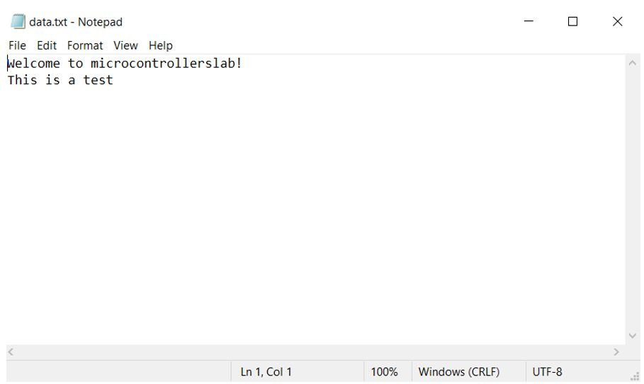
file.write("Welcome to microcontrollerslab!\r\n")
file.write("This is a test\r\n")
The \r\n at the end of each string is a Windows-style line ending (carriage return + newline), which ensures proper line breaks when the file is opened on a Windows computer.
Reading Data from a File
To verify that the data was written correctly, we reopen the file using mode 'r' (read) and call file.read() to load the entire contents into a string variable. We then print it to the Thonny shell terminal.
with open("/sd/data.txt", "r") as file:
    print("Reading data.txt...")
    data = file.read()
    print(data)
Demonstration
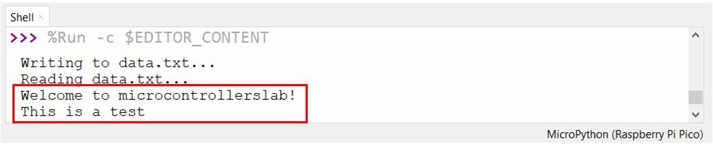
Save the code as main.py on your Raspberry Pi Pico and run it. You should see the following output in the Thonny shell terminal, confirming that the SD card was mounted, the file was written, and the content was read back successfully:
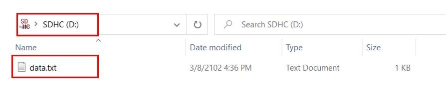
Remove the microSD card from the module and insert it into your computer. You should see data.txt in the card’s root directory.
Open the file to confirm the two lines of text were saved correctly:
Additional File Operations
Now that you have the SD card mounted and working, you can perform a variety of file operations using standard MicroPython (Python) syntax. Here are some common examples that extend what we covered above.To append data to an existing file without overwriting it, use mode 'a' instead of 'w'. This is particularly useful for data logging applications where you want to continuously add new entries without losing old ones:
with open("/sd/data.txt", "a") as file:
    file.write("New line appended!\r\n")
To list all files and directories on the card, use uos.listdir():
Always unmount the card before physically removing it to avoid filesystem corruption. Removing the card while a write operation is in progress can cause data loss or damage to the FAT directory structure.
Troubleshooting
If you encounter errors when running the code, refer to the common issues and solutions listed below.OSError: no SD card — This error appears when the SD card cannot be detected. Check all wiring connections, particularly VCC (5V), GND, MOSI, MISO, SCK, and CS. Confirm that the card is fully seated in the module’s socket. Try a different microSD card if the problem persists.OSError: couldn’t determine SD card version — The driver could not identify the card type. This often happens with very old or very new cards. Try a different card in the 2–16 GB range, and ensure it is formatted as FAT32.OSError: [Errno 19] ENODEV — The filesystem could not be mounted. This usually means the card is not formatted as FAT32. Reformat the card following the steps in the Formatting section above.Data appears corrupted or truncated — Always use a with statement or call file.close() explicitly after writing. Failing to close the file may leave data in the write buffer without committing it to the card.Long wires cause communication errors — SPI is sensitive to wire length and signal integrity at higher speeds. Keep all connections as short as possible, and consider reducing the baud rate to 400000 if you experience intermittent errors on longer wires.
Conclusion
In this tutorial, we learned how to interface a microSD card module with Raspberry Pi Pico using MicroPython and the SPI protocol. We covered the hardware connections, formatted the card as FAT32, installed the required sdcard.py driver, and wrote a complete MicroPython script to mount the filesystem, write data to a text file, and read it back. We also looked at additional file operations such as appending, listing directories, checking free space, and safely unmounting the card.This foundational knowledge opens the door to building more advanced projects such as sensor data loggers, configuration file managers, and even simple web servers that serve static files from the SD card. For a practical application, check out our companion tutorial on building a DHT22 data logger with a microSD card.You may also like to read these SD card guides:
1 thought on “Interface Micro SD Card Module with Raspberry Pi Pico”
>>> %Run -c $EDITOR_CONTENT
Traceback (most recent call last):
File “”, line 12, in
OSError: [Errno 19] ENODEV
>>>
Code (sdcard.py and runtime) multiple checks.
2G micro sd card….
Multiple modules(hardware)…
Multiple wiring checks… All good (even replace wires a time or two)
Mutiple sd card partitioning, formatting fat32 and fat16
Card reads fine on win and linux boxes.
Voltage to card checks to sd card module pins(all of those tried).
Same error message every time.
Code recognizes when the sd card is pulled.
Web search no help :-(.
Any thoughts appreciated.
Thanks MUCH!