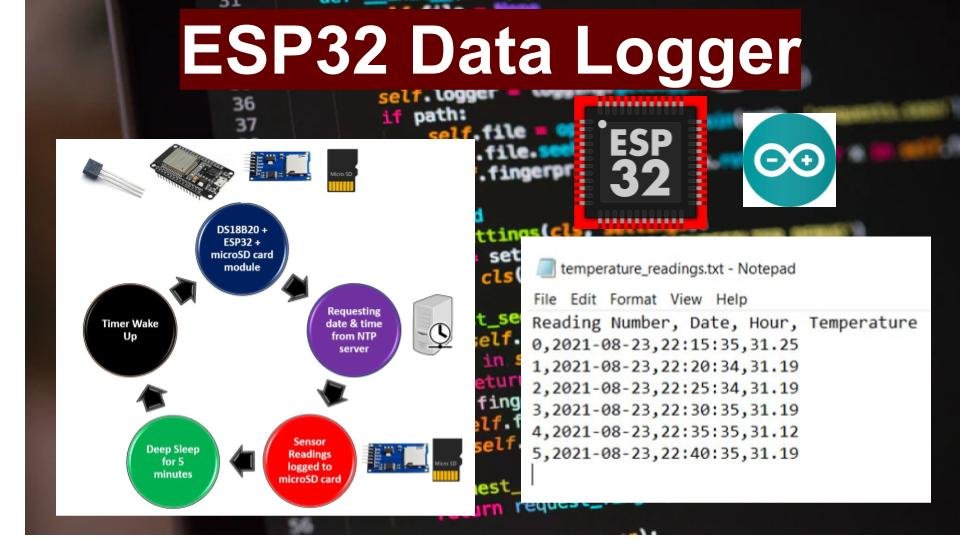
In this user guide, we will learn how to log DS18B20 temperature sensor readings along with timestamps to a microSD card using ESP32 and Arduino IDE. Furthermore, the current date and time will also be logged with each temperature sensor reading. We will use the ESP32 NTP server to request updated time stamps. In order to save battery, ESP32 will remain in sleep mode for most of the time and wake up from deep sleep after every 5 minutes. After wake up from deep sleep, ESP32 will take sensor reading, updated time from the NTP server, and logged the values to the MicroSD card.
Any preferred sensor, such as BME280, BME680, LM35, and MPU6050, can be used but for this article, we will use a ds18b20 sensor which will be used to measure the ambient temperature. The sensor readings will be accessed from the ds18b20 sensor connected with the ESP32 module. These readings will get updated on microSD card connected via the microSD card module to the ESP32 after every few minutes.
For a getting started guide to microSD card with ESP32, read the article: MicroSD Card Module with ESP32 using Arduino IDE
This article is divided into these sub-topics:
- Project Overview
- Introduction to ds18b20 sensor and connecting it with the ESP32 and the microSD card module
- Formatting the microSD card
- Setting up Arduino IDE for data logging temperature readings to microSD card (installing libraries, Arduino sketch and demonstration)
Recommended Components
The following components are used in this project or are helpful for building it with the ESP32.
| Component | How it’s used in this project | Buy on Amazon |
|---|---|---|
| ESP32 Development Board (DevKit V1) | Reads the DS18B20 sensor and logs timestamped temperature readings to the microSD card. | Check Price |
| Micro USB Cable | Connects the ESP32 to your computer for flashing the code and powering the board. | Check Price |
| Breadboard | Lets you wire the DS18B20 sensor and microSD card module to the ESP32 without soldering. | Check Price |
| Jumper Wires | Make the connections between the ESP32, the DS18B20 sensor and the microSD card module. | Check Price |
| DS18B20 temperature sensor | Measures the ambient temperature that is logged to the microSD card in this project. | Check Price |
| MicroSD card module (SPI) | Writes the temperature readings and timestamps to the microSD card over SPI. | Check Price |
| MicroSD card | Stores the logged temperature readings in a .txt file for later viewing. | Check Price |
As an Amazon Associate we earn from qualifying purchases. Prices and availability are accurate as of the date/time indicated and are subject to change.
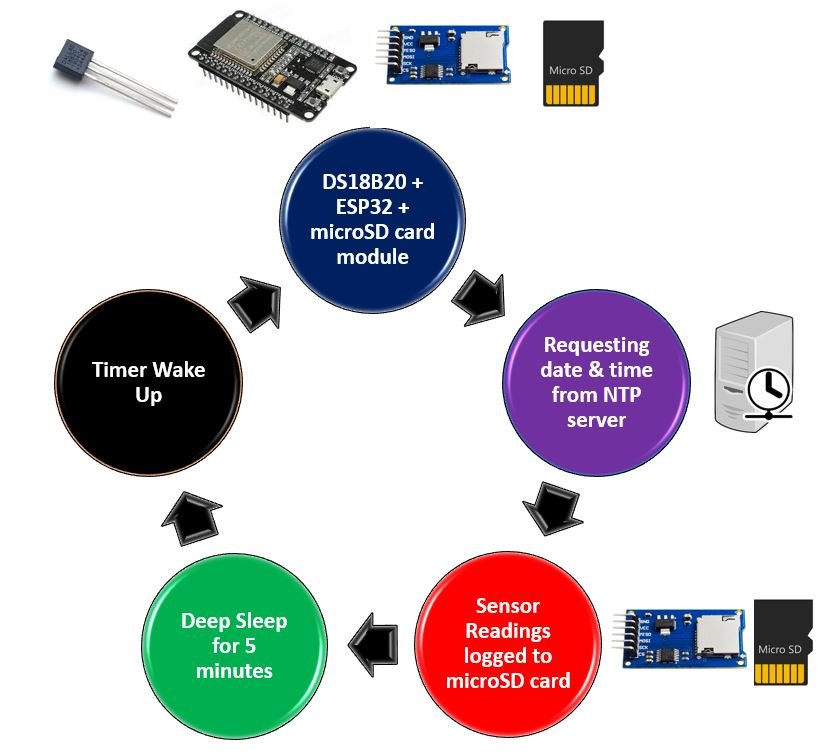
ESP32 Temperature Logging with SD Card Overview
The DS18B20 sensor will be connected to the ESP32 board through the GPIO pins which we will specify later. When the ESP32 development board boots, the DS18B20 sensor will get DS18B20 temperature readings. After that, a request will be made to the NTP server to access the current and date. The temperature reading along with its timestamp will then get logged to the microSD card and ESP32 goes to deep sleep for 5 minutes.
You can read more about ESP32 deep sleep here:
ESP32 Deep Sleep Mode and Wake Up Sources using Arduino IDE
After every 5 minutes, new sensor readings will get logged on the microSD card with its respective date and time. The rest of the time the ESP32 board will remain in deep sleep mode. This process will repeat indefinitely.
For this project we will require the following components:
Required Components
- ESP32 development board
- MicroSD card module
- MicroSD card
- DS18B20 temperature sensor
- 10k ohm resistor
- Connecting wires
- Breadboard
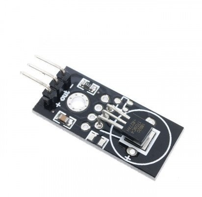
DS18B20 Introduction
DS18B20 is a temperature sensor that is single wire programmable in nature. It is widely used to measure the temperature of chemical solutions and substances which are present in a hard environment. One of the advantages of using this sensor is that we only require a single pin of our ESP boards to transfer data. Thus, it is extremely convenient to use with the micro-controller as we can measure multiple temperatures by using the least number of pins on our development board.
The table below shows some key characteristics of the ds18b120 sensor.
| Feature | Value |
|---|---|
| Operating Voltage | 3-5V |
| Temperature Range | -55°C to +125°C |
| Accuracy | ±0.5°C |
| Output Resolution | 9-12 bit |
Pinout Diagram
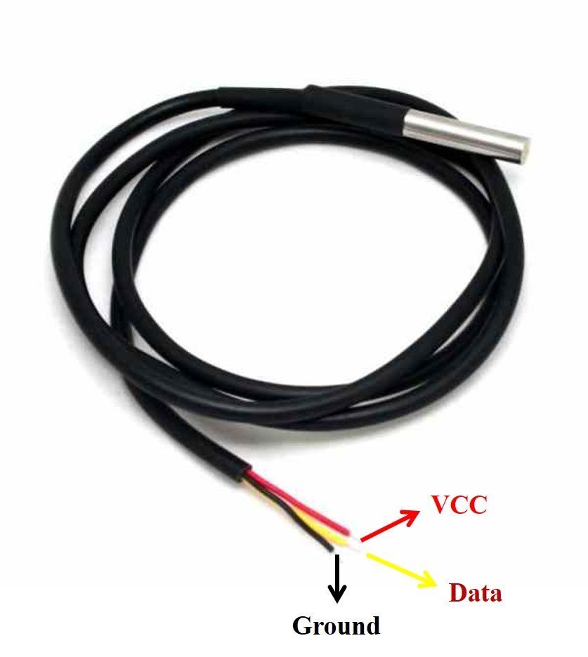
A waterproof version of this sensor is also available in the market. The following figures show the pinout of the DS18B20 sensors.
The following diagram shows the pinout of the normal DS18B20 temperature sensor.
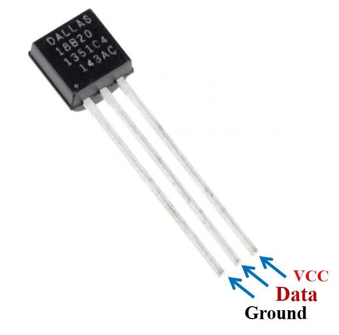
The table below lists the pin configurations:
| Pin | Description |
|---|---|
| VCC | This is the pin that powers up the sensor. It is 3.3V for ESP boards. |
| Data | This pin gives the temperature reading. |
| Ground | This pin is connected with the ground |
This temperature sensor also comes in a single package module which contains a sensor and a pull-up resistor. If you are using a module, you do not need to connect an external 4.7K ohm resistor. This is because the module already has an onboard pull-up resistor.
You can have a look at articles related to DS18B20 by accessing the links below:
- Single and Multiple DS18B20 with ESP32: Display Readings on OLED
- Interfacing Multiple DS18B20 with Arduino: Display Readings on OLED
- MicroPython: DS18B20 Web Server with ESP32/ESP8266(Weather Station)
Interfacing DS18B20 and microSD card module with ESP32 board
The connection of DS18B20 with the ESP32 board is very simple. The DS18B20 sensor can be powered in two different modes.
Normal Mode: The sensor is powered through an external source through the VDD pin and a pull-up resistor.
Parasite Mode: The sensor obtains power from its own data line. Hence, no external power supply is required.
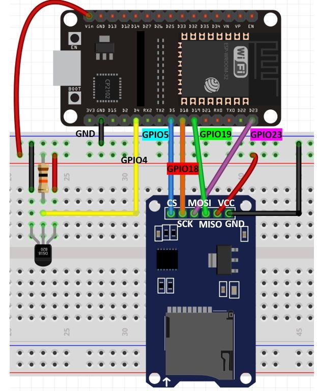
For this article, we will power the sensor in the normal mode. Thus, we have to connect the VCC terminal with Vin, ground with the ground (common ground), and the data pin of the sensor with an appropriate GPIO pin of ESP32 via a pull-up resistor. We are using GPIO4 for this project.
| DS18B20 sensor | ESP32 module |
| VCC | Vin |
| Data pin (middle pin) | GPIO4 |
| GND | GND |
Additionally, we will connect the VCC terminal of MicroSD card module with Vin of ESP32. Both grounds will be common. The default SPI GPIO pins of ESP32 are being used to connect with each of the remaining SPI terminals of the microSD card module.
The table below shows the connections between the two modules:
| MicroSD card module | ESP32 module |
| GND | GND |
| VCC | Vin |
| CS | GPIO5 |
| MOSI | GPIO23 |
| SCK | GPIO18 |
| MISO | GPIO19 |
The schematic diagram shows the connections between the ESP32 board, the DS18B20 sensor and the microSD card module.
Formatting the MicroSD card
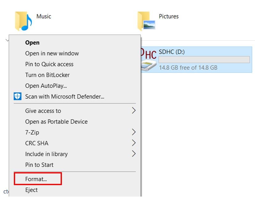
As we have to use our microSD card in Arduino IDE so we would have to format it as FAT32. We will have to follow a series of steps to accomplish it successfully.
- First, insert your microSD card in your laptop/computer. Now go to ‘This PC’ and click on SD card icon. Then click on Format by right clicking the SD card icon.
- The following window will appear. Select FAT32 from the dialog box of ‘File System’ and click on ‘START.’

- You will receive a warning message that formatting will erase all previous data saved on the microSD card. Click ‘OK.’
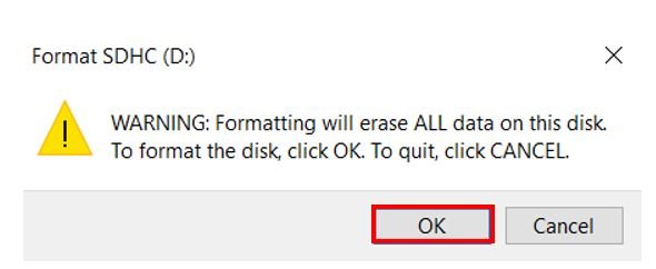
- After a few moments, your microSD card will be formatted successfully. Click ‘OK.’
Setting up Arduino IDE
Before we proceed further, you should make sure that you have the latest version of Arduino IDE installed on your system. Moreover, you should also install an ESP32 add-on in Arduino IDE. If your IDE does not have the plugin installed you can visit the link below:
Installing DS18B20 Libraries
To use the Dallas DS18B20 sensor we will have to install two libraries.
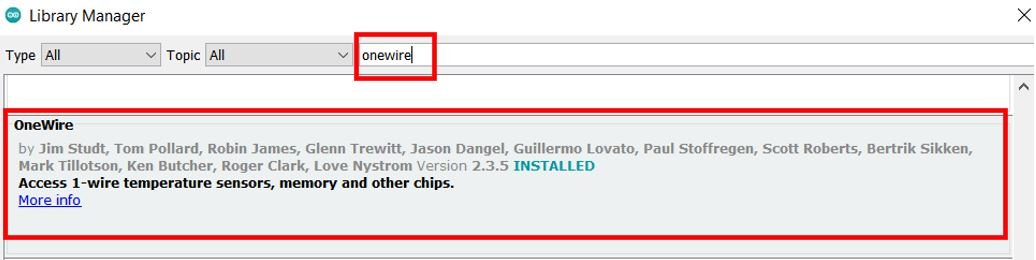
- OneWire library
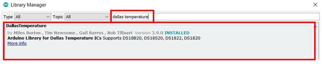
- DallasTemperature library
Follow the steps below to successfully install them. We will use the Library Manager in our Arduino IDE to install the latest versions of the libraries. Open your Arduino IDE and go to Sketch > Include Libraries > Manage Libraries. Type each library name in the search bar and install them both.
Installing NTPClient Library by Taranais
To request the current date and time from the NTP server we will use the NTPClient library by taranais available at Github. Follow the link:(https://github.com/taranais/NTPClient) to download it.
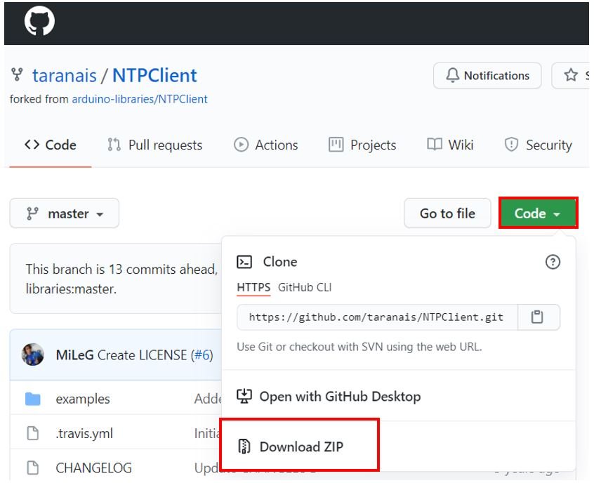
Click the Code button and go to the Download Zip option as highlighted in the figure. Your zip file will get downloaded to your computer right away. After the download is complete, extract the .zip file to the Arduino library folder. Make sure you rename the extracted file as ‘NTPClient.’ You can also go to Sketch > Include Library > Add .zip Library inside the IDE to add the library as well.
After installation of the libraries, restart your IDE.
Arduino Sketch – ESP32 Data Logging Readings to microSD card
Open your Arduino IDE and go to File > New to open a new file. Copy the code given below in that file.
This sketch will acquire temperature readings from DS18B20 sensor after every 5 minutes. Likewise, the time stamp will also be requested through the NTP server. This data will get displayed in the serial monitor as well as get saved in a .txt file on the microSD card. Additionally, we will put the ESP32 board in deep sleep mode after each set of data is acquired. This will led to a more efficient project.
#include "FS.h"
#include "SD.h"
#include <SPI.h>
#include <OneWire.h>
#include <DallasTemperature.h>
#include <WiFi.h>
#include <NTPClient.h>
#include <WiFiUdp.h>

uint64_t uS_TO_S_FACTOR = 1000000;
uint64_t TIME_TO_SLEEP = 300;

const char* ssid     = "Your_SSID";
const char* password = "Your_Password";

RTC_DATA_ATTR int sensor_data = 0;
String Data;

#define sensor_data_pin 4
OneWire oneWire(sensor_data_pin);
DallasTemperature sensors(&oneWire);

float temperature;
WiFiUDP ntpUDP;
NTPClient timeClient(ntpUDP);

String Date;
String day;
String Time;

void setup() {
  Serial.begin(115200);
  WiFi.begin(ssid, password);
  while (WiFi.status() != WL_CONNECTED) {
    delay(500);
    Serial.print(".");
  }
  Serial.println("");
  Serial.println("WiFi connected.");

  timeClient.begin();
  timeClient.setTimeOffset(18000);

  if(!SD.begin()) {
    Serial.println("Card Mount Failed");
    return;
  }
  uint8_t cardType = SD.cardType();
  if(cardType == CARD_NONE) {
    Serial.println("No SD card attached");
    return;
  }
  Serial.println("Initializing SD card...");
  if (!SD.begin()) {
    Serial.println("SD card initialization failed!");
    return;
  }

  File file = SD.open("/temperature_readings.txt");
  if(!file) {
    Serial.println("File does not exist");
    Serial.println("Creating file...");
    writeFile(SD, "/temperature_readings.txt", "Reading Number, Date, Hour, Temperature \r\n");
  }
  else {
    Serial.println("File exists");
  }
  file.close();

  esp_sleep_enable_timer_wakeup(TIME_TO_SLEEP * uS_TO_S_FACTOR);
  sensors.begin();
  obtainReadings();
  obtain_Date_Time();
  data_logging();

  sensor_data++;

  Serial.println("Sensor data logged successfully! Going to sleep");
  esp_deep_sleep_start();
}

void loop() {

}

void obtainReadings(){
  sensors.requestTemperatures();
  temperature = sensors.getTempCByIndex(0);
  Serial.print("Temperature: ");
  Serial.println(temperature);
}

void obtain_Date_Time() {
  while(!timeClient.update()) {
    timeClient.forceUpdate();
  }
  Date = timeClient.getFormattedDate();
  Serial.println(Date);

  int split = Date.indexOf("T");
  day = Date.substring(0, split);
  Serial.println(day);
  Time = Date.substring(split+1, Date.length()-1);
  Serial.println(Time);
}

void data_logging() {
  Data = String(sensor_data) + "," + String(day) + "," + String(Time) + "," +
                String(temperature) + "\r\n";
  Serial.print("Save data: ");
  Serial.println(Data);
  appendFile(SD, "/temperature_readings.txt", Data.c_str());
}

void writeFile(fs::FS &fs, const char * path, const char * message) {
  Serial.printf("Writing file: %s\n", path);

  File file = fs.open(path, FILE_WRITE);
  if(!file) {
    Serial.println("Failed to open file for writing");
    return;
  }
  if(file.print(message)) {
    Serial.println("File written");
  } else {
    Serial.println("Write failed");
  }
  file.close();
}

void appendFile(fs::FS &fs, const char * path, const char * message) {
  Serial.printf("Appending to file: %s\n", path);

  File file = fs.open(path, FILE_APPEND);
  if(!file) {
    Serial.println("Failed to open file for appending");
    return;
  }
  if(file.print(message)) {
    Serial.println("Message appended");
  } else {
    Serial.println("Append failed");
  }
  file.close();
}
How the Code Works?
Now let us understand how each part of the code works.
Installing Libraries
The first step is to include all the libraries that are necessary for this project. The FS library will be used for handling files, the SD library will be used for the microSD card functionality and the SPI library will be used as we are using SPI communication protocol between the ESP32 board and the microSD card module. Then, we will be including the OneWire and DallasTemperature libraries which we previously installed for the functionality of the DS18B20 sensor. The WiFi.h will help the ESP32 board to connect to the local network whose credentials that we will provide in the program code. Additionally, we will also include the NTPClient library which we previously installed so that we will be able to request the timestamp from the NTP server.
#include "FS.h"
#include "SD.h"
#include <SPI.h>
#include <OneWire.h>
#include <DallasTemperature.h>
#include <WiFi.h>
#include <NTPClient.h>
#include <WiFiUdp.h>
Adding the sleep time
We want our ESP32 module to go to deep sleep whenever we will not be accessing the sensor readings. As we are logging sensor readings after every 5 minutes thus, the module will go to sleep during that time. This will make our project very efficient. Specify the time in seconds. We have set it to 300 which means 300/60=5 minutes. Also, a micro second to second conversion factor is also defined which will be used later on in the program code.
uint64_t uS_TO_S_FACTOR = 1000000;
uint64_t TIME_TO_SLEEP = 300;
Setting Network Credentials
Next, we will create two global variables, one for the SSID and the other for the password. These will hold our network credentials which will be used to connect to our wireless network. Replace both of them with your credentials to ensure a successful connection.
const char* ssid = "Your_SSID";  //Write your SSID
const char* password = "Your_Password";  //Write your Password
Defining Variables
Next, we will define several variables. First, we will define an integer data type named ‘sensor_data.’ This will indicate the number of data (count) being logged in the microSD card e.g.(0,1,2…) This will be saved in the RTC memory of the ESP32 board so we will add ‘RTC_DATA_ATTR’ before defining it.
RTC_DATA_ATTR int sensor_data = 0;Next, is the string variable named ‘Data.’ This will hold the data that will get logged on the microSD card after every 5 minutes.
String Data;
Additionally, we will create three more string variables named ‘Date’, ‘day’ and ‘Time.’ This will hold the current day and time.
String Date;
String day;
String Time;
The float variable named ‘temperature’ will hold the sensor reading obtained from the DS18B20. This will get updated to a new value after every 5 minutes.
float temperature;Additionally, we will use the following lines of code to request the current timestamp from the NTP server.
WiFiUDP ntpUDP;
NTPClient timeClient(ntpUDP);
Defining sensor’s data pin
We will create a variable to store the GPIO pin through which the DS18B20 sensor’s data pin will be connected. We have used GPIO4 in this example.
#define sensor_data_pin 4Creating Instances for sensor
We will require the following instances as well to access the temperature readings. First, we will create a oneWire instance and use the sensor_data_pin as an argument inside it. Then we will call the DallasTemperature sensor and pass the oneWire reference which we created as an argument inside it.
OneWire oneWire(sensor_data_pin);
DallasTemperature sensors(&oneWire);
setup()
Inside the setup() function, we will open a serial connection at a baud rate of 115200.
Serial.begin(115200);The following section of code will connect the ESP32 module with the local network. We will call WiFi.begin() and pass the SSID and password variables inside it which we defined before.
After a successful connection has been established, the serial monitor will display the message “WiFi connected”.
 WiFi.begin(ssid, password);
  while (WiFi.status() != WL_CONNECTED) {
    delay(500);
    Serial.print(".");
  }
  Serial.println("");
  Serial.println("WiFi connected.");
Next, we will initialize the NTP server by using begin() method on timeClient. We will also set the time offset so that we obtain the correct time according to our country. We have specified the offset for Pakistan but you can change them according to your time zone to obtain the correct time.
For the GMT offset, click here to check for your time zone and add the offset in the program code by converting it in seconds.
For Pakistan, the UTC offset is +05:00 so in our code, we have specified the GMT offset which is the same as the UTC offset in seconds as 18000 (5*60*60).
 timeClient.begin();
 timeClient.setTimeOffset(18000); //Replace with your GMT offset (seconds)
Initializing microSD card
The following lines of code will initialize the microSD card using the begin() function on the SD filesystem. The begin() function takes in no argument. Thus, it will start the SPI communication using the default SPI CS pin that is GPIO5. To change the SPI CS pin you can pass the pin number as an argument inside the begin() function.
if(!SD.begin()) {
    Serial.println("Card Mount Failed");
    return;
  }
  uint8_t cardType = SD.cardType();
  if(cardType == CARD_NONE) {
    Serial.println("No SD card attached");
    return;
  }
  Serial.println("Initializing SD card...");
  if (!SD.begin()) {
    Serial.println("SD card initialization failed!");
    return;
  }
Creating .txt file
Next, we will open the temperature_readings.txt file on the microSD card using SD.open(). If the file does not exist, the message will get displayed in the serial monitor. The file will be created and its heading will be ” Reading Number, Date, Hour, Temperature”. This will be achieved by using the writeFile() function. After that, we will close the file using file.close().
File file = SD.open("/temperature_readings.txt");
  if(!file) {
    Serial.println("File does not exist");
    Serial.println("Creating file...");
    writeFile(SD, "/temperature_readings.txt", "Reading Number, Date, Hour, Temperature \r\n");
  }
  else {
    Serial.println("File exists");
  }
  file.close();
Enabling Timer Wake up
Next, we will enable the timer wake up. Using the following function, the ESP32 board will wake up from deep sleep mode. This function will take in the time in micro seconds as a parameter. Thus, we will pass TIME_TO_SLEEP (which is 5 minutes)* the conversion factor to insure that the argument inside the function is in micro seconds.
esp_sleep_enable_timer_wakeup(TIME_TO_SLEEP * uS_TO_S_FACTOR);Initializing DS18B20 sensor
We will call sensors.begin() to initialize the DS18B20 sensor.
sensors.begin();Next, we will call three functions that we will shortly explain. These will acquire the sensor readings and timestamp and log them on the microSD card.
obtainReadings();
obtain_Date_Time();
data_logging();
Increment the ‘sensor_data’ variable which denotes the count of the sensor readings.
sensor_data++;On the serial monitor, you will view that the sensor data was successfully logged and now the ESP32 board will go into deep sleep mode. The ESP32 board goes to deep sleep when esp_deep_sleep_start() function is called.
Serial.println("Sensor data logged successfully! Going to sleep");
esp_deep_sleep_start();
loop()
The loop() function is empty because it never reaches this part of the program code. The ESP32 goes into deep sleep.
void obtainReadings()
The obtainReadings() function takes in no parameter. It will access the temperature reading from the DS18B20 sensor and save it in the variable ‘temperature’ which we defined earlier. We will call the requestTemperatures() method. Then we will use the getTempCByIndex() function to retrieve the temperature in degree Celsius. Notice that we are passing 0 as a parameter inside the function. This is because we are using a single DS18B20 sensor. When using multiple sensors this value will increment for each additional sensor. We will display the temperature readings on the serial monitor after every 5 minutes.
void obtainReadings(){
  sensors.requestTemperatures();
  temperature = sensors.getTempCByIndex(0);
  Serial.print("Temperature: ");
  Serial.println(temperature);
}
void obtain_Date_Time()
The obtain_Date_Time() fuction also takes in no parameter. It will request the current date and time from the NTP server and save this value in ‘Date.’ This will be achieved by using timeClient.getFormattedDate(). In the serial monitor you will be able to view this timestamp. It will of the kind: 2021-08-23T22:15:35Z
Thus, we will have to split the date and the time. To do that we will first create an integer variable named ‘split.’ Then, save the date in the variable ‘day’ and the time in the variable ‘Time.’ These will be displayed in the serial monitor.
void obtain_Date_Time() {
  while(!timeClient.update()) {
    timeClient.forceUpdate();
  }
  Date = timeClient.getFormattedDate();
  Serial.println(Date);

  int split = Date.indexOf("T");
  day = Date.substring(0, split);
  Serial.println(day);
  Time = Date.substring(split+1, Date.length()-1);
  Serial.println(Time);
}
void data_logging()
The data_logging() function will log the data received from the DS18B20 sensor and the timestamp on the microSD card. This will be saved in the variable ‘Data.’ Data will consist of the sensor readings count (sensor_data), the current date (day), the current time (Time) and the sensor reading( temperature). This will get displayed in the serial monitor. To add this ‘Data’ at the end of our .txt in the microSD card, we will use the appendFile() function. This takes in the SD filesystem, the file path and the content which has to be added.
void data_logging() {
  Data = String(sensor_data) + "," + String(day) + "," + String(Time) + "," +
                String(temperature) + "\r\n";
  Serial.print("Save data: ");
  Serial.println(Data);
  appendFile(SD, "/temperature_readings.txt", Data.c_str());
}
writeFile()
This is the default writeFile() function that takes in three parameters. The first is the SD filesystem, the second is the file path and the third is the content which we want to write in the file.
void writeFile(fs::FS &fs, const char * path, const char * message) {
  Serial.printf("Writing file: %s\n", path);

  File file = fs.open(path, FILE_WRITE);
  if(!file) {
    Serial.println("Failed to open file for writing");
    return;
  }
  if(file.print(message)) {
    Serial.println("File written");
  } else {
    Serial.println("Write failed");
  }
  file.close();
}
appendFile()
To add some content at the end of a file, we will use the appendFile() function. This takes in the SD filesystem, the file path and the content which has to be added.
void appendFile(fs::FS &fs, const char * path, const char * message) {
  Serial.printf("Appending to file: %s\n", path);

  File file = fs.open(path, FILE_APPEND);
  if(!file) {
    Serial.println("Failed to open file for appending");
    return;
  }
  if(file.print(message)) {
    Serial.println("Message appended");
  } else {
    Serial.println("Append failed");
  }
  file.close();
}
Demonstration
Choose the correct board and COM port before uploading your code to the ESP32 board. Go to Tools > Board and select ESP32 Dev Module.

Next, go to Tools > Port and select the appropriate port through which your board is connected.

Now click on the upload button to upload code to ESP32. After that open the Arduino serial monitor and press the enable button on ESP32:

Open your serial monitor. You will be able to view the different messages.
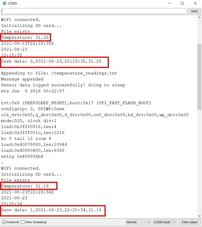
After a few minutes, take the microSD card out of the module and insert it in your system to view the temperature_readings.txt file.

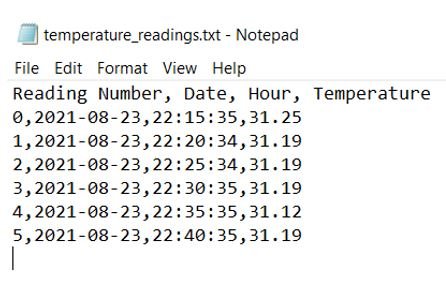
Open the .txt file. Inside it you will be able to view the temperature readings with their timestamps. We took readings for 25 minutes. Thus, we have a set of 6 readings after every 5 minutes.
Conclusion
In conclusion, we learned how to create a data logger to log sensor readings to MicroSD card using ESP32 and Arduino IDE. We used a DS18B20 sensor to access the current temperature readings that we logged on our microSD card. Additionally, we requested the current date and time as well through the NTP server for each sensor reading. In the next tutorial, we will show you how to create an ESP32 web server with files that will be saved on the microSD card.
L>S.,
best program I saw, was looking it for a couple of days and special the SD card getting connected.
By the way, the NTPClient library, I had the wrong one (without date) and therefore I got troubles with
getFormattedDate.
Thanks for writing and publishing this program,
GPostema