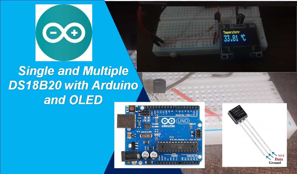
In this user guide, we will learn how to use a DS18B20 temperature sensor with an Arduino. We will see how to interface single and multiple sensors with Arduino. Additionally, we will also display the temperature readings on an SSD1306 OLED display.
This article is divided into these sub-topics:
- Introduction of DS18B20 sensor
- Install DS18B20 Library Arduino IDE
- Single DS18B20 sensor interfacing with Arduino
- Multiple DS18B20 sensors with Arduino
- Display DS18B20 sensor readings on OLED display with Arduino
We have similar guides with ESP32 and ESP8266 NodeMCU:
- DS18B20 with ESP8266 NodeMCU (Single/Multiple): Display Readings on OLED
- Single and Multiple DS18B20 with ESP32: Display Readings on OLED
Recommended Components
The following components are used in this project or are helpful for building it with the Arduino.
| Component | How it’s used in this project | Buy on Amazon |
|---|---|---|
| Arduino Uno R3 | The main microcontroller board that runs the sketch and reads the sensors/modules in this project. | Check Price |
| Breadboard | Lets you wire the components to the Arduino without soldering for quick prototyping. | Check Price |
| Jumper Wires | Connect the Arduino pins to the module and other parts on the breadboard. | Check Price |
| DS18B20 temperature sensor | The 1-Wire temperature sensor(s) read by the Arduino; multiple share one data line. | Check Price |
| 0.96″ SSD1306 OLED Display | Displays the DS18B20 temperature readings. | Check Price |
| Resistor Kit (220Ω/4.7kΩ) | Provides the 4.7kΩ pull-up resistor for the 1-Wire data line. | Check Price |
As an Amazon Associate we earn from qualifying purchases. Prices and availability are accurate as of the date/time indicated and are subject to change.
DS18B20 Introduction
It is a temperature sensor that is single wire programmable in nature. It is widely used to measure the temperature of chemical solutions and substances which are present in a hard environment. One of the advantages of using this sensor is that we only require a single pin of our Arduino board to get temperature samples. Therefore, it is extremely convenient to use with the microcontroller as we can use multiple DS18B20 temperature sensors by using only one pin on Arduino.
The table below shows some key characteristics of the ds18b120 sensor.
| Feature | Value |
|---|---|
| Operating Voltage | 3-5V |
| Temperature Range | -55°C to +125°C |
| Accuracy | ±0.5°C |
| Output Resolution | 9-12 bit |
Pinout Diagram
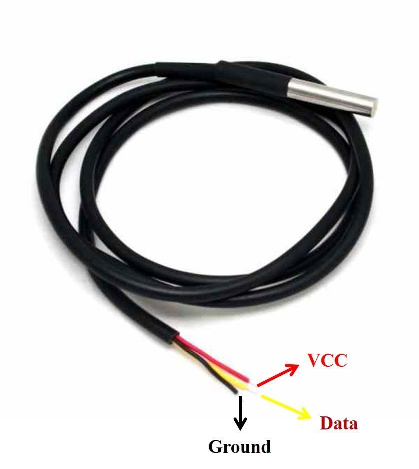
A waterproof version of this sensor is also available in the market. The following figures show the pinout of the DS18B20 sensors.
The following diagram shows the pinout of the normal DS18B20 temperature sensor.
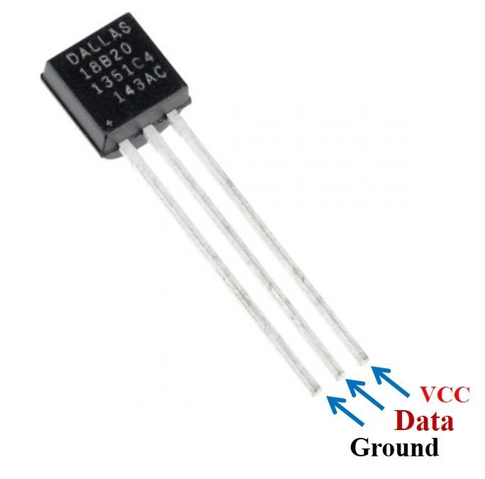
The table below lists the pin configurations:
| Pin | Description |
|---|---|
| VCC | This is the pin that powers up the sensor. It is 3.3V for ESP boards. |
| Data | This pin gives the temperature reading. |
| Ground | This pin is connected with the ground |
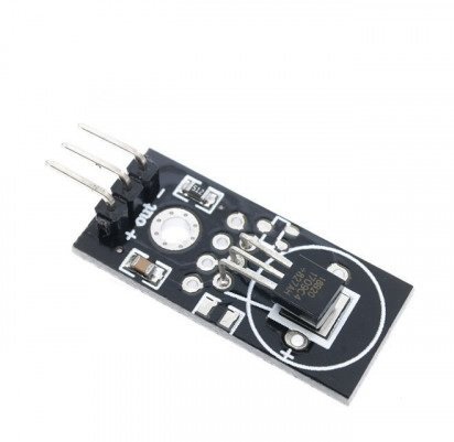
This temperature sensor also comes in a single package module which contains a sensor and a pull-up resistor. If you are using a module, you do not need to connect an external 4.7K ohm resistor. This is because the module already has an onboard pull-up resistor.
You can have a look at articles related to DS18B20 by accessing the links below:
- MicroPython: DS18B20 Web Server with ESP32/ESP8266(Weather Station)
- DS18B20 Temperature Module interfacing with arduino
Installing DS18B20 Library in Arduino IDE
The DS18B20 temperature sensor provides an output on a 1-Wire protocol which requires a complex Arduino sketch to be written from the scratch. Instead of reinventing the wheel, we can use the Dallas Arduino library. We can use simple functions to get temperature samples from the DS18B20 sensor with this library.
To use the Dallas DS18B20 sensor we will have to install two libraries.
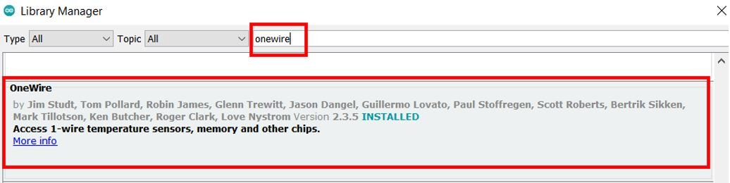
- OneWire library
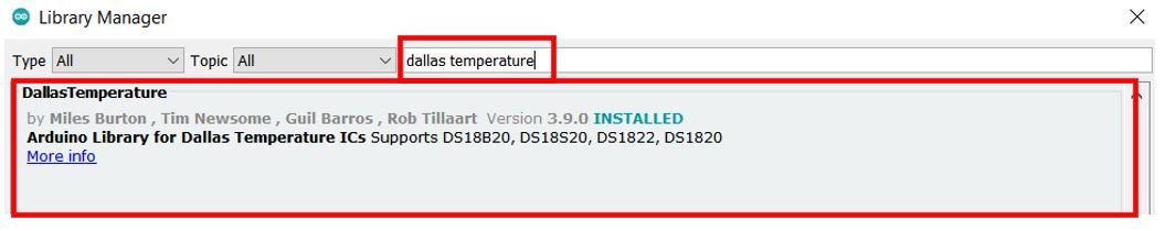
- DallasTemperature library
Follow the steps below to successfully install them. We will use the Library Manager in our Arduino IDE to install the latest versions of the libraries. Open your Arduino IDE and go to Sketch > Include Libraries > Manage Libraries. Type each library name in the search bar and install them both.
After installation of the libraries, restart your IDE.
Interfacing single DS18B20 sensor with Arduino board
The connection of DS18B20 with the Arduino board is very simple. The DS18B20 sensor can be powered in two different modes.
Normal Mode: The sensor is powered through an external source through the VDD pin and 4.7K ohm pull-up resistor.
Parasite Mode: The sensor obtains power from its own data line. Hence, no external power supply is required.
For this article, we will power the sensor in the normal mode. Thus, we have to connect the VCC terminal of the DS1B80 sensor with 3.3V, ground with the ground (common ground), and the data pin of the sensor with an appropriate GPIO pin of Arduino via a pull-up resistor. For this tutorial, we will use the D2 pin of Arduino for 1-wire protocol communication.
Required Components:
- Arduino
- DS18B20 sensor
- 4.7k ohm resistor
- Breadboard
- Connecting Wires
Arduino with DS18B20 Schematic Diagram
As you can see in the schematic diagram below, we have used DS10B20 in normal mode and powered the sensor with its VCC pin from the 3.3V pin of the Arduino board. Connect Arduino device with DS18B20 as shown in the schematic diagram below:
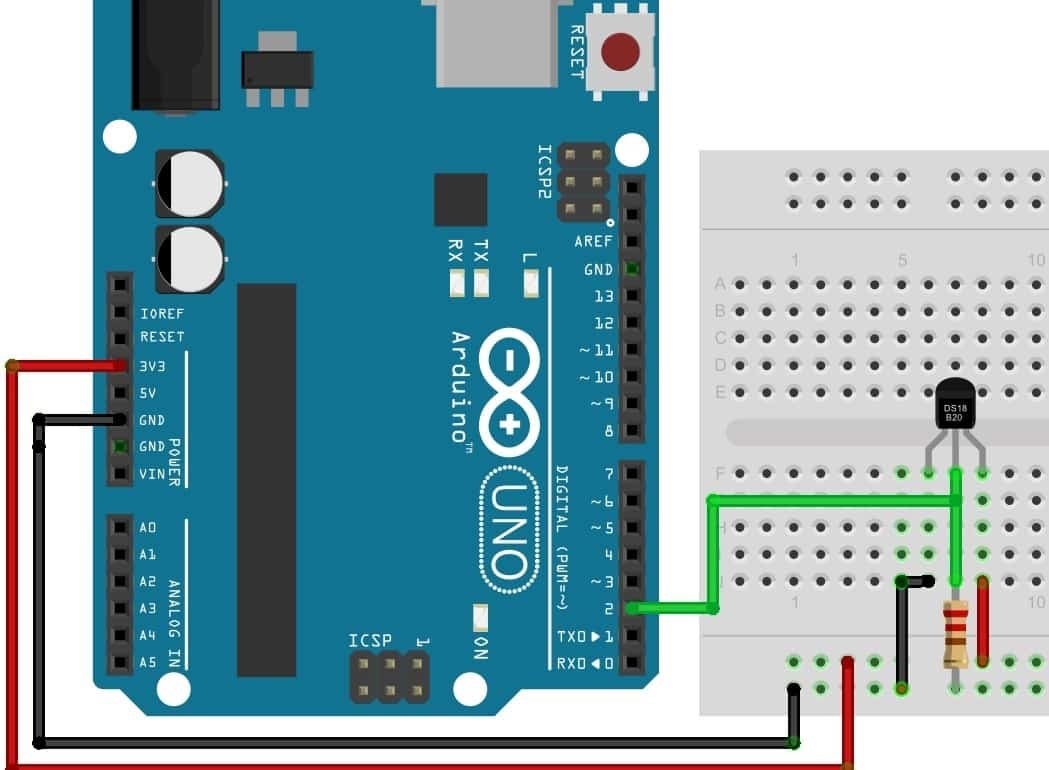
As you can see above, we have powered the sensor using the normal mode. The DS18B20 sensor has three terminals which we saw above in the pinout. The first terminal is grounded with the Arduino board. The data line of the sensor, which is the middle terminal, is connected through the D2 pin of Arduino through a pull-up resistor of 4.7k-ohm. You can choose any other digital pin as well. The third terminal is powered by 3.3V from the Arduino board.
Arduino Sketch (single DS18B20 sensor)
Open your Arduino IDE and go to File > New. A new file will open. Copy the code given below in that file and save it. This sketch will read the sensor data from the DS18B20 sensor and also print it on the Serial Monitor.
#include <OneWire.h>
#include <DallasTemperature.h>

const int SensorDataPin = 2;

OneWire oneWire(SensorDataPin);

DallasTemperature sensors(&oneWire);

void setup() {

  Serial.begin(115200);
  sensors.begin();
}

void loop() {
  sensors.requestTemperatures();
  float temperature_Celsius = sensors.getTempCByIndex(0);
  float temperature_Fahrenheit = sensors.getTempFByIndex(0);
  Serial.print("Temperature: ");
  Serial.print(temperature_Celsius);
  Serial.println(" ºC");
  Serial.print("Temperature: ");
  Serial.print(temperature_Fahrenheit);
  Serial.println(" ºF");
  Serial.println("");
  delay(10000);
}
How the Code Works?
Including Libraries
Firstly, we will include the necessary libraries. For this project, we are using two of them. As we have to connect our Arduino to the DS18B20 sensor thus we will require the following libraries: OneWire.h and DallasTemperature.h. These were the ones which we previously installed.
#include <OneWire.h>
#include <DallasTemperature.h>
Defining GPIO PIN
Secondly, we will create a variable to store the digital pin D2 through which the sensor’s data pin is connected. We have used GPIO14 in this example.
const int SensorDataPin = 2;Creating Instances
We will require the following instances as well to access the temperature readings. First, we will create a oneWire instance and use the SensorDataPin as an argument inside it. Then we will call the DallasTemperature sensor and pass the oneWire reference which we created above as an argument inside it.
OneWire oneWire(SensorDataPin);
DallasTemperature sensors(&oneWire);
setup() function
Inside the setup() function, we will open a serial connection at a baud rate of 115200. Moreover, we will call sensors.begin() to initialize the DS18B20 sensor as well.
void setup() {
  Serial.begin(115200);
  sensors.begin();
}
loop() function
In the infinite loop() function, we will obtain the temperature readings from the sensor and display them on OLED as well. Firstly, we will call the requestTemperatures() method. Then we will use the getTempCByIndex() function and getTempFByIndex() function to retrieve the temperature in degree Celsius and Fahrenheit respectively. Notice that we are passing 0 as a parameter inside the functions. This is because we are using a single DS18B20 sensor. When using multiple sensors this value will increment for each additional sensor.
sensors.requestTemperatures();
float temperature_Celsius = sensors.getTempCByIndex(0);
float temperature_Fahrenheit = sensors.getTempFByIndex(0);
Lastly, we will display the temperature readings with appropriate units on the serial monitor after every 10 seconds.
  Serial.print(temperature_Celsius);
  Serial.println("ºC");
  Serial.print(temperature_Fahrenheit);
  Serial.println("ºF");
  delay(10000);
Demonstration
Choose the correct board and COM port before uploading your code to the board.
Go to Tools > Board and select Arduino Module.

Next, go to Tools > Port and select the appropriate port through which your board is connected.
Click on the upload button to upload the code into the Arduino development board. After you have uploaded your code to the Arduino development board press its ENABLE button.
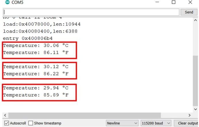
In your Arduino IDE, open up the serial monitor and you will be able to see the temperature readings. After every 10 seconds, newer readings get displayed.
Interfacing Multiple DS18B20 sensors with Arduino
Now, we will learn how to get temperature readings from multiple DS18B20 sensors connected with the Arduino board. As you know this temperature sensor uses a one-wire protocol to provide temperature samples. Each sensor comes with a unique 64-bit serial code which makes it easy to connect several DS18B20 sensors on the same one-wire bus. Hence, we will read the temperature readings from multiple DS18B20 sensors by connecting them through a single digital pin of Arduino.
Required Components:
We will need the following components to connect our Arduino board with the DS18B20 sensors.
- Arduino development board
- Three DS18B20 sensors
- 4.7k ohm resistor
- Breadboard
- Connecting Wires
Arduino with Multiple DS18B20 Sensors Schematic Diagram
As you can see in the schematic diagram below, we have used three DS10B20 sensors in normal mode and powered the sensor with its VCC pin from the 3.3V pin of the Arduino board. Connect Arduino device with DS18B20 as shown in the schematic diagram below:
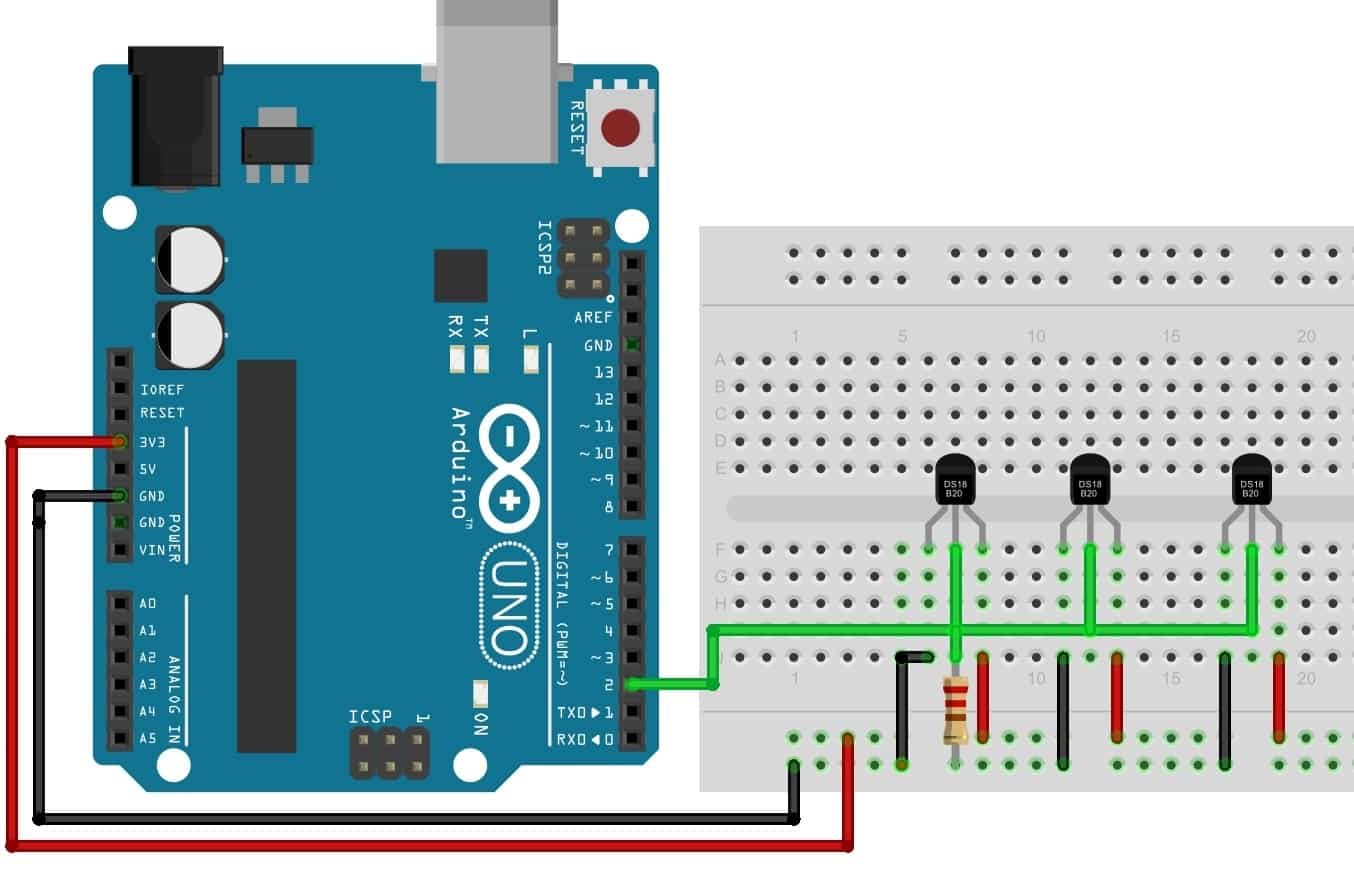
We will connect all the sensors in parallel. The VCC, ground, and data pins will be common. The GND terminal is grounded with the Arduino board. The data line of the sensors is connected through the D2 pin of Arduino through a pull-up resistor of 4.7k-ohm. You can choose any other digital pin as well. Also, we will require a single resistor for the whole bus. The VCC terminal is powered by 3.3V from the Arduino board.
Arduino Sketch (Multiple DS18B20 sensors)
Open your Arduino IDE and go to File > New. A new file will open. Copy the code given below in that file and save it. This sketch will identify the DS18B20 sensors and reads the sensor data from all three and print it on the Serial Monitor.
#include <OneWire.h>
#include <DallasTemperature.h>

#define ONE_WIRE_BUS 2

OneWire oneWire(ONE_WIRE_BUS);

DallasTemperature sensors(&oneWire);

int total_devices;
DeviceAddress sensor_address;

void setup(){
  Serial.begin(115200);
  sensors.begin();

  total_devices = sensors.getDeviceCount();

  Serial.print("Locating devices...");
  Serial.print("Found ");
  Serial.print(total_devices, DEC);
  Serial.println(" devices.");

  for(int i=0;i<total_devices; i++){
    if(sensors.getAddress(sensor_address, i)){
      Serial.print("Found device ");
      Serial.print(i, DEC);
      Serial.print(" with address: ");
      printAddress(sensor_address);
      Serial.println();
    } else {
      Serial.print("Found device at ");
      Serial.print(i, DEC);
      Serial.print(" but could not detect address. Check circuit connection!");
    }
  }
}

void loop(){
  sensors.requestTemperatures();

  for(int i=0;i<total_devices; i++){

    if(sensors.getAddress(sensor_address, i)){

      Serial.print("Temperature for device: ");
      Serial.println(i,DEC);

      float temperature_degreeCelsius = sensors.getTempC(sensor_address);
      Serial.print("Temp (degree celsius): ");
      Serial.println(temperature_degreeCelsius);

    }
  }
  delay(10000);
}


void printAddress(DeviceAddress deviceAddress) {
  for (uint8_t i = 0; i < 8; i++){
    if (deviceAddress[i] < 16) Serial.print("0");
      Serial.print(deviceAddress[i], HEX);
  }
}
How the Code Works?
Most of the parts in the code are similar to the ones which we discussed above. I will discuss the code where we are incorporating multiple sensors.
At the start of the sketch, we defined a variable of type int and named it ‘total_devices.’ Inside the setup() function we used sensors.getDeviceCount() to obtain the number of sensors that were successfully initialized. This number gets saved in the variable total_devices.
total_devices = sensors.getDeviceCount();We will print the number of devices on the Serial Monitor.
  Serial.print("Locating devices...");
  Serial.print("Found ");
  Serial.print(total_devices, DEC);
  Serial.println(" devices.");
This section of code uses a for loop to print the addresses for all the sensors attached. The unique address will be accessed through sensors.getAdress() with the sensor_address as the parameter. We will also call the printAddress() function with ‘sensor_address’ as the argument which will print the address of the sensors on the serial monitor.
for(int i=0;i<total_devices; i++){
    if(sensors.getAddress(sensor_address, i)){
      Serial.print("Found device ");
      Serial.print(i, DEC);
      Serial.print(" with address: ");
      printAddress(sensor_address);
      Serial.println();
    } else {
      Serial.print("Found device at ");
      Serial.print(i, DEC);
      Serial.print(" but could not detect address. Check circuit connection!");
    }
  }
loop() function
Inside the loop() function we will obtain the temperature readings from the sensor and display them on the serial monitor. We will use sensors.requestTemperatures() to request the temperature readings.
sensors.requestTemperatures(); Then we will use a ‘for loop’ to display the temperature for each sensor individually.
  for(int i=0;i<total_devices; i++){
    if(sensors.getAddress(sensor_address, i)){
      Serial.print("Temperature for device: ");
      Serial.println(i,DEC);
      float temperature_degreeCelsius = sensors.getTempC(sensor_address);
      Serial.print("Temp (degree celsius): ");
      Serial.print(temperature_degreeCelsius);

    }
  }
printAddress() function
The following function will print the address for each sensor.
void printAddress(DeviceAddress deviceAddress) {
  for (uint8_t i = 0; i < 8; i++){
    if (deviceAddress[i] < 16) Serial.print("0");
      Serial.print(deviceAddress[i], HEX);
  }
Demonstration
Choose the correct board and COM port before uploading your code to the board.
Go to Tools > Board and select Arduino Module.
Next, go to Tools > Port and select the appropriate port through which your board is connected.
Click on the upload button to upload the code into the Arduino development board. After you have uploaded your code to the Arduino development board press its ENABLE button.
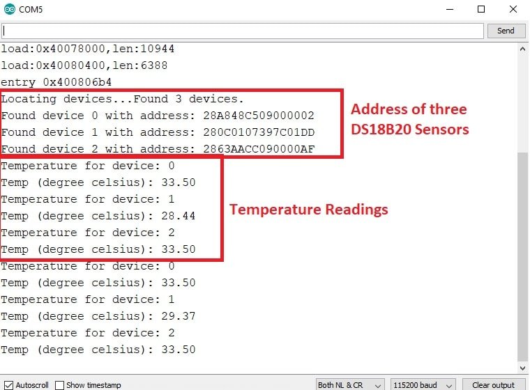
In your Arduino IDE, open up the serial monitor and you will be able to see the temperature readings for all three sensors. After every 10 seconds, newer readings get displayed.
Displaying DS18B20 Sensor values on OLED Display with Arduino IDE
In this section, we will see how to display Temperature values on a 0.96 SSD1306 OLED display using Arduino and Arduino IDE.
You can read this in-depth guide on OLED interfacing with Arduino:
OLED Display Interfacing with Arduino – Display Text, Draw shapes and Images
Installing OLED Libraries in Arduino IDE
To use the OLED display in our project, we have to install the Adafruit SSD1306 library and Adafruit GFX library in Arduino IDE. Follow the steps below to successfully install them.
Open Arduino IDE and click on Sketch > Library > Manage Libraries. Type ‘SSD1306’ in the search tab and install the Adafruit SSD1306 OLED library.

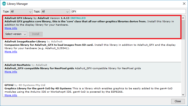
We will also require the Adafruit GFX library which is a dependency for SSD1306. Type ‘Adafruit GFX’ in the search tab and install it as well.
After installing the libraries, restart your IDE.
Arduino I2C Pins
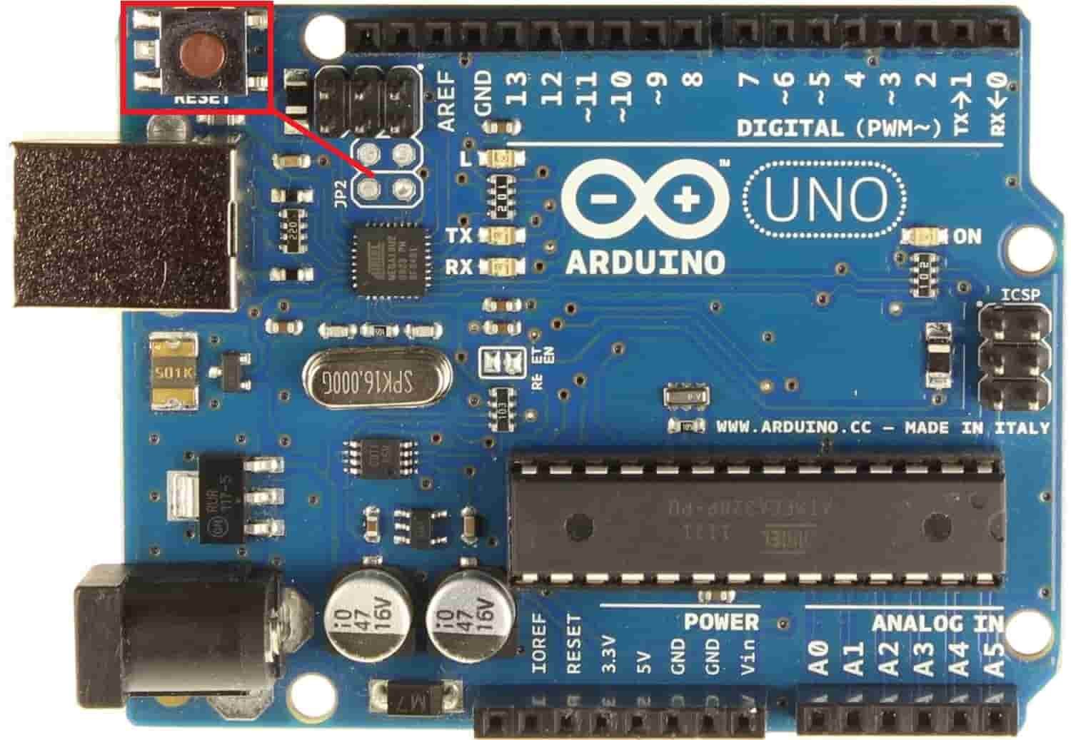
To interface OLED with Arduino, we need to use I2C pins of Arduino which are A4 (SDA) and A5 (SCL) pins. The I2C pins stated above are set in default. If we want to change the GPIO pins we have to set them in code. The diagrams below show the I2C pins of Arduino marked with different color rectangles.

Note: If we use other GPIO pins of Arduino for I2C communication, we can define other pins inside our Arduino sketch. We don’t have to use default I2C pins.
You can learn more about Arduino I2C communication here:
I2C Communication Between Two Arduino Boards
Connection Diagram– OLED with Arduino and DS18B20
Recommended Reading: OLED Display with ESP32 and ESP8266 in MicroPython
Required Components:
- Arduino board
- DS18B20 sensor
- 0.96-inch SSD 1306 OLED Display
- 4.7k ohm resistor
- Breadboard
- Connecting Wires
Assemble the circuit as shown in the schematic diagram below:
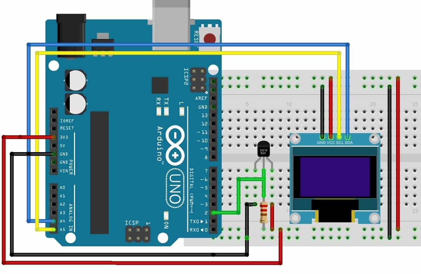
As you can see above, we have connected all the VCC terminals with a 3.3V pin of Arduino. The data pin of the DS18B20 sensor is connected with the D2 pin of the Arduino board. A 4.7K Resistor is used as a pull-up resistor & is connected between the data pin and VCC. The SCL terminal of the OLED is connected with A5 and the SDA terminal of the OLED is connected with the A4 pin of Arduino. The grounds of all three devices are common.
Arduino Sketch (Displaying Temperature Readings on OLED Display)
Open your Arduino IDE and go to File > New. A new file will open. Copy the code given below in that file and save it. This sketch will read the sensor data from the DS18B20 sensor and display it on the Serial Monitor as well as on the OLED.
#include <Wire.h>
#include <Adafruit_GFX.h>
#include <Adafruit_SSD1306.h>
#include <OneWire.h>
#include <DallasTemperature.h>

const int SensorDataPin = 2;

OneWire oneWire(SensorDataPin);
DallasTemperature sensors(&oneWire);

Adafruit_SSD1306 display = Adafruit_SSD1306(128, 64, &Wire, -1);

void setup() {
  Serial.begin(115200);

  if(!display.begin(SSD1306_SWITCHCAPVCC, 0x3D)) {
  Serial.println(F("SSD1306 allocation failed"));
  for(;;);
}
  delay(2000);
display.clearDisplay();
display.setTextColor(WHITE);

}

void loop() {
  delay(5000);
  display.setCursor(0,0);
   display.setTextSize(1);
  display.clearDisplay();

  sensors.requestTemperatures();
  float temperature_Celsius = sensors.getTempCByIndex(0);
  float temperature_F = sensors.getTempFByIndex(0);
  Serial.print("Temperature = "); Serial.print(temperature_Celsius); Serial.println(" *C");
  //display.print("Temperature: "); display.print(temperature_Celsius); display.println(" *C");
  display.setTextSize(1);
  display.setCursor(0,0);
  display.print("Temperature: ");
  display.setTextSize(2);
  display.setCursor(0,10);
  display.print(temperature_Celsius);
  display.print(" ");
  display.setTextSize(1);
  display.cp437(true);
  display.write(167);
  display.setTextSize(2);
  display.print("C");

  Serial.println();
  display.display();
  delay(2000);
}
How the Code Works?
Including Libraries
Firstly, we will include all the following libraries which are required for this project. Wire.h will allow us to communicate through the I2C protocol. Whereas the other libraries are the ones which we previously installed and are required for the proper functionality of the OLED display and the DS18B20 sensor.
#include <Wire.h>
#include <Adafruit_GFX.h>
#include <Adafruit_SSD1306.h>
#include <OneWire.h>
#include <DallasTemperature.h>
Defining DS18B20 sensor parameters
Secondly, we will create a variable to store the GPIO pin through which the sensor’s data pin is connected. We have used D2 in this example.
const int SensorDataPin = 2;We will require the following instances as well to access the temperature readings. First, we will create a oneWire instance and use the SensorDataPin as an argument inside it. Then we will call the DallasTemperature sensor and pass the oneWire reference which we created above as an argument inside it.
OneWire oneWire(SensorDataPin);
DallasTemperature sensors(&oneWire);
Defining OLED Display
We will initialize the display by creating an object and specifying the width, height, I2C instance (&Wire), and -1 as parameters inside Adafruit_SSD1306. -1 specifies that the OLED display which we are using does not have a RESET pin. If you are using the RESET pin then specify the GPIO through which you are connecting it with your development board.
Adafruit_SSD1306 display = Adafruit_SSD1306(128, 64, &Wire, -1);setup() function
Inside the setup() function, we will open a serial connection at a baud rate of 115200. Moreover, we will also initialize the OLED display. Make sure you specify the correct address of your display. In our case, it is 0X3D.
Serial.begin(115200);
  if(!display.begin(SSD1306_SWITCHCAPVCC, 0x3D)) {
  Serial.println(F("SSD1306 allocation failed"));
  for(;;);
The following lines of code will clear the display and set the text color to white.
display.clearDisplay();
display.setTextColor(WHITE);
loop() function
Inside the loop() function, we will display the temperature readings on the OLED display and the Serial Monitor.
We will use the setCursor() function to denote the x and the y axis position from where the text should start. We have passed (0,0) as the parameter hence the text starts from the upper left corner. THe clearDisplay() function will wipe off the previous readings from the display after each loop() so that new ones can be printed.
display.setCursor(0,0);
display.setTextSize(1);
display.clearDisplay();
sensors.requestTemperatures();
float temperature_Celsius = sensors.getTempCByIndex(0);
Serial.print("Temperature = ");
Serial.print(temperature_Celsius);
Serial.println(" *C");
display.print("Temperature: ");
display.print(temperature_Celsius);
display.println(" *C");
Serial.println();
display.display();
Demonstration
To see the demonstration of the above code, upload the code to Arduino. Before uploading the code, make sure to select the Arduino board from Tools > Board and also select the correct COM port to which the Arduino board is connected from Tools > Port.
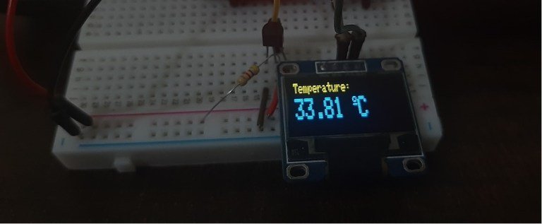
Once the code is uploaded to Arduino, open the serial monitor of Arduino IDE and set the baud rate to 115200. Finally, we can see the DS18B20 readings on the Arduino serial monitor and on the OLED display as shown below:
Conclusion
In conclusion, we learned how to interface single and multiple DS18B20 sensors with the Arduino development board. We used it to display temperature readings on an OLED display as well as on the Serial Monitor of Arduino IDE. Moreover, obtaining temperature readings from a single sensor as well as multiple sensors was also included.
You may also like to read other sensors guides with Arduino :
- BME280 with Arduino: Display Readings on OLED ( Arduino IDE)
- BME680 with Arduino: Display Gas, Pressure, Temperature and Humidity on OLED
- MPU6050 with Arduino – Display values on SSD1306 OLED
- Water Flow Sensor Interfacing with Arduino – Measure Flow Rate
- Voltage Sensor Module Interfacing with Arduino – DC Voltage Measurement
- SW-420 Vibration Sensor Module Interfacing with Arduino
- LSM303 Triple-Axis Accelerometer/Magnetometer Module with Arduino
- MPU9250 9-DOF MEMS Sensor Module Interfacing with Arduino
Hello,
I have a question.
Is it possible for you to change teh code?
so i can use it with 2 DS18B2O sensors
and that de result is shows on a oled 0.96 screen.
Now i have it with 1 sensor working but with 2 sensors
I dont get it working on the screen.
Please help me with modify the code for 2 on the screen.
many thanks.
Cheers,
Frans