Acs712 current sensor interfacing with Arduino for ac and dc current measurement: In this tutorial you will learn how to interface acs712 hall effect current sensor with arduino? And How to measure dc current using asc712 hall effect sensor and how to measure ac current using acs712 hall effect sensor? Acs712 is a cheap solution for current sensing in industry, power sector and communication applications. I will also show in this tutorial how to display measured value of currents on lcd and how to send this data to computer using serial communication of Arduino. ac current measurement and dc current measurement has many applications . Like in power systems protection, ac current measurement techniques are used to measure over load current for protection of transformers and generators. I have already posted a project on how to measure transformer health over internet which utilizes this technique of ac current measurement. And similarly, we use ac or dc current measurement circuits to design ac power meter or energy meters. It is also used in three phase induction motor current measurement for feedback control. 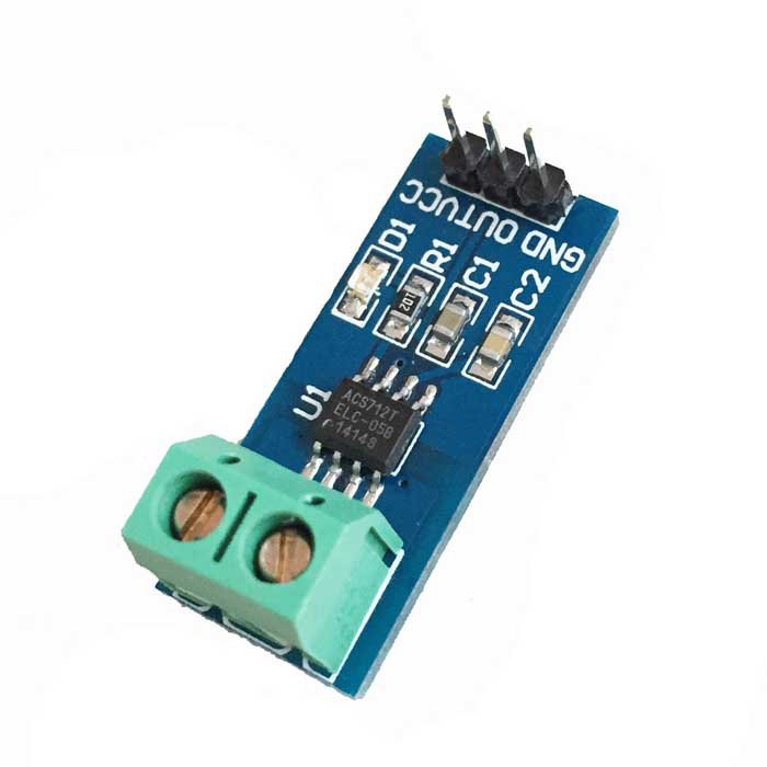
So this is all about introduction and some application of ac712 hall effect current sensor. Now lets start with main topic of this article that is how to measure ac and dc current using acs712 hall effect sensor. I will first give you introduction of ac712 current sensor, its working and types of acs712 current sensors. you may also like to check following projects:
- ac voltage measurement using Arduino
- ac current measurement using pic microcontroller
- ac power measurement using pic microcontroller
- power factor measurement using pic microcontroller
introduction to acs712 current sensor
Acs712 is hall effect based current sensor. It can measure both direct current and alternating current. It is a linear type sensor. This is very a famous integrated circuit designed by Allegro . It has features of noise cancellation, very high response time. Output error is about 1.5 percent but it can tackled with some intelligent programming and multiplying measured value with standard error of sensor. If you give dc current to its input , it will give proportional dc voltage at the output of sensor and if you give ac current at the input of acs712, it will give you proportional ac voltage at the output. Proportional term depends on the output sensitivity of the sensor. I will explain proportional sensitivity of acs712 sensor in later part of this article.

working of acs712 current sensor
This acs712 sensor consists of a linear hall effect circuit along with copper conduction path. Copper conduction path is located around the surface of the die. When ac or dc current passes through a copper conduction path, it produces magnetic field. This electromagnetic field interacts with hall effect sensor. Hall effect circuit converts this electromagnetic filed into proportional voltage either ac or dc depending on input current type. This output voltage is measured with the help of arduino or any microcontroller. After measuring this voltage, we convert it back into current using sensitivity equations which I will explain later on.
Pin diagram of acs712 hall effect current sensor
Pin out of acs712 current sensor is given below. Pin number 1 , 2 and 3 ,4 are used for current sampling. In other words. you will connect these pins in series with the load of which current you want to measure. 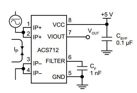 Pin number is ground connection of 5 volt power supply and pin number 6 is used to connect filter capacitor. One terminal of filter capacitor should be connected with pin number 6 and other terminal should be connected with ground. Similarly pin number 8 vcc is a power supply pin and you should connect dc 5 volt with it. Pin number 7 is the output pin of acs712 current sensor. From output pin, we will measure voltage with the help of arduino and we will see later on how to do it. Make sure to not connect your load in parallel with IP+ and IP+ it will damage your device and can also harm you if you are dealing with AC power supply or AC load.
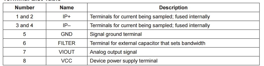
Types of acs712 current sensors
There are three types of acs712 sensors available according to current rating of sensors. Below tables provides the rating and all the details of three types of acs712 hall effect sensors. 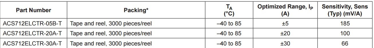
- ACS712ELCTR-05B: It sensor can measure current in the range of plus minus 5 Ampere and output sensitivity is 185mv/A . It mean the output voltage which will appear at the output pin of current sensor is 185 mili volt for every ampere passes through hall effect sensor. Similarly for other sensors but sensitivity is different for them.
- ACS712ELCTR-20A-T : It can measure 20 and -20 ampere current very easily and output sensitivity is 100mv/A.
- ACS712ELCTR-30A-T : It can measure 30 and -30 ampere current very easily and output sensitivity is 66mv/A.
How to measure current from output voltage of acs712 sensor?
To calculate current from output voltage of acs712 current sensor, you should make calculations according to following points:
- When there is no current flowing through the sensor, output voltage will be Vcc / 2. Where Vcc is power supply voltage given to acs712 to current sensor.
- if the Vcc = 5 volt, then the output voltage of current sensor will be equal to 2.5 when there is no current passing through a sensor.
- 2.5 volt is the offset voltage or base voltage of the sensor which should be subtracted from the measured voltage.
- The output voltage decreases when current starts passing through the sensor.
- So we can calculate dc current by using following commands:
Acs712 hall effect sensor interfacing with Arduino
figure below shows the connection diagram of interfacing acs712 current sensor with arduino. This sensor is also available in the form of module as shown in picture below: 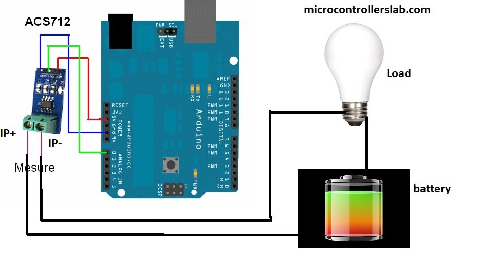
Vcc pin of current sensor module is connected with 5V pin of Arduino and Ground pin is connected with Ground pin of Arduino and output pin of current sensor module is connected with Analog channel 0 of Arduino which built in analog to digital converter of Arduino. Load is connected in series with IP+ and IP- pin and dc battery. You should make connections as shown above.
Dc current measurement using acs712 current sensor and arduino
Schematic and proteus simulation for dc current measurement is given below:
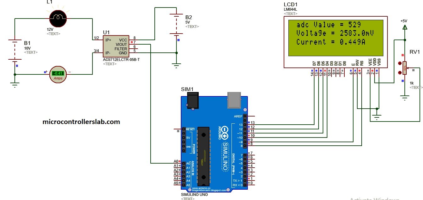
As shown on lcd first line is showing measured adc value and second line is showing voltage and third line is showing measured which is exactly the same current we measured with virtual ampere meter in proteus. Code for dc current measurement using acs712 hall effect sensor is given below.
Code for dc current measurement using acs712 current sensor
// include the library code:
#include <LiquidCrystal.h> //library for LCD

// initialize the library with the numbers of the interface pins
LiquidCrystal lcd(8, 9, 10, 11, 12, 13);

//Measuring Current Using ACS712

const int analogchannel = 0; //Connect current sensor with A0 of Arduino
int sensitivity = 185; // use 100 for 20A Module and 66 for 30A Module
int adcvalue= 0;
int offsetvoltage = 2500;
double Voltage = 0; //voltage measuring
double ecurrent = 0;// Current measuring

void setup() {
 //baud rate
 Serial.begin(9600);//baud rate at which arduino communicates with Laptop/PC
 // set up the LCD's number of columns and rows:
 lcd.begin(20, 4); //LCD order
 // Print a message to the LCD.
 lcd.setCursor(1,1);//Setting cursor on LCD
 lcd.print("MICROCONTROLLERSLAB");//Prints on the LCD
 lcd.setCursor(4,2);
 lcd.print(".com");
 delay(3000);//time delay for 3 sec
 lcd.clear();//clearing the LCD display
 lcd.display();//Turning on the display again
 lcd.setCursor(1,0);//setting LCD cursor
 lcd.print("Reading Values from");//prints on LCD
 lcd.setCursor(1,1);
 lcd.print("DC Current Sensor");
 lcd.setCursor(5,2);
 lcd.print("ACS 712");
 delay(2000);//delay for 2 sec
}

void loop() //method to run the source code repeatedly
{

 adcvalue = analogRead(analogchannel);//reading the value from the analog pin
 Voltage = (adcvalue / 1024.0) * 5000; // Gets you mV
 ecurrent = ((Voltage - offsetvoltage) / sensitivity);

//Prints on the serial port
 Serial.print("Raw Value = " ); // prints on the serial monitor
 Serial.print(adcvalue); //prints the results on the serial monitor

 lcd.clear();//clears the display of LCD
 delay(1000);//delay of 1 sec
 lcd.display();
 lcd.setCursor(1,0);
 lcd.print("adc Value = ");
 lcd.setCursor(13,0);
 lcd.print(adcvalue);

 Serial.print("\t mV = "); // shows the voltage measured
 Serial.print(Voltage,3); // the '3' after voltage allows you to display 3 digits after decimal point

 lcd.setCursor(1,1);
 lcd.print("Voltage = ");
 lcd.setCursor(11,1);
 lcd.print(Voltage,3);
 lcd.setCursor(17,1);
 lcd.print("mV");//Unit for the voltages to be measured

 Serial.print("\t ecurrent = "); // shows the voltage measured
 Serial.println(ecurrent,3);// the '3' after voltage allows you to display 3 digits after decimal point

 lcd.setCursor(1,2);
 lcd.print("Current = ");
 lcd.setCursor(11,2);
 lcd.print(ecurrent,3);
 lcd.setCursor(16,2);
 lcd.print("A"); //unit for the current to be measured
 delay(2500); //delay of 2.5 sec
}
The above code can be used for all of the three types of sensors 5 ampere, 20 ampere and 30 ampere current sensor. You just need to change the value of sensitivity in the code and rest of the code is self explanatory. Comments are also made in code for your understanding. I will also update this article on how to measure ac current with acs712 hall effect sensor.
Follow this guide for ac current measurement with AC712 and Arduino
Nice project arduino voltage/ current
it is fantastic and amayzing please send me if you have aproject or reserch on electrical power like power planning, fault analysis, power quality, satabilty etc
where is the code for Ac current?
hello sir, can i provide a variable dc voltage to this project and measure both the voltage and current simultaneusly
can i measure current of values 100kA using arduino?
Could be controlled DC relay by the output of this sensor?
When the current is passing through the sensor, it may change NC to NO or NO to NC.
Please explain me about the Arduino code. Thanks.
Hi. I connected the acs712 module to Arduino like the figure and tried your code, but it shows the module between negative 28 and 30 amps …… I do not know what to do.
good afternoon.
Please I’m doing a project that has to do with measuring current with current sensor.
The project is about power theft whereby you measure current before and after the meter.
I was you to help with a diagram the can make me measure the current after and before an energy meter.
And the code.
Thanks
when will you update the code for AC current and volt measurement and can you add power and energy measurement??
Nice article there guys
THANK YOU SIR NICE WORK
Very well explained and laid out, I will print this article to pdf and keep it in my reference material.
hi i want made a project for solar chrger controler
15 panel 320 watt voltage and current monitor in mobile blynk app
can you write a code for me.
i will pay for this