Today’s tutorial is about the interfacing of Rain drop sensor with Arduino. The rain sensor module is an easy tool for rain detection. It can be used as a switch when raindrop falls through the raining board and also for measuring rainfall intensity. The module features, a rain board and the control board that is separate for more convenience, power indicator LED and an adjustable sensitivity though a potentiometer. We will divide this tutorial in following sections:
- Working Principle of Raindrop Sensor
- Pin Configuration
- Specifications
- Circuit Diagram
- Testing the Circuit
- Applications
Rain Drop Sensor Module Introduction
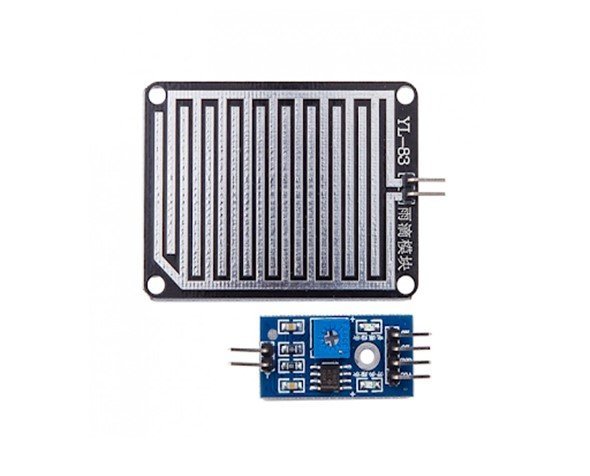
The rain drop sensor module is a smart and low-cost rain sensing device. It has two parts i.e. a rain sensing pad and a control board. The sensitive sensing pad detects any water present on it while the control board reads these signals and can also binarize them. The rain drop module has a major application in the automobile industry. It can be used to monitor the rain and send closure requests to shutters or windows whenever the rain is detected. The post is a guide to help make your own smart project.
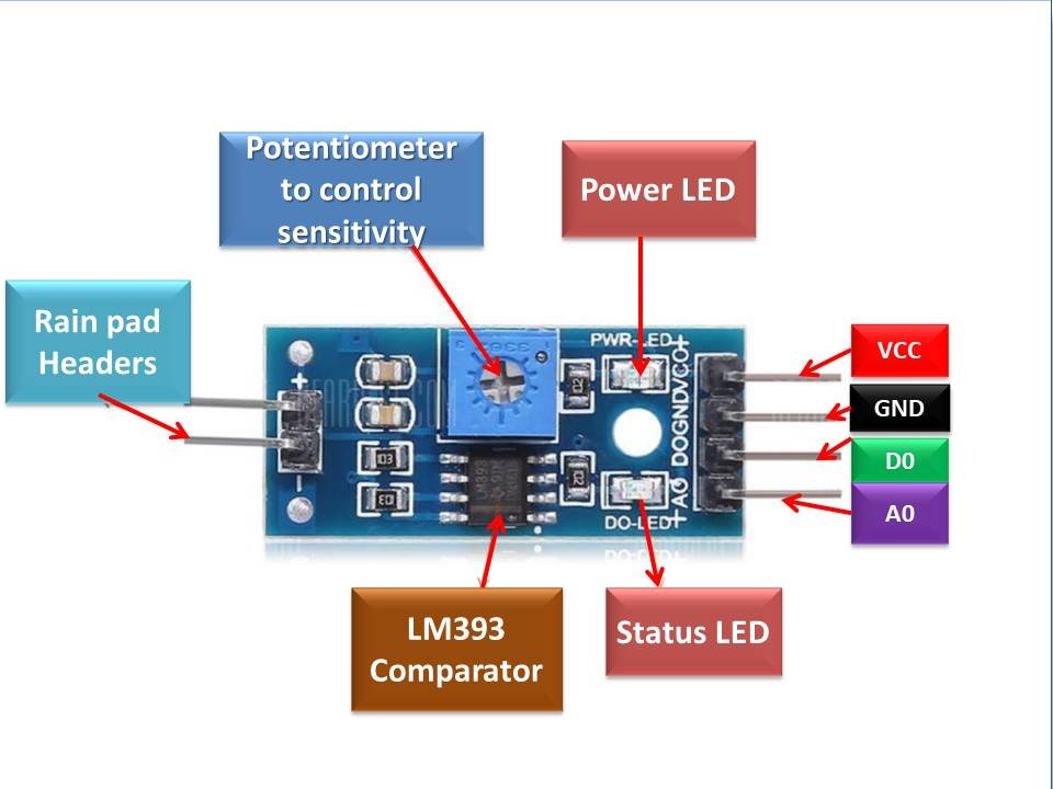
Rain Drop Pinout
The rain drop control sensor is embedded with LM393 voltage comparator, current limiting resistors to adjust signal states and divide the voltage and capacitors as biasing elements. The pinout of the Rain Drop Sensor module is as shown:

Pin Configuration
The rain drop sensor control board is available at 3.2cm x 1.4cm. The pin configuration in tabular are detailed below:
| Pin Name | Function |
|---|---|
| VCC | Positive power supply pin. It powers the sensor. |
| GND | Reference potential pin |
| D0 | Digital output pin. It gives the digital output of the internal comparator circuit. |
| A0 | Analog output pin. It serves to give analog signals between 0-5 Volts . |
| +/- | Rain pad Connecting Headers |
It consists of two parts one is a blackboard with nickel layers on it and the other is an integrated chip provided with some output pins. Board has 2 output pin and the chip has 6 pins.
Board Pins are
- +
- –
Rain Drop Sensor Working
A rain drop sensor is basically a board on which nickel is coated in the form of lines. It works on the principle of resistance. When there is no rain drop on board. Resistance is high so we get high voltage according to V=IR. When rain drop present it reduces the resistance because water is a conductor of electricity and the presence of water connects nickel lines in parallel so reduced resistance and the reduced voltage drop across it.
Copper Pads
The working of the rain sensor module is easy and straightforward. The sensor has a series of exposed copper paths that acts as a variable resistor whose resistance varies according to the amount of water on its surface. Usually, they are not connected but are bridged through the water. This resistance is inversely proportional to the amount of water. The more water on the surface of the rain pads the better is the conductivity and will result in a lower resistance. The sensor produces an output voltage through which it determines whether it is raining or not.
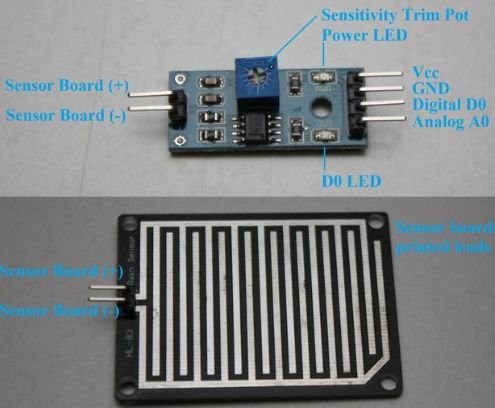
Sensor Module
The rain drop sensor module consists of a control sensor and a rain-sensing pad which can be connected to any microcontroller. The module produces an output voltage according to the resistance of the sensing pad and is given at the analog output pin. The same signal is also passed over to the LM393 high-precision comparator to digitize and is made available at the TTL digital output pin.
Control Circuit
In addition, the rain drop module has a potentiometer that is responsible for adjusting the output of the digital pin. To receive accurate readings, this potentiometer should be calibrated. The potentiometer is connected to the inverting end of the LM393 comparator and sets the reference or threshold voltage while the input analog voltage is applied to the non-inverting side of the comparator. The respective comparator compares both the voltages. This sets two conditions and gives the output accordingly. If the voltage given as an input exceeds the reference voltage then the comparator shows a high state.
Indication LED
Whereas if the threshold voltage is greater than the applied voltage then the comparator output will be low. Apart from these, the module has a power LED and a status LED. The power LED will light up when the module is powered while the status LED glows and indicates the digital output pin status.
Specifications of Raindrop Sensor
- Adopts high quality of RF-04 double sided material.
- Area: 5cm x 4cm nickel plate on side.
- Anti oxidation, anti-conductivity, with long use time.
- Comparator output signal clean waveform is good, driving ability, over 15mA.
- Potentiometer adjusts the sensitivity.
- Working voltage 5V.
- Output format: Digital switching output (0 and 1) and analog voltage output AO.
- With bolt holes for easy installation.
- Small board PCB size: 3.2cm x 1.4cm.
- Uses a wide voltage LM393 comparator.
Circuit Diagram
The functional diagram of the Rain Drop Sensor module for conceiving the knowledge of the internal connections of the module is provided below:

Interfacing with Arduino
This section deals with interfacing of Arduino UNO and Rain Drop Sensor module.
Following components will be used
- Arduino Board
- Rain sensor module
- Pin connectors
- USB cable
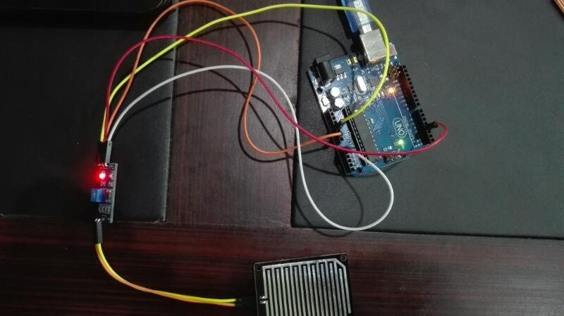
First make connections with Arduino and Rain drop sensor module.
- Rain Drop Black Board +ve with Integrated Chip +ve
- Rain Drop Black Board –ve with Integrated Chip –ve
- Vcc with Arduino Board +5V
- GND with Arduino Board GND
- Integrated Chip D0 with Arduino Board Digital pin 2
- Integrated Chip A0 with Arduino Board Analog pin A1

The analog output is used for the detection of rain drops with respect to the extent of rainfall. Connected to the 5Vpower supply, the LED will turn on when there is no rain drop on the nickel coated pads, and DO output is high. When dropping a little amount of water, DO output is low, the switch indicator will turn on. Brush off the water droplets, and when restored to the initial state, outputs high level. When no rain digital output is 1 and analog output gives 1023 max value. When rain is present digital output is 0 and analog output is much less than 1023. Using a potentiometer on-chip we can control the turning OFF point of a digital pin at some value of an analog pin.
Follow the steps to run program
- Connect the components based on the figure shown in the wiring diagram using pin connectors. VCC pin is connected to the 5V power supply, GND pin is connected to the GND, DO pin is connected to a digital I/O pin and the AO pin is connected to the analog output pin. Pin number will be based on the actual program code.
- After hardware connection, insert the sample sketch into the Arduino IDE.
- Using a USB cable, connect the ports from the Arduino to the computer.
- Upload the program.
- See the results in the serial monitor
Code
void setup()

{

  // put your setup code here, to run once:

  Serial.begin (9600);

  pinMode (2 , INPUT);

}

void loop()

{

  // put your main code here, to run repeatedly:

  int value = analogRead(A1);

  int digital = digitalRead(2);


  Serial.println (value);

  Serial.println (digital);

  delay(2000);

}
Rain Drop Sensor Analog and Digital Interface with Arduino
This section deals with interfacing of Arduino UNO and Rain Drop Sensor module.
Connection Diagram
- First, supply the power to the rain drop sensor. For that connect the ground pin of the rain drop sensor to the GND pin and the positive power supply pin to 3.3 / 5 Volts pin of the Arduino UNO.
- Connect the digital pin D0 to any of the digital pins of the Arduino.
- Connect the A0 pin to any of the six analog pins of the Arduino.
The wiring diagram is provided below:
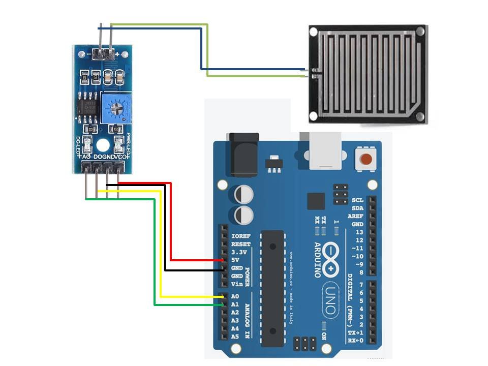
| Arduino UNO | Rain Drop Sensor Module |
|---|---|
| 5V(Red) | VCC |
| GND(Black) | GND |
| A1(Green) | A0 |
| A0 (Yellow) | D0 |
Arduino Code
The rain drop sensor module does not require any specific Arduino libraries for its interfacing with the Arduino microcontrollers. It can work perfectly using the built-in libraries in the Arduino IDE software.
The Arduino codes for Rain Drop Sensor module interfacing with Arduino with a digital and analog interface is given below:
Digital Interface Code
#define sensor_DO A0

void setup() {
  Serial.begin(9600);
}

void loop() {

  int val = digitalRead(sensor_DO);
  Serial.print("Digital Output: ");
  Serial.print(val);

  if (val == 1) {
    Serial.println("   Status: Dry");
  } else {
    Serial.println("   Status: Wet");
  }

  delay(1000);
}
Code Explanation using digital output pin
Defining pins: At the beginning of the code, we need to define a pin for the Arduino to take in the data from the rain drop module. We have assigned the Arduino pin A0 for this purpose.
void setup: We need the Serial monitor to showcase the results we obtain after processing the signal. So, the serial monitor with a baud rate of 9600 bps is initialized and activated in the void setup block.
void loop: This is the main body of the code. Here, first, we initialize an integer type variable i.e. “var”. The concerned variable reads the binary data from the A0 pin of the Arduino using the built in Arduino function called digitalRead().
An if condition is set up on this variable. According to this condition, if the var variable has a value 1 stored in it after reading the binary data, the module will display the status “Dry” on the serial monitor. If vice versa happens which means the var value is 0, it will eventually display the status “Wet” to warn about the water on its surface. This is followed by a delay of 1000 milliseconds.
Upload the code and observe the results. When the rain pad is dry, the comparator would be high and shows the dry status. The digital output LED will be off as well. And when water is sensed on its surface, it will show wet status with the status LED shining brightly.
Analog Interface Code
#define sensor_AO A1

void setup() {
  Serial.begin(9600);
}

void loop() {

  int val = analogRead(sensor_DO);
  Serial.print("Analog Output: ");
  Serial.print(val);

  delay(500);
}
Code Explanation using analog output pin
For using the analog output pin of the rain sensor module, we have defined the Arduino pin A1 to take the analog data. Similar to the last code, the serial monitor with a 9600 bps baud rate is initialized using the void setup section.
void loop: Here, the same variable “var” is used. But this time, it will store values corresponding to the analog signals which it will read using the predefined function of Arduino IDE, analogRead(). After reading the values, the Serial monitor will display them on the Serial monitor followed by a delay of 500 milliseconds.
Burn the code on the Arduino UNO microcontroller. The analog pin displays the value between 0 to 1024. In the dry condition, the serial monitor displays the maximum value of 1024 on the screen. Sprinkle some water on the pad and see the values decreasing instantly on the monitor. More the water on the surface, the lesser the analog value will be.
Applications
- On windscreen of car to automatically start the wipers
- On the roof of houses and offices to take necessary action during rain
- Home Automation projects
- Weather monitoring
- Intelligent Agriculture
- Automatic windshield wipers
what will be the threshold value of the rain drop sensor?
pls send answers fast
Sketch uses 2262 bytes (7%) of program storage space. Maximum is 32256 bytes.
Global variables use 188 bytes (9%) of dynamic memory, leaving 1860 bytes for local variables. Maximum is 2048 bytes.
How can I get sensor to not be so sensitive? Approximately 1 droplet of water will equal a flood and a few sprinkles equal a rain warning.