
This tutorial will view its pinout, configuration, features, specifications, interfacing,2D model, and applications.
TTP224 Touch Detector IC Pinout
The following diagram is the pinout of the integrated driver IC:


TTP224 Pin Configuration
The following table lists the pin configuration details of TIP224 touch detector IC.
| Number | Pin Name | Function |
|---|---|---|
| 1 | TP0 | Touch Key pin 1 |
| 2 | TP1 | Touch Key pin 2 |
| 3 | TP2 | Touch Key pin 3 |
| 4 | TP3 | Touch Key pin 4 |
| 5 | AHLB | Active high or low output pin |
| 6 | VDD | Positive Supply pin |
| 7 | VREG | Output internal Regulator pin |
| 8 | TOG | Output type choice pin |
| 9 | LPMB | Low power, fast mode choice pin |
| 10 | MOT1 | Key-on-time choice pin 2 |
| 11 | TPQ0D | Active-low-open-drain-output pin |
| 12 | TPQ0 | Direct Output pin 1 |
| 13 | TPQ1 | Direct Output pin 2 |
| 14 | TPQ2 | Direct Output pin 3 |
| 15 | TPQ3 | Direct Output pin 4 |
| 16 | SM | Single or multi-pin choice pin |
| 17 | OD | Output Open-drain choice pin |
| 18 | REGN | Internal Regulator enable/disable choice pin |
| 19 | VSS | Ground pin |
| 20 | MOT0 | Key-on-time choice pin 1 |
Features and Specifications
- Response time : 100msec-200msec
- Low Operating voltage: 2.5-5.5 Volts
- Operating current : 2.5 uA -9.0 uA
- Can adjust sensitivity externally by a capacitor (0-50pF)
- Provides a choice pin(LPMB) to select the fast or low power mode
- Select direct or toggle power mode
- Provides a choice pin to select active high or low output pin
- Make the output open-drain
- Inbuilt maximum on key time setting to return the system to the power-on state
- Inbuilt no diode protection circuit output pin(TPQ0D)
- Auto-calibration attribute of 4.0 sec if no touched is detected
- Touch stability with a stability time of 0.5sec
How to set the Modes of Output pin?
To set the mode of the output, we are facilitated with three pins. AHLB gives a choice to select whether the output pins should be either direct active high or active low. Similarly, TPQ0, TPQ1, TPQ2, and TPQ3 output pins can toggle if the TOG pin is enabled. Moreover, OD makes the output pins as Open-drain if enabled.
The chart shown below should be put into consideration to set the output combinations:

How to connect Touchpads and TTP224
The schematic below shows the connections of touchpads to TTP224 four-channel detector IC:
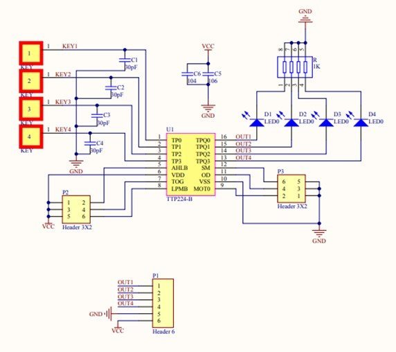
While designing a printed circuit board, successive points should be kept in mind for better performance:
- Power supply stability is important.
- The material covering PCB should not be metallic or electric.
- Make use of filters and capacitors to minimize input noise.
- C5 and C6 should be placed in the closest proximity of TTP224.
- Place touchpads close to the IC
- To control sensitivity over a vast range of temperatures, use either NRO or X7R capacitor.
Interfacing with Arduino
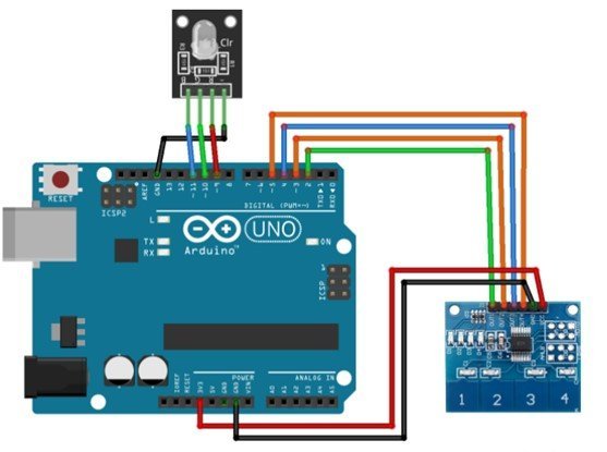
Interfacing TTP224 Four-Channel Touch IC with Arduino is straightforward and easy. The wiring diagram is shown above, and the pin configuration is as follows:
| TTP224 Module | Arduino UNO |
|---|---|
| GND | GND |
| VCC | +3V |
| OUT1 | D2 |
| OUT2 | D3 |
| OUT3 | D4 |
| OUT4 | D5 |
| RGB LED(common cathode) | Arduino UNO |
|---|---|
| GND | GND |
| R | D9(PWM) |
| G | D10(PWM) |
| B | D11(PWM) |
In this circuit, we power the LEDs through a 3v Arduino pin, but if an external power source is used, one must connect the ground of the Arduino to the ground of the power. The TTP224 module has respective status pins for its touchpad keys. The inbuilt status pin will indicate which key is touched. After making connections, upload the Arduino code. When any key is touched, the LED flashes a color according to the code, and the serial monitor will display the current state of the key. The results can be seen through the LED and Serial Monitor as well.
Arduio Code
#define PAD1 2 //Buttons pins
#define PAD2 3
#define PAD3 4
#define PAD4 5

//Arduino pins to which RGB LED connected
#define RED_LED 9
#define GREEN_LED 10
#define BLUE_LED 11

// Variables to store PWM duty cycle for each LED

int Red=0, Blue=0, Green=0; //Color values to be affected to the RGB

//Boolean variable to store pad state

bool PAD1_State, PAD2_State, PAD3_State, PAD4_State;


void setup() {

  Serial.begin(9600);        //Set Serial communication

  pinMode(PAD1,INPUT);    //Set pin modes
  pinMode(PAD2,INPUT);
  pinMode(PAD3,INPUT);
  pinMode(PAD4,INPUT);

  pinMode(RED_LED,OUTPUT);
  pinMode(GREEN_LED,OUTPUT);
  pinMode(BLUE_LED,OUTPUT);

}

void loop() {

  Serial.print(Red);     //Display the colors values on the serial monitor
  Serial.print("\t");
  Serial.print(Green);
  Serial.print("\t");
  Serial.println(Blue);


  PAD1_State = digitalRead(PAD1); //Read the buttons states
  PAD2_State = digitalRead(PAD2);
  PAD3_State = digitalRead(PAD3);
  PAD4_State = digitalRead(PAD4);

  analogWrite(RED_LED,Red);       //Write the values on the RGB
  analogWrite(GREEN_LED,Green);
  analogWrite(BLUE_LED,Blue);

  if(PAD1_State == HIGH)   //Button 1 controls the RED, 2 Green and 3 Blue
     Red+= 20;                //Everytime you press the value gets incremented by 20 you can change as you want
  if(Red >= 255)              //If it exceeds the limit it will be brought back to 0
     Red=0;

   if(PAD2_State == HIGH)
   Green+= 20;
  if(Green >= 255)
   Green=0;

   if(PAD3_State == HIGH)
   Blue+= 20;
   if(Blue >= 255)
   Blue=0;

   if(PAD4_State == HIGH){ //Button 4 resets the value to 0

    Red=0;
    Green=0;
    Blue=0;

   }
  delay(100); //To avoid that one touch gets counted as 10 or more, although 100 is pretty big you can reduce it and test
}
TTP224 Alternative Options
- TTP229
- TTP226
- ADS7843
Applications
- Substitutes for traditional buttons
- Different consumer products
- Smart control
2D Diagram
The following figure shows the 2d model of TTP224 Four-Channel Touch IC. It shows us the physical dimensions of the components needed when a PCB card is designed.

Datasheet
The link to the datasheet is given below to see more details and specifications of the TTP224 Four-Channel Touch IC Detector.