WS2812B is the most popular addressable RGB LED. Whether used for decorations or hobby projects, they are used for their easiness, bright colors, low required voltage. Most importantly, it contains an internal integrated driver that helps to control the color and brightness of RGB LED with a programmable feature. This programmable feature makes it smart which in turn aids in displaying different visual effects.

In this tutorial, we will have a look at its pinout, configuration, features, specifications, working, interfacing, 2D model, and its applications.
WS2812B Introduction
WS2812B is an intelligent control RGB LED and control unit fabricated in a 5050 package. Each addressable led has its own driver IC, which provides the charge to control the color and brightness independently according to one’s own need.
WS2812B Pinout
The following diagram shows the pinout of WS2812B Addressable RGB led. Each unit (pixel) has three LEDs(one red, one green, and one blue) and a driver IC to control the color and the luminosity of the led. It consists of four pins. A power supply pin, a ground pin, and 2 data pins, one for the input and the other for the output.
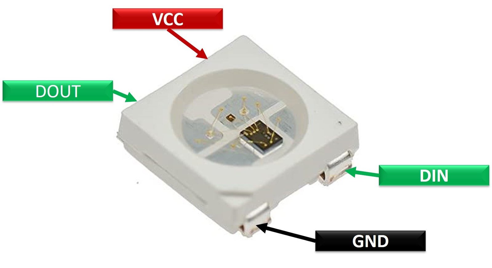
Pin Configuration Details
The pin configuration details are listed below in the tabular form:
| Number | Name | Function |
|---|---|---|
| 1 | VDD | Power supply pin |
| 2 | DOUT | Input data pin |
| 3 | VSS | Ground pin |
| 4 | DIN | Output data pin |
WS2812B RBG LED Features and Specifications
- Power supply voltage(VDD) : +3.5 to +5.3Volts
- Input signal voltage : -0.5 to VDD+0.5Volts
- Input signal current: 1uA
- Supply Capacitance: 15 pF
- Operational Frequency: 400Hz
- Data transmission speed: 800Kbps
Some of the cool features of WS2812B are :
- Reverse biased voltage protection that is the driver IC is not damaged even if the power supply is connected in reverse.
- It has a power and electric reset circuit within its package.
- To avoid any distortions of signals, a built-in reshaping circuit is provided.
- It is a single line interface.
- The power supply is common between the control unit and RGB Led.
For more information about the technical details, switching and electric characteristics, check the WS2812B datasheet. The link to the datasheet is provided at the bottom of the article.
Alternate Options
- WS28212
- WS2813
- APA-109B
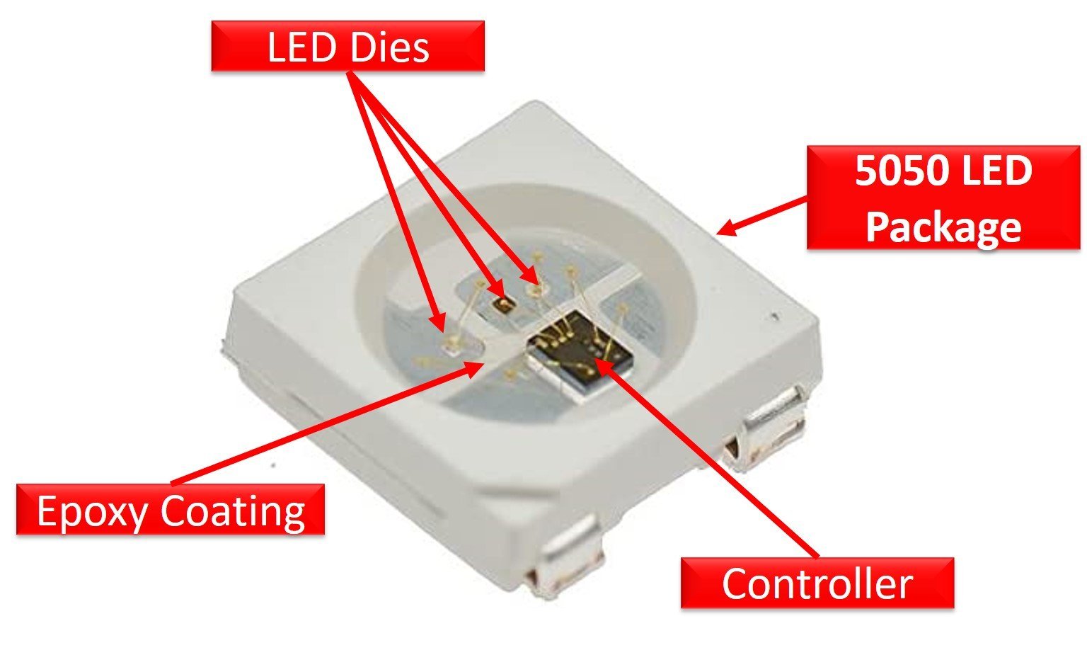
WS2812B RBG LED Internal Components
The following figure shows the internal components of WS2812B RBG LED. It consists of RGB LED dies, a serial programmable controller, and a 5050 LED package.
WS2812B Addressable Serial Controller
The serial controller has a SISO (serial in serial out ) 24-bit register which takes data serially, stores data in the register. Furthermore, based on serial received data, the controller controls the brightness and colors of the RGB LED.

This 24-bit register is divided into 3 parts of 8 bits such as B0-B7, R0-R7, and G0-G7. Each part contains the intensity values of the respective color LED such as blue, red, and green. In this way, a variety of colors are displayed.
How Many Colors can be Displayed?
The question is, how many colors of light we can produce from WS2812B Addressable RGB LED? Well, the simple answer is in millions. Because each part of a 24-bit register is 8-bit long, that means 256 different brightness values are possible for each LED color (green, red, blue). If we combine these 256 options of three colors, we will get around 17 million possible colors,
The IC also has a buffer so that the quality is not compromised despite the large number of LEDs being connected together. This buffer is also used to provide data to LEDs daisy-chained.
How to use WS2812B Addressable RGB LED
WS2812B Addressable RGB LEDs are used in series like LED strips. As discussed earlier, the Din pin receives data serially and Dout pin transmits data serially. Dout pin is used to transmit data received by the first RGB LED to the next WS2812B RGB LED. Similarly, the output of second will go into the input of third WS2812B and so on.

The above circuit diagram shows the connections. All the LEDs have their own ground, power supply, and data pins. VDD which is the power supply pin of all LEDs is connected to a common supply. The same goes for ground pins of LEDs. The input data pin of the first pixel led is connected to the digital pin of the microcontroller or any other source of the signal and receives the data. The output data pin is then connected to the input data pin of the second pixel led and similar connectivity goes on throughout the led strip.
WS2812B Working
The following figure shows the PWM input signal for WS2812B for writing 0, 1 and reset signal to each bit of 24-bit register.
PWM Signal
This addressable RGB LED identifies low, high, and reset logic based on pulse width or duty cycle of PWM signal.
The data transmission in WS2812B works on the principle of pulse width modulation. The below picture depicts the pulse width for 1 and 0.
- Total Pulse-width : 1.25us
- Duty cycle : 36% for 0 and 64% for 1
- Reset pulse-width : >50us

Addressing Each Part of 24-Bit Register
This RGB LED uses a single NZR communication mode. The input data pin receives data from the microcontroller or any other source. The first LED pixel takes the first 24 bit data, passes it to the data latch, and sends the rest of the data to the reshaping and amplification circuit which passes it to the next serial led pixel through the data out pin. After the transmission of the first set of data to all of the led pixels, a reset pulse is sent in order to make all of the led pixels ready to carry out the next set of transmission and so on.
The following figure shows the timing diagram of WS2812B RGB LED. Each WS2812B is addressed in the order shown in the timing diagram. For example, the first 24-bits for the first LED, the second 24-bits for the second LED, the third 24-bits for the third LED, and till the number of LEDs used. After transmission for each data set, we should provide a PWM signal having a pulse width of 50us.

Interfacing with Arduino
After knowing almost everything about these amazing LEDs, we move onto the real project. This section will show an example of interfacing of WS2812B with an Arduino. Make connections of the led strip and Arduino UNO as shown in the figure.

In this circuit, we are powering the LEDs through a 5V Arduino pin but if an external power source is used, one must connect the ground of the Arduino to the ground of the power.
| WS2812B | Arduino UNO |
|---|---|
| GND | GND |
| Din | D5 |
| 5V | +5V |
Arduino Code
We will use FastLED library to control WS2812 LED strip in this tutorial. First download the library and add it your Arduino Library list:
#include <FastLED.h>
#define LED_PIN     6
#define NUM_LEDS    8
CRGB leds[NUM_LEDS];
void setup() {
  FastLED.addLeds<WS2812, LED_PIN, GRB>(leds, NUM_LEDS);
}
void loop() {
  for (int i = 0; i <= 7; i++) {
    leds[i] = CRGB ( 0, 0, 255);
    FastLED.show();
    delay(40);
  }
  for (int i = 7; i >= 0; i--) {
    leds[i] = CRGB ( 255, 0, 0);
    FastLED.show();
    delay(40);
  }
   for (int i = 0; i <= 7; i++) {
    leds[i] = CRGB ( 0, 255, 0);
    FastLED.show();
    delay(40);
  }
}
First, start by including the header file of the “FastLED” Arduino library.
#include <FastLED.h>
Use #define preprocessor directives to defines the number of LEDs and the digital pin of Arduino. Here, we have defined the number of LEDs to 8 and the digital pin 6 of Arduino provides serial data to WS2812B addressable RGB LED.
 #define LED_PIN
 #define NUM_LEDS
CRGB leds[NUM_LEDS];
Inside the setup function, provide digital pin number and number of LEDs to addLEDs structure.
FastLED.addLeds<WS2812, LED_PIN, GRB>(leds, NUM_LEDS);Inside the loop function, we turn on all 8 LEDs one by one with blue, red and green color. This for loop turns on all eight LEDs in blue color from first to the eigth LED with a delay of 40 microseconds.
 for (int i = 0; i <= 7; i++) {
    leds[i] = CRGB ( 0, 0, 255);
    FastLED.show();
    delay(40);
  }
Second, for loop turns on all eight LEDs in red color from first to the eighth LED with a delay of 40 microseconds.
for (int i = 7; i >= 0; i--) {
    leds[i] = CRGB ( 255, 0, 0);
    FastLED.show();
    delay(40);
  }
In the end, last for loop turns on all eight LEDs in green color from first to the eigth LED with a delay of 40 microseconds.
for (int i = 0; i <= 7; i++) {
    leds[i] = CRGB ( 0, 255, 0);
    FastLED.show();
    delay(40);
  }
Code Output
Applications
- Decorations
- Back illuminations
- Tape Light signs
- Recreational purposes
2D Diagram
The following figure shows the 2d model of WS2812B Addressable Led. It shows us the physical dimensions of the components needed when a PCB card is designed.
