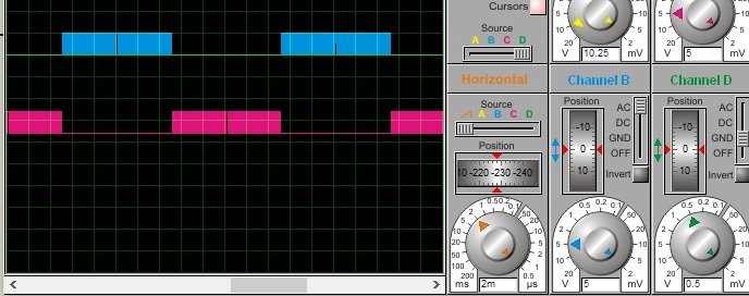
Single phase sine wave inverter using Arduino: I hope all of you are fine and doing well. In today’s project , I am going to talk about our newly design project on arduino based pure sine wave inverter using sinusoidal pulse width modulation technique. I have already written a article on three phase sine wave inverter using arduino. So there are many people who are asking me to make a project on single phase sine wave inverter using Arduino also. I have made a proteus simulation and written a code in Arduino IDE. In this project, I have used Arduino Uno R3 for to generate PWM signals to drive MOSFET driver 1R2110. I will explain it in more detail in later part of this article. This inverter can convert 12 volt DC voltage to 220 volt AC volt with frequency of 50HZ and 60HzZ. User can select either 50Hz or 60 Hz according to their requirement. H bridge topology is used to convert dc voltage into ac voltage. Step up transformer is used to step up output of H bridge to 220V AC. After step up transformer, a LC filter is used to get pure sine wave from pulsating output wave.

Components used in single phase pure sine wave inverter using arduino
Followings are the main components used in single phase pure sine wave inverter using arduino. I provided a brief explanation of each component below:
- Arduino: Arduino Uno R3 is used to generate control signals for MOSFET driver using SPWM ( sinusoidal pulse width modulation technique). For more information on this technique, you can check my article on pure sine wave inverter using pic microcontroller. I have explained each and every thing in this article about SPWM, but that is all about pic microcontroller. Best concept is same so you can apply these concepts to Arduino while writing your code.

- MOSFT driver IR2112 : MOSFT driver IR2112 is used to driver four MOSFET connected in H bridge configuration. It can drive both high side and low side MOSET’s. In H bridge, two MOSFET’s are used in high side configuration and two mosfets are used in low side configuration.
- H bride using MOSFET’s : H bridge is used to convert dc voltage in ac . H bridge operates in two direction, positive direction and negative direction according to PWM gating singals to mosfet. It generate both positive and negative half cycle of AC voltage.
Circuit diagram of single phase pure sine wave inverter using arduino
Circuit diagram of single phase pure sine wave inverter using arduino is given below. I think all the component used in this project are self explanatory or I have explained them above. 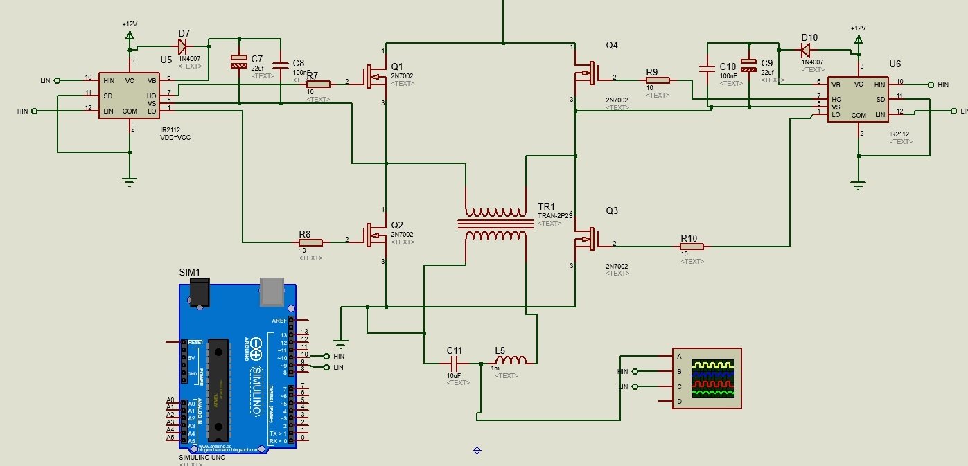
Hello Bilal,
My name is Alex, and one part of my project is to use Arduino and single phase H bridge inverter to get the DC-AC transfer, so could you please show me your arduino code, it is really helpful to me. Thanks a lot.
Kind regards
Hi Alex
code is not free of cost. you can purchase code from here
http://store.microcontrollerslab.com/product/arduino-based-single-phase-sine-wave-inverter-code-and-proteus-simulation/
Dear Sir,
Can I send the details of my project to you, since I want to double check whether I can use that, thanks for your help.
YES send your project details on this email ID : microcontrollerslabhub@gmail.com
Did dead time is added between 2 pulses?
What protection is provided for this circuit?
Nicely written article, I wish it was for free, but I have 3 question.
. Can the pins in the arduino be changed to any other to make the SPWM.
.The 1m inductor ( or inductance) in the output, does it have a core or how do I make the core?
.What guage of wire should i use.
yes it can be changed but it should be PWM pins only and size of wire depends on amount of current
Thank you very much, still don’t understand the output inductance what kind of core do you recommend?
plse sir how do i calculate my lc filter to obtain a sine wave.i have written the code but i having problem with lc filtering calculation
Is it includes the charging circuit and change over ?
you can contact me at microcontrollerslabhub@gmail.com for more details
you can contact me at microcontrollerslabhub@gmail.com for more details
one part of my project is to use Arduino to generate spwm so could you please show me your arduino code and which software you are using for that
please sir, does this arduino code have a PID or any form of feedback control function? im interested in this project
the arduino code of andulor triphase
Please send full project, code and hardware cost.
I really need this code ,please .Thanks you very much !