IR2110 is a high voltage MOSFET driver IC. It can drive both low side and high side switches in half-bridge and low bridge circuits. How to use a MOSFET driver? MOSFET driver circuits are used to drive MOSFETS in a high side or low side. Why we need a MOSFET driver? Because MOSFETs are voltage control devices and used to drive MOSFET the gate capacitance should be charged to operating voltage which is usually between 9-10 volt. One can do it very easily but there is one issue. High voltage on the drain of MOSFET cause problem by interaction with gate-drain capacitance. This problem is known as the miller effect. MOSFET drivers are used to avoiding these issues.
There are many types of MOSFET drivers available in the market. But almost all MOSFET drivers used totem pole output. Because it has low input impedance and high drive current.
- Optocoupler isolated driver circuits
- Transformer isolated driver circuits
- Non- isolated driver circuits
To know about totem pole output and its used a Mosfet driver go through the following article:
NOTE: the current required to drive a MOSFET gate is very low but peak current somehow greater than average current. If peak current required for your application is too high to handle for MOSFET driver IC, you can use external totem-pole output or complementary MOSFET circuits.
Introduction to IR2110 MOSFET DRIVER
In many applications, a floating circuit is required to drive high side MOSFET. In H bridge used in pure sine wave inverter design 2 MOSFET are used as high side MOSFET and 2 MOSFET is used as low side MOSFET. International rectifiers IR2110 MOSFET driver can be used as a high side and low side MOSFET driver. It has a floating circuit to handle to bootstrap operation. IR2210 can withstand voltage up to 500v (offset voltage). Its output pins can provide peak current up to 2 amperes. It can also be used as an IGBT driver. IR2110 floating circuit can drive high side MOSFET up to 500 volts.
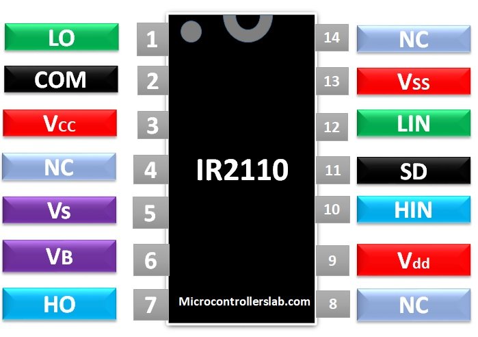
IR2110 Pinout Diagram
This figure represents the pin diagram of IR2210 MOSFET driver IC.
| Pin No. | Pin Name | Description |
|---|---|---|
| 1 | LO | Output pin for a low side gate driver |
| 2 | COM | return path for low side configuration |
| 3 | VCC | power supply pin for low side |
| 5 | VS | floating-point return path for high side drive |
| 6 | VB | floating supply for high side drive |
| 7 | HO | output signal for high side mosfet |
| 9 | VDD | Power supply +5V |
| 10 | HIN | PWM signal input for high side |
| 11 | SD | shutdown pin to turn off system automatically |
| 12 | LIN | PWM signal input for low side |
| 13 | VSS | Power supply ground |
For electrical features and specification download IR2110 DataSheet:
How IR2110 work?
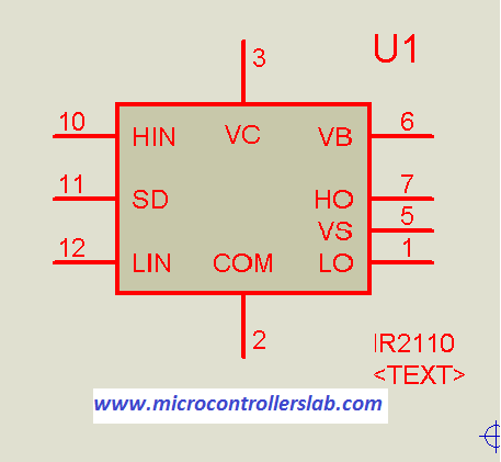
The pin configuration and functionality of each pin are given below:
- Pin 1 is the output of low side MOSFET drive
- pin2 is a return path for the low side. It is at the same potential as ground VSS pin 13. Because when an input to the low side at pin 12 Lin is high, LO output will be equal to the value of Vcc voltage at pin 3 with respect to Vss and COM pin. When hen input to low side at pin 12 Lin is low, LO output will be equal to the value of VSS and it means zero.
- VDD pin 9 is a logical supply pin. Its value should be between 5 volts. But if you used voltage less than 4 volts it may not give you the required result.
- HIN pin 10 is an input signal for high side MOSFET driver output. It may be from a microcontroller or any other device. But input signal logic level should be between 4-5 volt.
- LIN pin 12 is an input signal for low side Mosfet driver output. It may be from a microcontroller or any other device. But input signal logic level should also be between 4-5 volt.
- SD pin 11 is used as a shutdown pin. you can use it for the protection circuit. For example in over voltage or over current protection circuit, if any of these values become greater than specified values, you can give a 5-volt signal to shutdown IR2210 driver to stop driving MOSFETS. In return, your circuit will stop working.
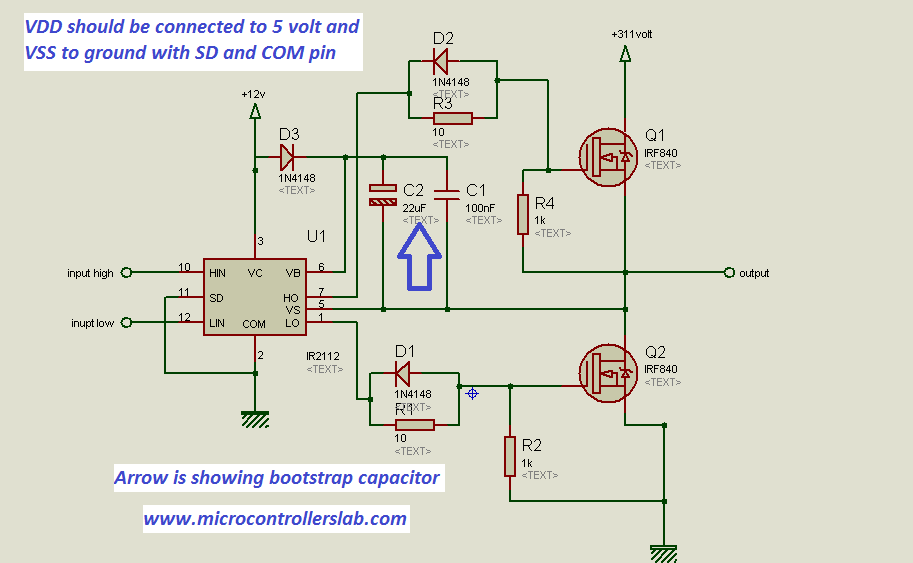
- VB pin 6 is used as a high side floating supply of floating circuit to provide floating voltage to high side MOSFET.
- The bootstrap capacitor used between VB and VS to fully operate high side MOSFET. It plays a very important rule in H bridge of pure sine wave inverter. you should use bootstrap capacitor value 22uf-40uf. I have successfully designed H bridge after making many changes in H bridge with 33uf/50v bootstrap capacitor value.
- For more detail I recommend you to go through datasheet of IR2210 and one tip for those readers who are from Pakistan, Don’t purchase IR2110 from Pakistan. Because low-quality IR2110 IC’s are available in Pakistan which burns again and again and will make you hopeless. I have already gone through this situation while working on my final year project “Hybrid pure sine wave inverter”.Then I used IR2112 and it works perfectly. Because IR2212 and I2110 both are almost the same and their pinout is the same. I recommend you to use IR2112 also in your project.
Electrical Features
- It can provide Gate voltage between 10-20 volts.
- For the high side of the H-Bridge circuit, the bootstrap operation operating range is +500V or +600V.
- Compatible with CMOS and TTL logic
- Protection for Under-voltage for LO and HO pins/channels
- Automatic shutdown with a feedback circuit
- Synchronized propagation delay
- Output voltage: 10-20V
- Output Current: 2A
- Switching time: on time=120ns and off time=94ns
IR2110 as low side or high side MOSFET DRIVER
high side and low side MOSFET driver in half-bridge
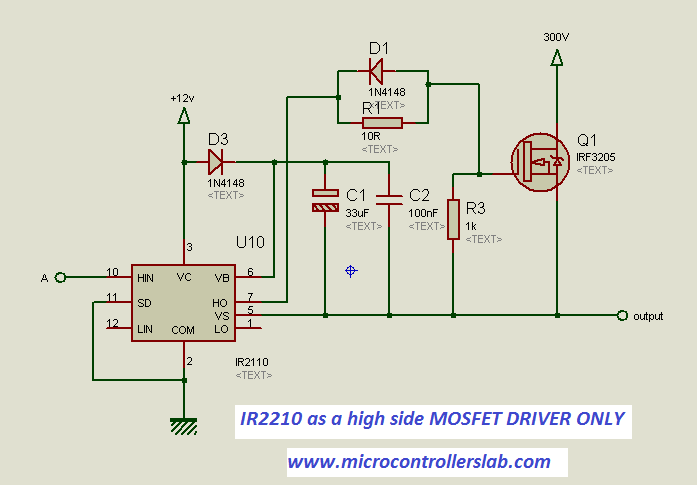
IR2110 as a high side MOSFET driver
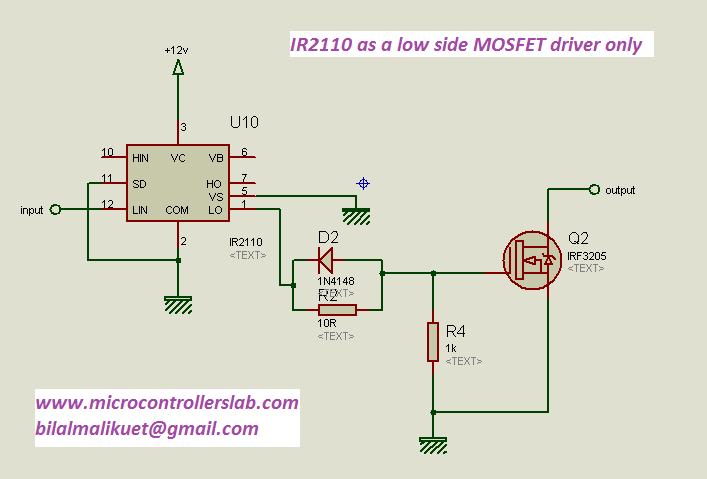
IR2110 as a low side MOSFET driver
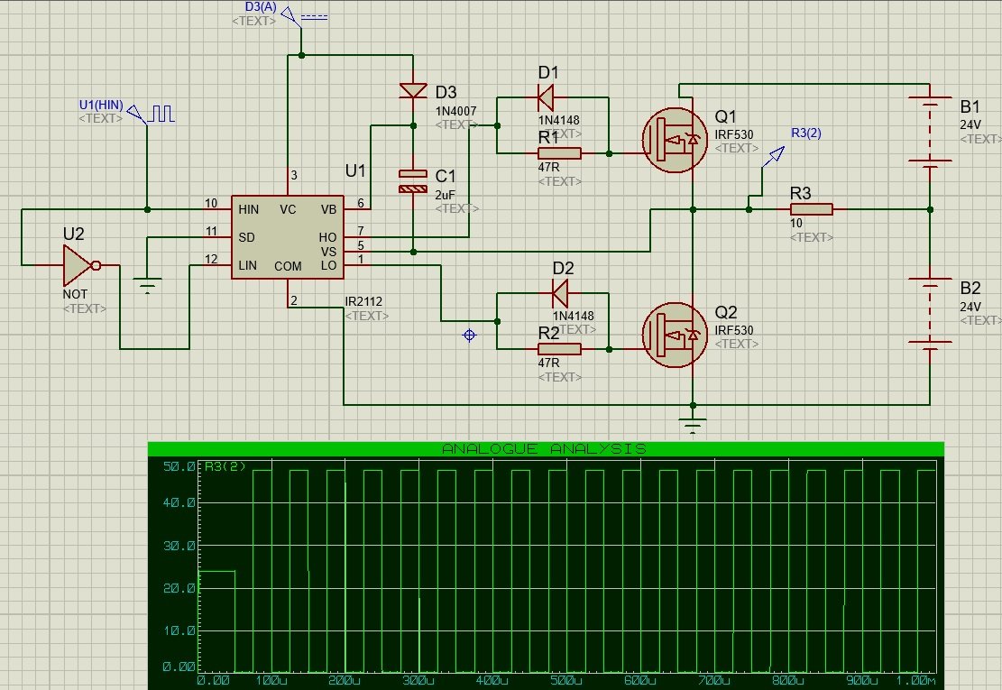
IR2110 Example Half-Bridge inverter
In this example, the half-bridge inverter circuit is designed using Mosfer driver and IRF530 Mosfets. Single IC drives both high side and low side Mosfets. Mosfets are used in half-bridge configuration mode. 50Hz PWM signal provides input to HIN and LIN pins. Not Gate provides an inverted signal to pin 12 that is input signal for low side Mosfet.
2D Dimension diagram
You always require an exact physical dimension while designing a PCB. This picture depicts the 2D dimension diagram of IC.

Applications
- DC motor driver
- AC Motor Speed control
- Half, full and three-phase bridge
- Pure sine wave inverter
- Soft starter for three-phase induction motor
could you send me a simple simulation of ir2110 on multisim. my email address shahnawaz2103@gmail.com.
thanks if you help me.
I am having same problem. I could not find IR2110 Model in Proteus. Pleas upload the IR2110 for new newbie learner. my email id is info.bkar@gmail.com
Regards,
Bahadur Kar
IR222 is available in proteus. It have same features of IR220, you can use it for simulation purpose
can it be used to make esc for 3 phase bldc?
very good
please could you send me the schematic? I did the same scheme in my proteus and put the output as a motor, but it does not work, the engine did not turn when I put the entries in Hin and Lin
My email: felipenele@hotmail.com
I need to know the PWM control of H bridge inverter in proteus ( if possible using atmega328). If i get a mail of the model i will be happy. Else i need the above model .How to use IR2110 drive for MOSFET.
HELOOO SIR… IN THE ABOVE CIRCUITS U DIDNOT MENTIONED ABOUT VDD…IS THERE IS NO NEED TO GIVE INPUT TO VDD FOR IR2110 TO WORK AS HIGH SIDE OR LOW MOSFET DRIVER….PLSS HELP ME SIR….THANK U
Vdd= 5 volt and it is default connection in proteus.
IR2110 PROTEUS LİBRARY MODULE ,SEND ME PLEAS .
mirabbas92@gmail.com
First of all thank you very much sir for these articles they have been of immense help.Also can u please send me the IR2110 PROTEUS library module as i didnt find it in the components library.
my email id is soumitragoswami.eee48@gmail.com
hi bilal ,
I want to know about high side driver and low side with simple basic circuit using MOSFET.
Can you please provide me detailed explanation .
What is the control voltage on VH, VL?
how to change the pulse width?
generate a pwm with any microntroller with variable duty cycle
Project buck converter with Vin = 20V mine, Vout = 14.4V, Iout = 12A for charging batteries, you can use the type IR2112 is not? ic IR21xx use is justified?
Hi Bilal Malik
Hi Bilal Malik.
Can you help me something?
Hi
i want to use n-channel mosfet as switch in high side , i want to be “on” for long time or “off” for long time, (manual switch , not pulsed)
if i give in 5+ the mosfet on and if 0 mosfet off
can i use it ?
Hi Mr. Bilal Malik. I want to design a micro controller based single phase H-bridge inverter. The whole circuit is made of PIC 16F877A, two IR2110 MOSFET driver, four IRF840 power MOSFETs plus the snubber circuits. I want to get pure 220V (Vrms) and 50HZ sinusoidal signal from an H-bridge after it is filtered. I write two 50HZ square wave (one for Low side and one for High side), which are 180 degree out of phase (Logic inputs to the H-bridge) to the first half of the H-bride and two PWM signal (5KHZ which are square wave), (one for Low side and one for High side), not simultaneously ON for both sides to the next half of the H-bridge using MikroC code. But I can’t get pure sinusoidal signal. What shall I do?
I Don’t get step up transformer in Proteus , then
How you step up the output of H -bridge
y tryng the half bridge to 16f877a and ir2110 ,but y dont say how to make this,how to use two pwm and dead time
hi!
could you email to me this modelling. Im really appreciate your help.
email: maamansor1@sheffield.ac.uk
Hi bilal could you please send me this schematic ? my mail is muhammadali4035@gmail.com
I had done schematic for driving high side voltage but as i vary for HIN 0v or 5v two get the same result so i want to know the schematic for real circuit with load
Hi Bilal, i have one problem at HO pin the amplitude of my output is continuously decreasing what should i do for that.
Hi,
Nice explanation.Thanks for that.
Hi ,i need pure sine wave inverter circult for 1kva.
contact me at microcontrollerslabhub@gmail.com if you need my project service
hello I am from Nepal. I am also working on a project of 3 phase inverter and required this IC. I wanted to know , how did you select the value of the capacitors to be used here ?
check data sheet of IR2110
Omce I msde the 3 phase in putpowet supply
I chose the 10 micro farads 400 volts of cours
It is elevtroletic set ofter diods
Helloooo sir … i need the above model .How to use IR2110 drive for MOSFET.
Qusayali30@yahoo.com
Could you please tell me why pin HO is always 12v although no PWM in pin HIN ( i measured by volt metter) . I have tried IR2110 & IR2112 but it has the same result. Thanks in advance!
Me too having same problem. Why is HO pin always High?
Hello sir , I am shameed pasha from India, I am using pmdc motor drive , using 1R2110. But MOSFET burn regularly, please suggest me what we can do. My mail I’d shamid27@gmail.com
Thank you
Hello… I am from UET taxila and I need your help. It is my semester project and I want Simulation on any software. Please waiting for your kind concern. Thanks Here is my email ID. (aliahmad78016@yahoo.com)
Hi!! I was seeing the IR2110 AS LOW SIDE OR HIGH SIDE MOSFET DRIVER circuit, and I didn’t understand one point: “The picture is saing that VDD should be conected to 5 Volts and VSS to ground…”
How can I do this if this terminal (VDD) is not present in the component?? Thanks
hello can you help me in my project cascade h bridge mli
Hello i have a problem with the abve circuit because i try to drive my mosfet with an irf2112 mosfet driver as high side but proteus found it difficult to simulate meanwhile using the a pulse signal my buc converter functions very well.
Please help me. i need it for my final year project
Hi Bilal
I have facing problem when i connected rectified DC Voltage to MOSFET Drain.
Why it is happened please guide me . I am in great trouble.
Thanks
vary useful subjuct thanks for your work
Hi Bilal, In the above circuit why have you grounded the SD pins while your notes say that it is a shut down pin which would work when you give it a 5v signal.
Hi Bilal. I need the pcb circuit of this design. PLease can you send me it?
kemalkorkmaz23@hotmail.com
Hi mr. Bilal
Thanks for your datas.
I have a problem in my circuit.
I am running a half bridge inverter using IC IR2103 and MOSFET IRF840.
when IC is feeded by 12 volt, the output voltage of VB is nearly 11.7 and the output voltage of VS is nearly 10.3.
but the value of VS is not logical, why is this problem is happening?
i wanna ir2110 proteus module plz .. i really need it plz plz plzzzz
Hi, i’m BOY
i wanna ir2110 proteus module plz…chaiwat5204@gmail.com
thank you
Hi, i’m BOY
i wanna ir2110 proteus module
chaiwat5204@gmail.com
thank you
Can you connect the output load ground to the same ground as the COM pin? If not how do you connect the ground of the load (attempting to do a buck converter)
Hi, i am using ir2110 mosfet driver and IRFZ44N mosfet. I am working in stepper Driver project. But stepper drive not roation. Please give me help
I AM HAVING A PROBLEM USING IRF9540 AS YOU KNOW EVERY TRANSISTOR HAVE Vgs= +_18V MY SOURCE VOLTAGES ARE 80V AND WHEN I DRIVE THE GATE USING PWM SIGNAL IT DOESTNT WORK PROPERLY CAN ANYONE HELP ME IT
hii..im designing a buck-boost converter for solar system .i/p rages from 40v to 150V and o/p required is 48v 7A.i dont know how to use mosfet driver properly as i read above article i tried but its not working …pls help me
hello. i have one question!! how to calculate bootstrap capacitor and what’s the value of the bootstrap rsistor to fully charge the capacitor and what kind of diode we can use?
Can someone send me this simulation file? please its urgent
aamir.1919@outlook.com
Hello, i’m doing a H bridge with a FAN 7382. It is a high-low si de driver. My problem is that I hace always the Hout in HIGH and my LOUT is always LOW. I am using a PWM but it does not change the state of the outputs. Could you please help me? Thanks in advance.
Good evening my friend could pass this component
For me I’m studying ir2110, I would like to simulate it in proteus
assistenciatabira@hotmail.com
hi sir.i want to derive mosfets with ir2110 or ir2113.but i dont find this to libraries of proteus 8.even i add some libraries to program but dont usefull…could U helo me please
Hi,
I case of voltage higher than 900Vdc , what IC driver and how to use it.
Thanks you very much
Sorry ???? my mistake. It works like a charm.
Great
IR2110 PROTEUS LİBRARY MODULE ,SEND ME PLEASE
IR2110 PROTEUS LİBRARY MODULE ,SEND ME PLEASE
montassar.belarbia@gmail.com
how to select capacitor value for driving 600V 25 A USING IR 2110 .plz mail at moreysuryakant@gmail.com
hi , bilal
how i can connect optocoupler with ir 2101
i need this circuit with microcontroller.
sir if you have proteus simulation of IR2110 as high side and low side mosfet driver in half bridge circuit mail on this id waseemarshad9968@gmail.com
Hi Bilal,
Can I use IR2110 as a High side Mosfet driver (only) for a buck DC-DC converter in a stand-alone PV system?
Tnx for sharing your experience.
I want use IR2110 in 20MHz. What do you think?
Is it possible or not?
Any one have IR2110 library. Please can any one send me it will be a grate help
This is my email,
rishiedni@gmail.com
hello
how are you??
i wanna make a H bridge circuit in proteus but i cant find IR2110 component in Proteus library .also i tried to find it on internet but i couldnt.
can you send me the library for proteus??
vghasemi68@yahoo.com
thanks
hello
sir if you have proteus simulation of IR2110 as high side and low side mosfet driver in half bridge circuit mail on this id vghasemi68@gmail.com
thanks
hi
can i have this simulation please?
thanks
ehsan202013@gmail.com
Hello there.
In case of some special inverters that the lower switch gate signal is not opposite of higher switch gate signal, can it still be used like the first picture of schematic?
Good day sir. I really need your advice. My solar charge controller is not charging. After checking the circuit I found out that there is not voltage coming from the(IR2110) HO to the gate of the mosfet. But there is signal coming to HIN. What do you think is the problem. Could it be that the mosfet driver is bad?
How abou Vdd is more than 5v? Is there any effect on ir2110?
brother, thank you very much for the great information
God bless you
but my question is this! how will I connect the two output of sg3535 to ir2110 on full bridge inverter?
Why am asking this question is because the ir2110 is two each having two input signal each which is Hin and Lin, so in this situation how is going to be the connections?
pls help me
hi
could you email to me this modeling? I really appreciate your help.
p.mansournia@gmail.com
Hi Bilal,
can we use a p-channel mosfet on the highside ? and how ?
And how do we get the negative supply to control the p-channel mosfet ?
thanks
Hi, I’m sazwan
Does anyone have an IR2110 library for proteus software? Please can anyone send me it will be a great help
Please check the latest version of the proteus. It has a library of IR2110
Please I build a hbridge inverter using ir2110 as a my mosfet driver and sg3525 as my source but I noticed that if I connect the sg3525 with the ir2110 the sg3525 heat up but if I disconnect the ir2110 from the sg3525 it will not heat up what could be wrough
dear BIlal,
can we connect SG3524 output with IR2110 and obtain pure sine wave with H bridge.
if there any schematic please help me.
CAN YOU SEND ME PLEASE IR2110 PROTEUS LİBRARY MODULE?
can you please send the file to this email: raihanmg38@gmail.com
I try putting the same component as you do on the video but it doesn”t work as it seems. I really appreciate it if you can help me
hello, I would like to know if the input signal to IR 2112 must be a PWM signal or it can just be a continuous pulse, since I do the assembly but when sending a continuous signal the motor runs but does not stop. Thanks
Hi, I’m sazwan
Does anyone have an IR2110 library for proteus software? Please can anyone send me it will be a great help