The photoresistor module is also known as the light-dependent resistor or LDR. This device is useful in detecting the presence, absence, or intensity of light. It has a light-sensitive resistor whose resistance varies based on the light received by the LDR Module. In the darkness, the resistance of LDR is high, around 1 M ohm, whereas when LDR is placed under a light, its resistance drops significantly, down to a few ohms. This change in resistance allows the LDR module to sense and respond to varying light levels.

Recommended Components
The following components are used in this project or are helpful for building it with the Arduino.
| Component | How it’s used in this project | Buy on Amazon |
|---|---|---|
| Arduino Uno R3 | The main board that runs the sketch and controls all the components in this project. | Check Price |
| LDR / photoresistor | Light-dependent resistor whose changing resistance lets the Arduino measure ambient light intensity. | Check Price |
| Breadboard | A solderless breadboard for prototyping and wiring the circuit without soldering. | Check Price |
| Jumper Wires | Male-to-male jumper wires to connect the Arduino to the breadboard and modules. | Check Price |
As an Amazon Associate we earn from qualifying purchases. Prices and availability are accurate as of the date/time indicated and are subject to change.
Photoresistor Introduction
A photoresistor, also known as a light-dependent resistor (LDR) or photocell, is a type of passive electronic component that changes its resistance based on the intensity of light falling on its surface. It belongs to the family of resistors, but unlike regular resistors, its resistance varies with the amount of light it receives. The photoresistor is sensitive to light in the visible and near-infrared spectrum and is commonly used in light sensing applications.
How LDR Works?
The basic construction of a photoresistor consists of a semiconductor material with high resistance in the dark and lower resistance when illuminated. When light hits the photoresistor, the photons excite the electrons in the semiconductor material, causing them to move and reducing the resistance. Conversely, in the absence of light, the resistance of the photoresistor increases.
The sensitivity of a photoresistor can be tailored by using different semiconductor materials and controlling the physical dimensions. Photoresistors are available in various shapes and sizes, making them versatile for use in different electronic circuits and light-sensitive applications.
When the intensity of light falling on the LDR is higher, its resistance will be lower, and when the intensity of light falling on the LDR is lower, its resistance will be higher. The module also has a 10K pull-down resistor. This module is useful in many projects where we need to automate the light based on the light intensity. The applications of LDR are in cameras, street lights, detectors, and light control devices.
Photoresistor Module Applications
The LDR’s sensitivity changes with the wavelength of light coming at it, and they are non-linear devices. Applications of photoresistors include light sensors in streetlights, automatic outdoor lighting systems, camera exposure control, darkness detection in electronic devices, and light-dependent switches. Their simplicity, low cost, and ease of use make them popular components in various electronic projects and consumer products where light sensing is required.
We have done some microcontroller-based projects using LDR, you may refer to them:
YouTube Video:
Specifications of Photoresistor Module
The photoresistor (KY-018) module has the following specifications:
- This module operates on 5V DC.
- It is compatible with any microcontroller
- It is sensitive to temperature.
- This LDR module provides an analog output.
Types of Photoresistors
According to the features, the photoresistors are of three types:
- Ultraviolet photosensitive resistors
- Infrared light-sensitive resistors
- Visible photosensitive resistors.
Features of Photoresistors Module (LDR)
The main features of the photoresistors are as follows.
| Phenomenon | Affects on LDR |
| Dark Current | In cases of darkness or very low light, some of the current still flows through the LDR; this is called as dark current. |
| Dark Resistance | The ratio of applied voltage across LDR and the current flowing through it is known as dark resistance. |
| Sensitivity | The LDR is light-sensitive. When light falls on it, its resistance decreases, and in darkness, its resistance increases. |
| Volt-Ampere Characteristic Curve | When the light intensity is low, it represents the bottom part of the volt-ampere characteristic curve, where current is low for an applied voltage. However, when the light intensity is high, it represents the upper part of the volt-ampere characteristic curve where the current is high for an applied voltage. |
| Temperature Co-efficient | The LDR modules are temperature-sensitive. When the temperature is low, the sensitivity will be high, and at a high temperature, the sensitivity will be low. |
| Rated Power | When the temperature is higher, the power consumed will be reduced. |
Pinout of Photoresistor Module
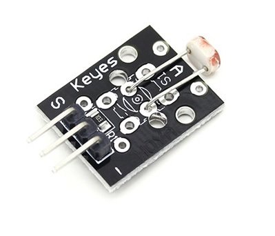
The photoresistor module has three pins. These pins from left to right are
- S: Output pin
- +5v: Input voltage pin
- GND: Ground
PhotoResistor Interfacing with Arduino
The connection scheme is very easy. You just have to connect three pins. Connect the 5V and ground of the module with the 5V and ground of the Arduino. Then connect the signal pin of the module with the A0 of the Arduino.
| Arduino Pin | Photoresistor Module Pin |
|---|---|
| A0 | S or signal |
| 5V | + or VCC |
| GND | – or GND |
The Arduino board will give us an analog value between 0 and 1023 on the A0 pin. When there is no light, the analog value will be lower, and when the intensity of light is higher, the analog value will be higher. We have set a threshold value in the code, which is 500. So, when the value is lower than 500, then the Arduino will turn on pin 13, where it has a built-in LED that will glow up. You can also connect a LED to any other pin you want.
Hardware Components
Here we have listed the hardware components we will be using in this tutorial:
- Arduino board
- Photoresistor Module
- Jumper Wires
Schematic Diagram
In this section, we have provided the schematic diagram. This schematic diagram helps us properly connect our Arduino Board to the KY-018 LDR module.

The wiring schematic is very simple. We have connected the GND pin of the KY-018 LDR Module to the GND pin of our Arduino Board. Then we connected the middle pin to 5V, and at last we connected the S pin to pin A0 of our Arduino Board. These connections can be seen in the schematic above.
Arduino Sketch PhotoResistor – Light Measurement using LDR
Open the Arduino IDE and go to File > New to create a new file. Now copy this sketch given below and paste it in the Arduino File. Select the COM port of the connected Arduino board and click Upload. This will upload the sketch to the Arduino board. If you have followed the tutorial correctly, the Arduino LED should turn ON when LDR is exposed to light and turn OFF when placed in darkness.
// This code is for the Photo resistor Module.

int sensorPin = A0 ;                      // Selecting A0 as the sensor input pin.

int ledPin = 13 ;                          // Selecting pin 13 as the LED pin

int sensorValue = 0 ;    // variable to store the value coming from the sensor

void setup ( ) {          // code written in it will only run once.

  pinMode ( ledPin , OUTPUT ) ;    // Declaring pin 13 as output pin

  Serial.begin ( 9600 ) ;     // Setting baud rate at 9600

}

void loop ( )  {       // Code written in it will run repeatedly

  sensorValue = analogRead ( sensorPin ) ;   // Reading data from pin A0 and storing in Sensor value

if ( sensorValue < 500)

{

digitalWrite ( ledPin , HIGH ) ;     // This will set the pin 13 as high

Serial.println ( " The value of LDR is = " ) ;   // This will print " The value of LDR is = " on display

Serial.println (sensorValue ) ;    // This will print the value of LDR on display

delay ( 1000 ) ;     // This will give delay on 1 sec

}

else

{

  digitalWrite ( ledPin , LOW ) ;      // This will set the pin 13 as low

Serial.println ( " The value of LDR is = " ) ;

Serial.println ( sensorValue ) ;     // This will print the sensor value on display

delay ( 1000 ) ;     // This will give delay of 1 sec

}

}
Code Explanation
In this section, we will discuss the workings of this code in more detail.
int sensorPin = A0 ;      // Selecting A0 as the sensor input pin.

int ledPin = 13 ;             // Selecting pin 13 as the LED pin.

int sensorValue = 0 ;   // variable to store the value coming from the sensor.
In this section, we have assigned the sensor input pin as A0 and the led pin to 13 to turn the LED On or Off using Arduino. The sensorValue is initially set to 0.
void setup ( ) {                 // code written in it will only run once.

  pinMode ( ledPin , OUTPUT ) ;    // Declaring pin 13 as output pin

  Serial.begin ( 9600 ) ;       // Setting baud rate at 9600

}
In the void setup() function, we have initialized the pin mode of led pin (11) to OUTPUT and started the Serial monitor at a baud rate of 9600 using the Serial.begin() function.
void loop ( )  {          // Code written in it will run repeatedly

sensorValue = analogRead ( sensorPin ) ;  // Reading data from pin A0 and storing in Sensor value
In the void loop() function, we will read the analog pin A0, denoted as the sensor pin, and store it in the sensorValue variable.
if ( sensorValue < 500)

{

digitalWrite ( ledPin , HIGH ) ;     // This will set the pin 13 as high

Serial.println ( " The value of LDR is = " ) ;    // This will print " The value of LDR is = " on display

Serial.println (sensorValue ) ;      // This will print the value of LDR on display

delay ( 1000 ) ;           // This will give delay on 1 sec

}
Now using an if condition, we will set a condition that if sensorValue is less than 500, the LED will turn on, and the serial monitor will print the line “The value of LDR is = sensorValue” with a delay of 1 ms.
else

{

 digitalWrite ( ledPin , LOW ) ;        // This will set the pin 13 as low

Serial.println ( " The value of LDR is = " ) ;

Serial.println ( sensorValue ) ;     // This will print the sensor value on display

delay ( 1000 ) ;          // This will give delay of 1 sec

}

}
In the else section, the LED will turn Off using the digitalWrite function. The serial monitor will print the line “The value of LDR is = sensorValue” with a delay of 1 ms.
Conclusion
Here we have summarized the things we have learned in this article:
- What is a photoresistor?
- Applications and types of LDR.
- Features and Pinout of LDR module.
- Arduino Schematic and Example Sketch.
This module has a wide range of applications. It is useful in many projects where lighting automation is necessary. You can also check out electronics projects based on LDR for automatic street light control and auto intensity control of street lights.
Related Article:
- BH1750 Ambient Light Sensor Interfacing with Arduino
- Arduino with BMP180 Atmospheric Pressure and Temperature sensor
- Arduino LED Slider Brightness Control Android App with MIT App Inventor
- I2C Communication Between Two Arduino Boards
- RC522 RFID Reader Module with Arduino
- MAX30102 Pulse Oximeter and Heart Rate Sensor with Arduino