In this tutorial, we will learn how to build an android app with a slider that will enable us to control the brightness of an LED connected with Arduino. The slider will be moved to set the slider value. In response, this slider value will set the duty cycle of the PWM signal generated by Arduino. In short, this variable duty cycle PWM will control the LED brightness. This android app will be created with MIT App Inventor. The transmission of the data will be through the HC-05 Bluetooth module.
Recommended Components
The following components are used in this project or are helpful for building it with the Arduino.
| Component | How it’s used in this project | Buy on Amazon |
|---|---|---|
| Arduino Uno R3 | The main controller board that receives the slider value over Bluetooth and sets the LED brightness via PWM. | Check Price |
| Breadboard | Solderless board to build the LED circuit and mount the Bluetooth module. | Check Price |
| Jumper Wires | Used to wire the LED, resistor, and HC-05 module to the Arduino. | Check Price |
| 5mm LED | The output LED whose brightness is controlled from the Android app slider. | Check Price |
| Resistor Kit (220/4.7k) | Provides the current-limiting resistor in series with the LED. | Check Price |
| HC-05 Bluetooth Module | Receives the brightness value sent from the MIT App Inventor Android app. | Check Price |
As an Amazon Associate we earn from qualifying purchases. Prices and availability are accurate as of the date/time indicated and are subject to change.
LED Brightness Control Slider Android App Project Overview
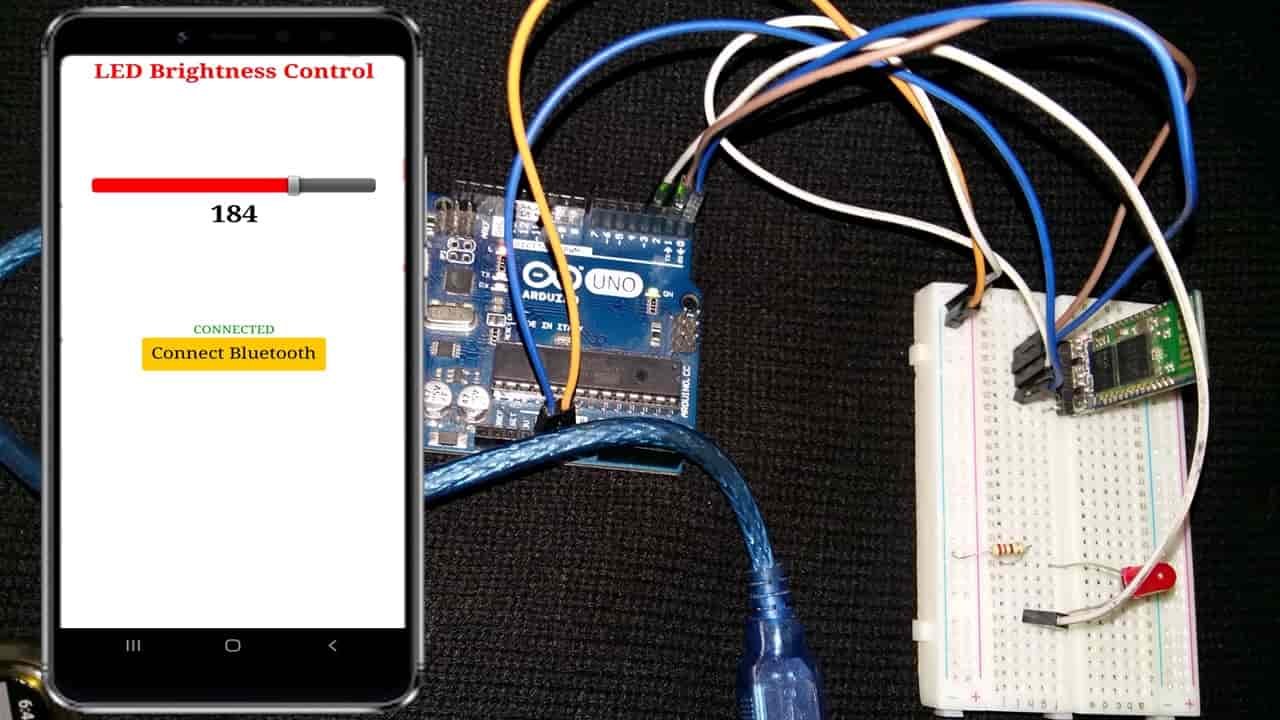
We will create an Arduino IoT app through HC-05 and MIT App Inventor to control the brightness of an LED connected with Arduino. The android app features a slider which allows the user to set the brightness of the LED. The user will move the slider to set the duty cycle. The slider value will update to a new one as we move the slider. The slider will have a maximum value of 255 (duty cycle of 100%) and minimum value of 0 (no PWM) as we will be using 8-bit resolution. When Arduino receives the slider value, it alters the PWM cycle by setting the duty cycle according to the value. Thus the slider will be used to control the brightness of the LED where the increasing values increase the brightness.
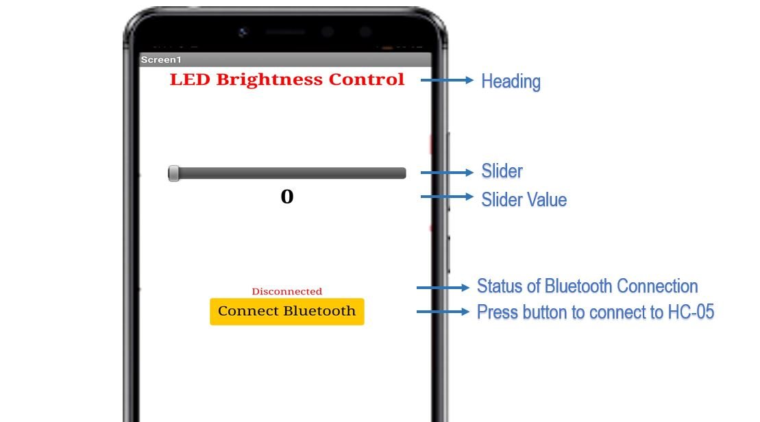
To enable Bluetooth connectivity, there is a button saying ‘Connect Bluetooth’ that opens a List picker which opens up Bluetooth devices currently paired with the android phone. You can select HC-05 Bluetooth module from the list. Another label saying Bluetooth is Connected or disconnected is also shown on the screen.
We will require the following for our project:
Hardware Required:
- Arduino UNO
- LED
- 220 ohm current limiting resistor
- HC-05 Module
- Connecting Wires
- Breadboard
Software Required:
- Arduino IDE
- MIT App Inventor
- Android Smartphone with MIT AI2 Companion installed
PWM Introduction
PWM stands for Pulse Width Modulation. From its name, it is clear that in this technique the width of pulses of a waveform is controllable (changes). This means for how much time a pulse is in the HIGH state or in the LOW state from a given time is controllable.
In this technique, we use digital means to get an analog result. Digital control is used to create a square waveform by switching a signal ON and OFF repeatedly. This ON and OFF pattern generate full VCC voltage at the ON position and 0V at the OFF position.
The duty cycle is defined as the average ON time of a pulse divided by the TOTAL time of the pulse, so basically in PWM, the duty cycle of pulses is changed.
For more information on PWM pins of Arduino, read this in-depth article:
What is Pulse Width Modulation
Arduino PWM Pins
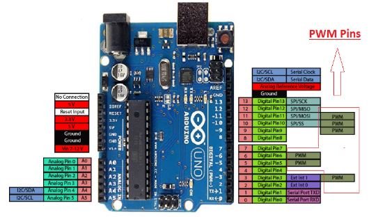
There are 6 PWM pins available on the Arduino UNO board and the Pins number are 3, 5, 6, 9, 10, 11. The number of PWM pins vary from one Arduino board to another Arduino Board. The following table shows the PWM pins for Arduino Uno, Arduino Mini, Arduino Nano, and Arduino Mega. It also lists the default PWM frequency of each pin.
| Board | Pins | Freqeuncy |
|---|---|---|
| Arduino_Uno | 3, 5, 6, 9, 10, 11 | 490 Hz (pins 5 and 6: 980 Hz) |
| Arduino_Nano | 3, 5, 6, 9, 10, 11 | 490 Hz (pins 5 and 6: 980 Hz) |
| Arduino_Mini | 3, 5, 6, 9, 10, 11 | 490 Hz (pins 5 and 6: 980 Hz) |
| Arduino Mega | 2 to 13, 44 to 46 | 490 Hz (pins 3 and 11: 980 Hz) |
In this tutorial, we will use the Arduino Uno. But the overall concepts to generate PWM remains valid for other Arduino boards also.
The following figure shows these pins on Arduino UNO Board.
Arduino AnalogWrite() PWM Function
The analogWrite() function which is available by default in Arduino IDE is used to generate a PWM signal. The function can generate PWM with the default frequency of each pin as mentioned in the above table. At each of these pins, a PWM waveform of fix frequency can be generated using the analogWrite() command.
The first argument to analogWrite() is a pin number from which we want to get PWM signal. The second argument is a duty cycle. The duty cycle can vary between 0 to 255 which maps to 0 to 100% duty cycle in percentage.
By default, the waveform of the following frequency is generated by Arduino pins when called using the analogWrite() command.
- The frequency at Pin 5 and Pin 6 is 980Hz.
- The frequency at pin9, pin10, pin11, and pin3 is 490Hz.
Interfacing LED and HC-05 module with Arduino board

We have mentioned the Arduino UNO pins where PWM is supported. So choose a PWM pin to connect with the anode pin of the LED. We have used digital pin 3 as the PWM pin. In the below schematic, we can see that Pin3 is connected with the anode pin of LED, and the cathode pin is connected with the common ground through the 220-ohm resistor.
To connect HC-05 module with Arduino, follow the connections below:
- Bluetooth Tx with Arduino UNO Rx (D0)
- Bluetooth Rx with Arduino UNO Tx (D1)
- Bluetooth VCC with Arduino UNO +5V
- Bluetooth GND with Arduino UNO GND
The schematic diagram below shows the connection between LED, HC-05 and Arduino UNO.

NOTE: Make sure you plug out the Tx and Rx pins out of Arduino before uploading the program. After uploading the program connect them back. Otherwise, you can get an error.
You may also like to read:
Arduino Sketch LED Brightness Control Slider
Open your Arduino IDE and go to File > New to open a new file. Copy the code given below in that file.
int ledPin = 3;
int pwmValue;
int flag = 0;

void setup() {
  Serial.begin(9600);
  pinMode(ledPin, OUTPUT);
  analogWrite(ledPin, LOW);
}
void loop() {
  if (Serial.available() > 0) {
    pwmValue = Serial.read();
    flag = 0;
  }
  if (flag == 0) {
    analogWrite(ledPin, pwmValue);
    flag = 1;
  }
}
How does the Code Works?
Firstly, we will define the Arduino PWM pin that we will connect with the LED. It is pin3 in our case. You can use any appropriate PWM pin.
int ledPin = 3;Next, define two int varaibles. The ‘pwmValue’ will hold the slider value set by the user. The ‘flag’ will be used to check that the serial prints the pwmValue once.
int pwmValue;
int flag = 0;
Inside the setup() function, we will open the serial communication at a baud rate of 9600. Also, configure the ledPin as an output pin and set its state to LOW so that initially it is OFF.
void setup() {
  Serial.begin(9600);
  pinMode(ledPin, OUTPUT);
  analogWrite(ledPin, LOW);
}
Inside the loop() function, we will first check if data is available in the serial port. If data is available then store it in the variable ‘pwmValue’ and set ‘flag’ to 0. Now if flag is 0 then change the brightness of the LED using analogWrite() function and set ‘flag’ to 1. The anlogWrite() function will take in the ledpin and the pwmValue as the parameters inside it. Note that the ‘pwmValue’ will consist of values between 0-255 which the user will set by moving the slider on the android app.
void loop() {
  if (Serial.available() > 0) {
    pwmValue = Serial.read();
    flag = 0;
  }
  if (flag == 0) {
    analogWrite(ledPin, pwmValue);
    flag = 1;
  }
}
Building App with MIT APP Inventor
MIT App Inventor is an incredible web application that helps users build interesting Android applications. It is a block-based programming tool through which users can create fully functional apps for Android devices such as smartphones, tablets e.tc. Often termed beginner-friendly, even people with no prior experience in programming can easily learn how to use this application efficiently. We will use this tool to build our Arduino app as well.
Steps to Create Android App
Go to the following website: and click the ‘Create Apps!’ button.

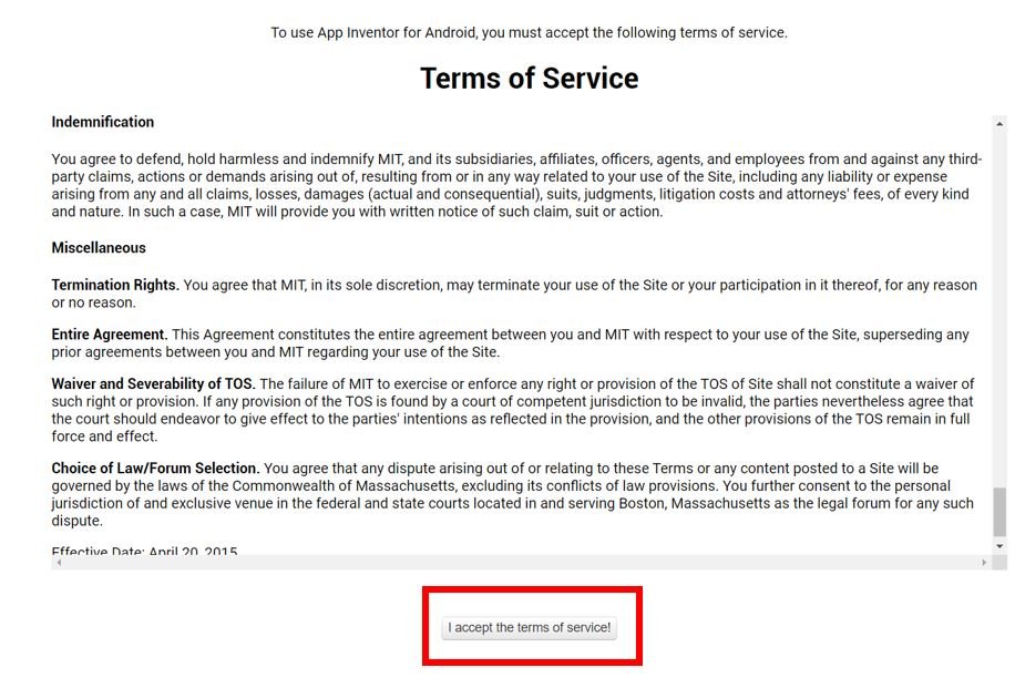
You will be redirected to a new window where you will be asked to sign in with your email account. After signing in you will have to accept the terms as shown below.
You will receive a welcome message. You can visit the link to get more information on how to install the inventor on your smartphone. Press ‘Continue’ to proceed. If you want, you can have a look at the tutorials being specified. Otherwise, go to ‘Start a blank project’ to start your app invention.

You will be asked to specify your project name. Choose an appropriate name. Click ‘ok.’
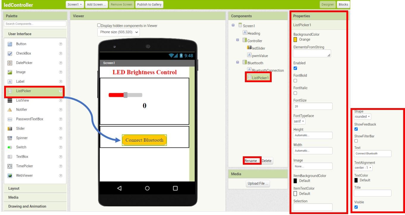
The following page will open. It is known as the Designer. This is where we will design the user interface of our app. We can add text, buttons, images and various other functionalities to our app by dragging and dropping components from the palette to the viewer. Then we will set their attributes through the ‘Properties’ column.

Create Design
Firstly, we will add a heading for our app. Go to Palette > User Interface and head over to ‘Label.’ Now click and drag the label. Drop it on the Viewer side. Now you will be able to view it in the viewer as well as in the components list. Rename it as ‘Heading‘ as shown in the Components section.
Head over to the ‘Properties’ to change the text, font size and colour. The label will automatically update in the viewer. Keep in mind the viewer will show you the final look of your app which will appear on your smartphone.
You can change the properties of the label to incorporate your preferred spacing dimension by changing the width and height of the label.

LED Controller Section
Next select VerticalArrangement from the Layout. Rename it ‘Controller‘ and set the Properties as shown below.

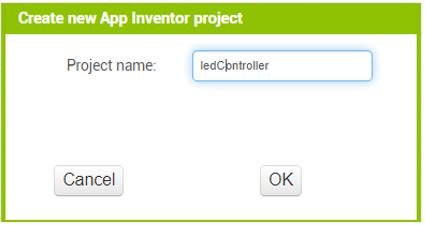
Next we will add the slider. Head over to User Interface > Slider and click and drag it to Controller. Rename it as ‘ledSlider‘ as shown in the Components section. Change the Properties of the slider by setting the color of the left and right side according to your preference, Width to 80%, MaxValue to 255, MinValue to 0. Moreover, Thumb is enabled and set to 0 position.
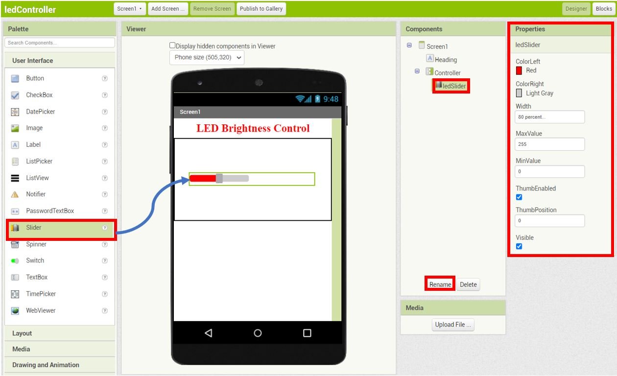
Next, we will add a Label beneath the slider. Rename it to ‘pwmValue‘ and set its Properties as shown below:
This will be used to display the thumb position of the slider. Hence the values will be in the range 0-255.
Bluetooth Section
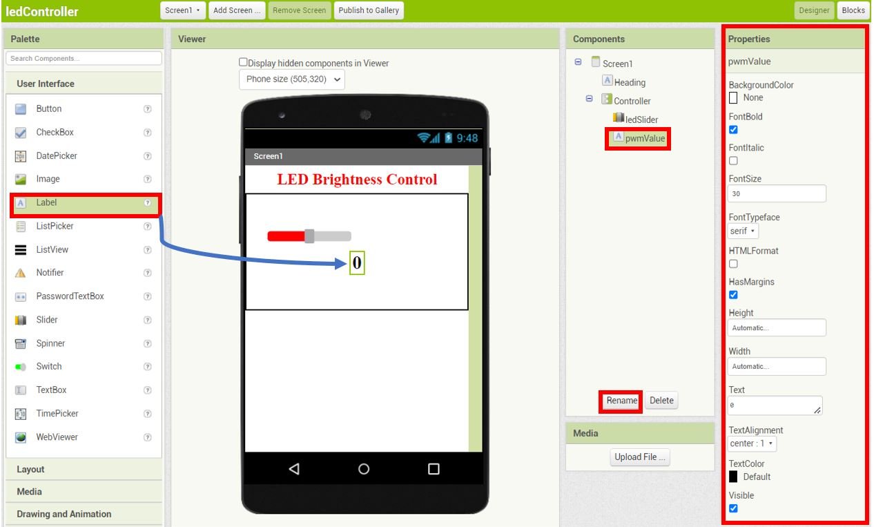
Next select VerticalArrangement from the Layout. Rename it ‘Bluetooth‘ and set the Properties as shown below.
Next add a label in the Bluetooth section and rename it as ‘BluetoothConnection‘ using the rename button found in the Components section.
Head over to the ‘Properties’ to change the text, font, font size and color of the this label. We have set the FontSize to 14, FontTypeface to serif, Height to Automatic, Width to Automatic, Text to Disconnected, TextAlignment to center : 1 and TextColor to None.

For the Connect Bluetooth button we will add a List Picker. Go to User Interface > ListPicker and drag and drop it beneath the BluetoothConnection label. Go to the ‘Properties’ of the ListPicker and set them as follows:
Add Bluetooth Client and Clock to MIT App Inventor
Go to Palette > Connectivity and click and drag BluetoothClient in the viewer. This is a non-visible component of our app and will let us connect it with our Bluetooth module.
Next head over to Palette > Sensors and drag and drop clock in the viewer. Rename it as ‘BluetoothClock.’ This is also a non-visible component of the app used for monitoring the time.

Blocks Layout
Now click on the ‘Blocks’ button found at the top of the window. A new editor will open up. Here we will design how our app will respond. We will assemble blocks in the workspace by clicking and dragging them.

Firstly, assemble the blocks for the Bluetooth connection as shown below.

Next, assemble the blocks for ledSlider as shown below. When the thumb of the slider is moved, the rounded off thumbPosition will be sent to Arduino via Bluetooth. The pwmValue label’s text will be set to the rounded off thumbPosition as well.

For more information regarding building your app in MIT App Inventor, follow this guide: App Inventor Tutorials.
Setting up App Inventor on Smartphone
Now, as we have built our app in MIT app inventor and have also written its code let’s move ahead and install the App Inventor in our smartphone. Through this, we will be able to access our app on our smartphone from anywhere around the world. Follow the steps closely.
Firstly, go to Play Store and install ‘MIT AI2 Companion.’

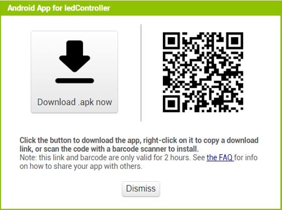
After you installed the application, open it. You will have to either scan a QR code or type a 6-character code.

To access these, go to MIT App Inventor main page where we initially built our app. Go to Build > Android App (.apk). After a few moments your barcode will get generated. You can either download the .apk file or scan the barcode using the MIT App Inventor.
After installing the .apk file on our android phone, we will be able to view the screen which we created.
Now, we will demonstrate the project.
Demonstration
Choose the correct board and COM port before uploading your code to the board.
Go to Tools > Board and select Arduino Module.

Next, go to Tools > Port and select the appropriate port through which your board is connected.
Click on the upload button to upload the code into the Arduino development board. After you have uploaded your code to the Arduino development board press its ENABLE button.

Open the MIT Companion app on your smartphone. Pair your android phone with HC-05 module. Now press the ‘Connect Bluetooth’ button.

Select HC-05 Bluetooth module to connect with.


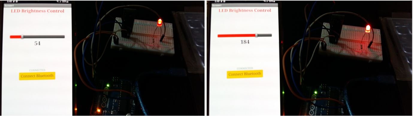
Now move the slider thumb to the right and the slider value will start increasing.

This will generate a PWM signal with the corresponding duty cycle value. Hence, the LED will start getting brighter. Once the value reaches 255, the LED will be the brightest. Then start, moving the slider thumb to the left thereby decreasing the slider value. This will cause the LED to fade until it turns OFF when the value reaches 0 again.
Video demo:
You may also like to read:
Dear sir/madam, first of all thanks a lot for this educational project. I am reaching to you to ask a question about this project; although I have followed all the instructions accordingly, I have not been able to increase or decrease the intensity of the led. Checking the serial port input I see that the data from the command block “call arduinoBluetoothClient.Send1ByteNumber number round get thumbPosition” are not showing up. Is there anything else I can do to fix this?