In this article, we will see an introduction to pulse width modulation. Pulse width modulation is also known as PWM. Pulse width modulation has many applications in digital communication, power electronics, auto intensity control of street lights, speed control of DC motors, and variable pwm to generate analog signals from digital signals using a digital-to-analog converter. There are many other applications for this technique. Two methods are used to generate PWM signals: the digital method and the analog method. We will discuss both methods at the end of this article. So let’s start with a basic introduction to pulse-width modulation. Pulse width modulation, or PWM, is a technique for getting analog results with digital means. It also has applications in inverters and DC-to-DC power supplies.
What is Pulse Width Modulation?
What can we do with PWM? PWM stands for pulse width modulation, and it consists of producing a square wave. We can control the up or high time in a PWM signal. The minimum and maximum voltages are the values that limit the wave’s oscillation; the space between them is called amplitude. A cycle is the interval of the wave where we can find one full repetition. The time a cycle takes to finish is called the time period. The time period of a signal is
Time period = on time + off time
Frequency of PWM
The frequency is 1 over a period, which gives us the count of cycles in a time unit. For example, if the timer period of a signal is 20 ms, its frequency will be 50 Hz, where Hz is a unit of frequency. It is read as hertz.
Frequency = 1 / timer period
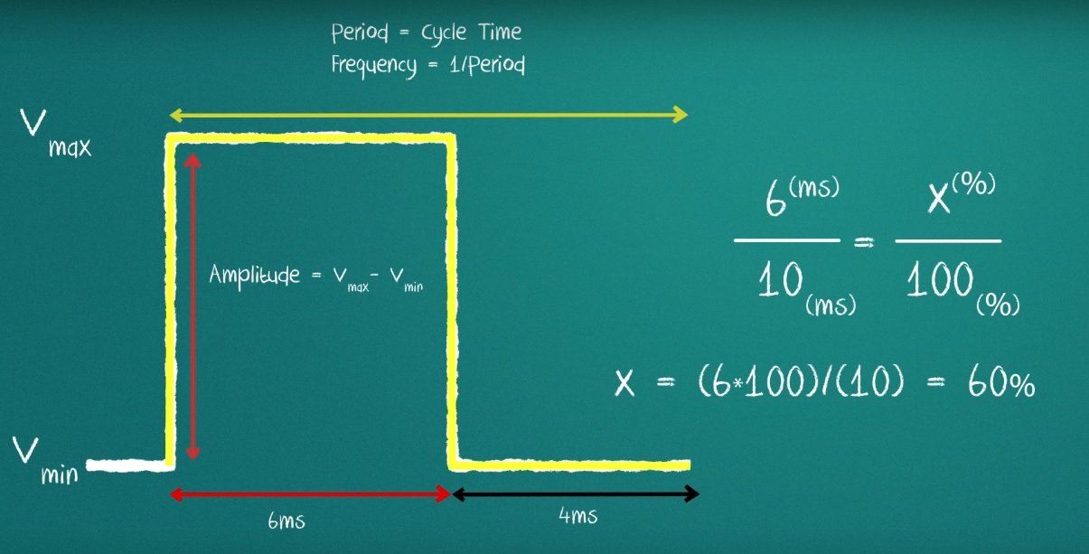
The picture below shows the amplitude and time period of a wave form.

What is Duty Cycle?
Duty Cycle is an important concept used in pulse width modulation. The duty cycle represents how much of the time the signal remains high in the total time period.
So, we can see the formula for duty cycle in the following expression:
Duty Cycle = (On time of signal / total timer period of signal)
How to Calculate Output Voltage of PWM Signal?
Now let’s see how to calculate a duty cycle. To calculate the duty cycle, we need to know how much of the period the signal is high. Let us set our high time at 6 milliseconds and our low time at 4 milliseconds. The total time period is 10 ms. Now let’s use a simple rule to calculate the percentage of the period in which the signal is high and relate it to the total time period.
Duty cycle = 6 ms / 10 ms = 0.6
By solving this, we get the duty cycle of 0.6, which is a unitless quantity. We always measure duty cycles in percentages. The maximum duty cycle can be 1 or 100% when the on-time or high-time of the signal is equal to the total time period of the signal. Similarly, the minimum duty cycle will be 0 or 0% when the signal is off for the total time period. We can see a picture below of signals with different duty cycles.

Amplitude of PWM
Amplitude of pulse The amplitude of pulse width modulation is another important concept to discuss to fully understand this concept. This amplitude is the difference between the maximum voltage and the minimum voltage of the signal.
Amplitude = Vmax – Vmin
In the case of digital signals, the minimum voltage is mostly zero. So amplitude is the peak voltage of the signal. Let’s imagine a PWM signal that oscillates between 0 and 5 volts. Let’s say this signal has a duty cycle of 50%. Something interesting will happen to the output voltage instead of being 5 volts as expected. Simply put, it will now be 2.5 volts.

Output Voltages of PWM
When we apply this square wave of 50% duty cycle to an LED, we will get a voltage of 2.5 across the light-emitting diode. Because when we apply a square wave of 50% duty cycle as an input voltage source, the formula for the output voltage is given by:
Vout = D x Vmax
Where D is the duty cycle of the pulse width modulation signal, or square wave. We multiply the maximum voltage by the duty cycle. According to the above formula for output voltage, we can clearly see a direct relation between output voltage and duty cycle. The maximum voltage or amplitude of the signal remains constant. To get a higher voltage, we need a higher duty cycle signal. To get a lower voltage at the output, we need to apply a lower duty cycle signal.
Maximum output voltage will be equal = Vmax when duty cycle = 100% or 1
Maximum output voltage will be equal = 0 when duty cycle = 0
A similar concept is used in street lights to control the intensity of street lights. The same method is used in power electronics circuits to step down voltages using buck converter circuits.
So now we have learned the basic concepts of pulse width modulation, like duty cycle, on-time of signal, off-time of signal, time period of PWM, and its amplitude. In the rest of this article, we will explain different methods used to generate PWM signals.
Pulse Width Modulation Generation Techniques
Two methods are used to generate PWM:
- To generate PWM signals using digital circuits like microcontrollers.
- To generate PWM signals using analog circuits like operational amplifiers and comparator circuits.
PWM Generation Using Microcontroller
The recommendation is to use a microcontroller like an Arduino to generate a digital signal with a variable duty cycle. These microcontrollers have built-in modules available to generate digital signals. We can easily set the duty cycle with the help of microcontroller programming in C. We already posted an article on these concepts. Check out these posts to learn how to generate PWM using a microcontroller.
PWM Generation Using Analog Circuits
The simplest way to generate a PWM signal is to use an operational amplifier. To generate a digital signal with an operational amplifier, we use the operational amplifier as a comparator circuit. An operational amplifier consists of two terminals: a non-inverting terminal and an inverting terminal. We apply a triangular wave at the non-inverting input and a control voltage input at the inverting pin of the operational amplifier. The picture below shows the whole process of generating a PWM signal using an operational amplifier.
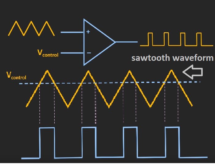
So to understand the workings of this method, we first need to understand the workings of an operational amplifier, such as a comparator circuit. As we can understand from the above pictures, when we apply the triangular voltage to the non-inverting input and it is less than the control voltage that we apply to the inverting pin of the operational amplifier, the output of the comparator circuit will be low, and whenever the voltage of the triangular signal is greater than the control voltage, the output of the comparator will be high. So the on-time of the digital signal or pulse width modulation depends on the magnitude of the control voltage. So its mean control voltage and duty cycle are inversely proportional to each other. because the duty cycle is directly proportional to the on-time of the PWM signal.
To get a higher duty cycle, we need to decrease the value of the control voltage. To get a lower duty cycle, we need to increase the value of the control voltage. So this is how easy it is to generate PWM with the help of analog electronics components.
Other Methods to Generate PWM
There are many integrated circuits available on the market that produce PWM signals, and they also have the ability to generate variable duty cycle digital signals. The names of some of them are given below:
Applications of Pulse Width Modulation
We have mentioned a few applications at the start of this article. But you can see our project in which we used PWM for various applications like inverters, three-phase inverters, and power electronics.
- Solar inverter using SG3525
- SPWM generation using pic16f877a
- Three phase sine wave inverter using Arduino
- Three phase SVPWM using Pic microcontroller
Conclusion
In conclusion, this tutorial provides an in-depth overview of pulse-width modulation. It covers a basic introduction along with the properties of PWM signals. Then we discuss the techniques to generate the PWM signal and its various applications. Hopefully, this was helpful in expanding your knowledge of PWM’s signal generation and properties.
You may also like to read:
- Raspberry Pi Pico PWM MicroPython LED Fading Examples
- STM32 Blue Pill Timer in PWM Mode with LED Dimmer Example
- ESP8266 NodeMCU PWM Slider Web Server – Control LED Brightness
- MicroPython: PWM with ESP32 and ESP8266 – LED fading and Brightness Control Examples
- PWM TM4C123 – Generate PWM Signals with Tiva C Launchpad
- ESP32 PWM with Arduino IDE (LED Fading Example)
This concludes today’s article. If you face any issues or difficulties, let us know in the comment section below.