In this tutorial, we will learn how to use the PWM channels of the Raspberry Pi Pico using MicroPython in Thonny IDE and uPyCraft IDE. First, we will explore which GPIO pins on the Pico board are capable of generating pulse width modulation signals. After that, we will look at how to produce PWM signals using those GPIO pins. Finally, we will implement two practical examples: LED fading and LED brightness control using a potentiometer.
Recommended Components
The following components are used in this project or are helpful for getting started with Raspberry Pi Pico development.
| Component | How it’s used in this project | Buy on Amazon |
|---|---|---|
| Raspberry Pi Pico | The RP2040 microcontroller board used in this tutorial. | Check Price |
| LED Assortment Kit | LEDs whose brightness is controlled by the PWM signal. | Check Price |
| Resistor Kit | Includes the 220-ohm current-limiting resistor for the LED. | Check Price |
| Breadboard | Solderless breadboard for building the circuit. | Check Price |
| Jumper Wires | Male-to-male / male-to-female wires for the connections. | Check Price |
As an Amazon Associate we earn from qualifying purchases. Prices and availability are accurate as of the date/time indicated and are subject to change.
Prerequisites: Raspberry Pi Pico PWM Tutorial
Before getting started, make sure you have already completed the following steps:
- Downloaded and installed the latest version of Python 3 on your PC.
- Downloaded and installed the latest version of Thonny IDE.
- Flashed MicroPython firmware onto the Raspberry Pi Pico.
If you are unsure how to complete any of these steps, follow this detailed getting started guide:
If you prefer to use uPyCraft IDE instead, check out this guide:
PWM Introduction
PWM stands for Pulse Width Modulation. It is a technique used by microcontrollers — in our case, the Raspberry Pi Pico — to simulate an analog output using a digital signal. The output signal is a square waveform that is either HIGH or LOW at any given moment. When using a 3.3V power supply, the HIGH level corresponds to 3.3V and the LOW level corresponds to 0V.
PWM is extremely useful in a wide range of real-world applications. It is commonly used for controlling the brightness of LEDs, adjusting the speed of DC motors, generating audio tones, controlling servo motor positions, and communicating with certain sensors and peripherals. Understanding PWM is a fundamental skill for any embedded systems developer.
The key characteristic of a PWM signal is that the microcontroller can control how long the signal stays HIGH versus LOW during each cycle. This control is achieved by adjusting two parameters: the duty cycle and the frequency. Let us take a closer look at both.
What is Duty Cycle?
The duty cycle is the percentage of time during which the PWM signal remains HIGH within a single period. For example, if the signal is always LOW, the duty cycle is 0%. If it is always HIGH, the duty cycle is 100%. By varying the duty cycle between these two extremes, you can control the average power delivered to a load such as an LED or motor.
For instance, a 25% duty cycle means the signal is HIGH for only one quarter of the total period, resulting in the LED glowing at roughly 25% of its full brightness. A 75% duty cycle means the signal is HIGH for three quarters of the period, making the LED appear much brighter. The formula for calculating the duty cycle is:
Duty Cycle = ON Time / Total Period × 100%

What is Frequency?
The frequency of a PWM signal determines how many complete ON/OFF cycles occur per second. It defines how quickly the signal switches between HIGH and LOW states. The period is the inverse of the frequency, and it equals the sum of the ON time and the OFF time.
For example, if the total period of a signal is 20 milliseconds, the frequency is 50Hz. A higher frequency means the signal completes more cycles per second, which is often desirable when controlling motors or audio devices to avoid audible noise or flickering. For LED control, a frequency of 1000Hz (1kHz) is a practical starting point since it is well above the threshold of human perception.
Frequency = 1 / Time Period
Time Period = ON time + OFF time
PWM Pins on Raspberry Pi Pico
The Raspberry Pi Pico is based on the RP2040 microcontroller, which contains 8 PWM slices (also called PWM blocks). Each slice provides two independent PWM output channels, labeled A and B. This gives a total of 16 PWM output channels available across the GPIO pins of the Pico board.
An important detail to note is that certain GPIO pins share the same PWM channel. For example, GPIO0 and GPIO16 both map to PWM channel 0A. If you configure both of these pins as PWM outputs, they will produce the same signal. However, in most projects you will only use one GPIO pin per channel, so this rarely causes any issues.
All 26 exposed GPIO pins on the Pico can be configured to output a PWM signal. The table below shows which PWM channel each GPIO pin maps to:

| GPIO | 0 | 1 | 2 | 3 | 4 | 5 | 6 | 7 | 8 | 9 | 10 | 11 | 12 | 13 | 14 | 15 | 16 | 17 | 18 | 19 | 20 | 21 | 22 | 23 | 24 | 25 | 26 | 27 | 28 | 29 |
| PWM Channel | 0A | 0B | 1A | 1B | 2A | 2B | 3A | 3B | 4A | 4B | 5A | 5B | 6A | 6B | 7A | 7B | 0A | 0B | 1A | 1B | 2A | 2B | 3A | 3B | 4A | 4B | 5A | 5B | 6A | 6B |
How to Initialize PWM in MicroPython for Raspberry Pi Pico
Setting up a PWM signal in MicroPython for the Raspberry Pi Pico is straightforward. Follow the steps below to configure and use a PWM-capable GPIO pin:
- Choose a PWM-capable GPIO pin. Any GPIO pin on the Pico can be used for PWM output, as shown in the table above.
- Set the frequency. Define the frequency of your PWM signal in Hertz (Hz). A value of 1000Hz works well for LED control.
- Set the duty cycle. The Raspberry Pi Pico hardware uses a 12-bit PWM counter, but MicroPython scales this to a 16-bit resolution. This means the duty cycle value can range from 0 (0% — always OFF) to 65535 (100% — always ON). Using 16-bit resolution gives you finer control over the output brightness or speed.
The key MicroPython methods you will use for PWM are:
- PWM(Pin(n)) — Creates a PWM object on GPIO pin number n.
- .freq(value) — Sets the PWM signal frequency in Hz.
- .duty_u16(value) — Sets the duty cycle using a 16-bit value (0 to 65535).
- .deinit() — Disables the PWM output on the pin when it is no longer needed.
MicroPython LED Fading Example using PWM
In this first example, we will build a simple circuit that gradually fades an LED from OFF to its full brightness by incrementally increasing the duty cycle. This technique is commonly known as LED fading or LED breathing and is widely used in status indicators, mood lighting, and visual feedback systems.
Required Components
- Raspberry Pi Pico
- Breadboard
- One LED (any color)
- One 220-ohm resistor
- Connecting wires
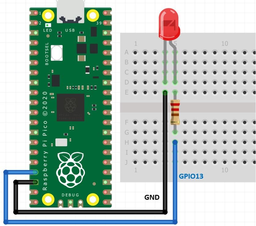
Connection Diagram
Connect the LED’s anode (longer leg) to GPIO13 of the Raspberry Pi Pico through a 220-ohm current-limiting resistor. Connect the LED’s cathode (shorter leg) to GND. The 220-ohm resistor is important because it protects the LED from drawing too much current, which could permanently damage both the LED and the Pico’s GPIO pin. You can also use any other available PWM-capable pin if GPIO13 is occupied. Make your circuit connections as shown in the diagram below:
MicroPython PWM Library
To use PWM in MicroPython on the Raspberry Pi Pico, follow these steps:
- Import the PWM and Pin classes from the
machinemodule. This module provides direct access to the hardware peripherals of the Pico. - Create a PWM object by passing a Pin object as its argument. For example,
led = PWM(Pin(13))creates a PWM output on GPIO13. - Set the frequency using the
.freq()method. For example,led.freq(1000)sets the signal frequency to 1000Hz (1kHz). - Set the duty cycle using the
.duty_u16()method. For example,led.duty_u16(32768)sets the duty cycle to 50%. MicroPython uses 16-bit resolution for the duty cycle on the Pico, so values range from 0 (0%) to 65535 (100%).
MicroPython PWM Script
The following script fades the LED from completely off (0% duty cycle) to its maximum brightness (100% duty cycle) by incrementally increasing the duty cycle value inside a for loop. Once it reaches the maximum value, the loop restarts from 0, creating a continuous fading effect.
from machine import Pin, PWM
from time import sleep

led = PWM(Pin(13))
led.freq(1000)

while True:
    for duty in range(0, 65535):
        led.duty_u16(duty)
        sleep(0.0001)
How the Code Works
Importing PWM and Pin Classes
At the top of the script, we import the PWM and Pin classes from the machine module. The machine module in MicroPython provides access to the hardware peripherals of the microcontroller. We also import sleep from the time module to introduce small delays between each duty cycle update, allowing the fading effect to be visible to the human eye.
from machine import Pin, PWM
from time import sleep
Creating the PWM Pin Object
We create a PWM object named led by wrapping a Pin object inside the PWM() constructor. The argument Pin(13) specifies that we are using GPIO13 as our PWM output pin. Next, we set the frequency of the PWM signal to 1000Hz using the .freq() method. This frequency is high enough that the human eye cannot perceive individual ON/OFF cycles, resulting in a smooth and steady light at whatever brightness level the duty cycle dictates.
led = PWM(Pin(13))
led.freq(1000)
Generating a Variable Duty Cycle
Inside the infinite while True loop, we use a for loop with Python’s range() function to iterate the duty cycle value from 0 to 65534, incrementing by 1 on each iteration. The range(0, 65535) call generates values starting at 0 and going up to 65534 (the stop value of 65535 is excluded by default). During each iteration, the current duty cycle value is passed to led.duty_u16(duty), which updates the PWM output immediately. A short delay of 0.1 milliseconds is also introduced using sleep(0.0001) to slow the fading effect to a pace visible to the human eye.
while True:
    for duty in range(0, 65535):
        led.duty_u16(duty)
        sleep(0.0001)
As the duty cycle increases, the average voltage supplied to the LED increases proportionally, causing the LED to gradually brighten from fully OFF to fully ON.
Demonstration
To test this example, copy the script into Thonny IDE and connect the LED to GPIO13 of your Raspberry Pi Pico as shown in the wiring diagram. Run the script by pressing the green play button in Thonny. You should observe the LED gradually increasing in brightness from completely off to fully lit, then resetting and repeating. The video below demonstrates this behavior:
If you have access to an oscilloscope, you can also connect it to GPIO13 to observe the PWM waveform directly. You will see that the signal frequency remains fixed at 1kHz while the duty cycle gradually increases from 0% to 100% as the loop progresses.
Raspberry Pi Pico Brightness Control using PWM and a Potentiometer
In this second example, we will control the brightness of an LED using a potentiometer. Rather than automatically stepping through duty cycle values as in the previous example, this project reads an analog voltage from the potentiometer using the Pico’s built-in ADC (Analog-to-Digital Converter) and maps it directly to the PWM duty cycle. This allows you to manually control the LED brightness in real time by simply turning the potentiometer knob.
This type of control is very common in real-world applications. For example, the same principle is used to control the speed of a fan by reading a temperature sensor, or to adjust audio volume by reading a rotary encoder. Understanding how to combine ADC input with PWM output is an essential embedded systems skill.
- Raspberry Pi Pico
- Breadboard
- One LED (any color)
- One 220-ohm resistor
- One 10k ohm potentiometer
- Connecting wires
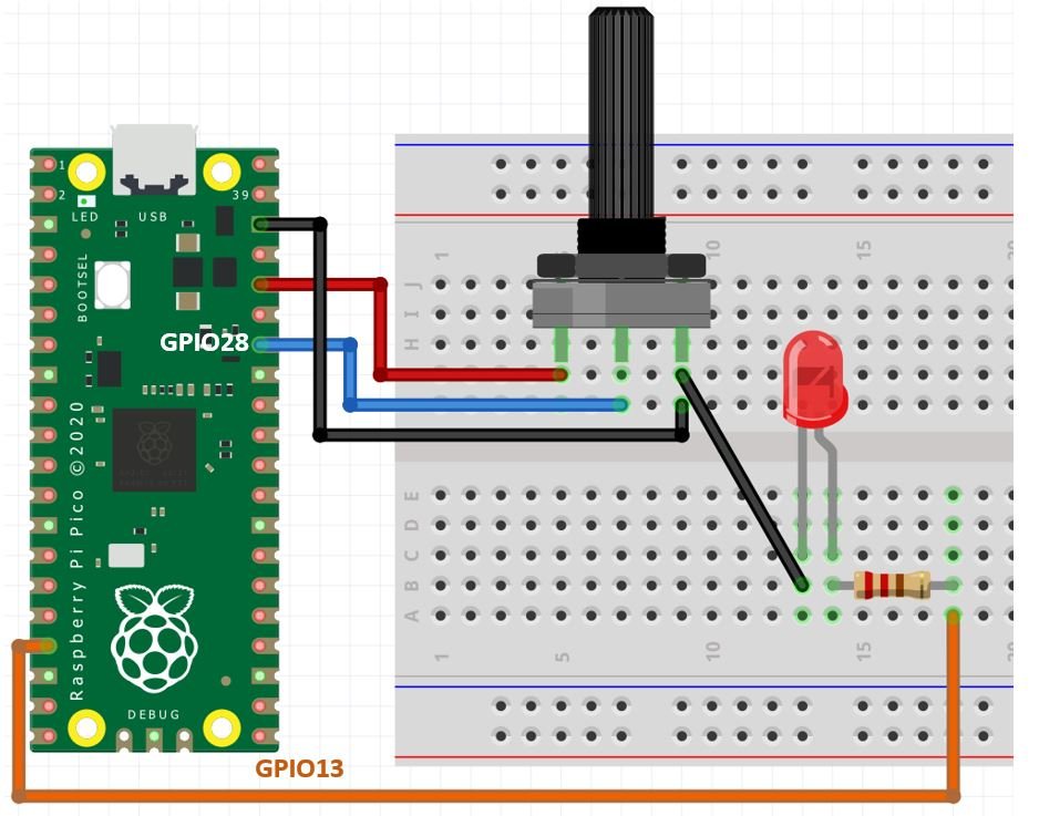
Connect the components as shown in the schematic diagram below. The potentiometer’s middle (wiper) terminal connects to GPIO28 (ADC2), one outer terminal goes to 3.3V, and the other outer terminal goes to GND. The LED anode connects to GPIO13 through the 220-ohm resistor, and the cathode connects to GND.
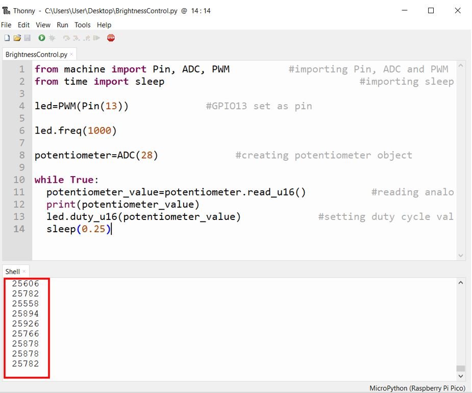
Brightness Control MicroPython Script
from machine import Pin, ADC, PWM          # Importing Pin, ADC and PWM classes
from time import sleep                     # Importing sleep for delay

led = PWM(Pin(13))       # Configure GPIO13 as PWM output
led.freq(1000)           # Set PWM frequency to 1000 Hz

potentiometer = ADC(28)  # Create an ADC object on GPIO28 (ADC channel 2)

while True:
    potentiometer_value = potentiometer.read_u16()   # Read the analog value (0-65535)
    print(potentiometer_value)                       # Print the value to the serial console
    led.duty_u16(potentiometer_value)                # Set PWM duty cycle equal to ADC reading
    sleep(0.25)                                      # Wait 250ms before next reading
How the Code Works
Importing Libraries
We begin by importing three classes from the machine module: Pin, ADC, and PWM. The ADC class allows us to read analog voltage values from GPIO pins that support analog-to-digital conversion. We also import the sleep function from the time module to add a short delay between each ADC reading.
from machine import Pin, ADC, PWM
from time import sleep
Setting Up the PWM Output
We configure GPIO13 as a PWM output pin and set the frequency to 1000Hz. This is the same setup as the previous LED fading example. The variable led is our PWM object and will be used to control the brightness of the LED.
led = PWM(Pin(13))
led.freq(1000)
Setting Up the ADC Input
The Raspberry Pi Pico has three ADC-capable GPIO pins: GPIO26 (ADC0), GPIO27 (ADC1), and GPIO28 (ADC2). We create an ADC object on GPIO28. The potentiometer is connected to this pin, so rotating the knob changes the voltage at this pin between 0V and 3.3V.
potentiometer = ADC(28)You can read more about using ADC with the Pico in this article: Raspberry Pi Pico ADC with Voltage Measurement Examples
Reading the Analog Signal and Setting the Duty Cycle
Inside the while True loop, we call potentiometer.read_u16() to read the current analog value from the potentiometer. This method returns an unsigned 16-bit integer in the range of 0 to 65535, corresponding to the analog voltage range of 0V to 3.3V. Because both the ADC read range and the PWM duty cycle range are 0 to 65535, we can directly assign the ADC reading to the duty cycle without any additional scaling or conversion. The current value is also printed to Thonny’s serial console using print(), which is useful for debugging and verifying the readings in real time. A 250ms delay is added using sleep(0.25) to prevent flooding the console with too many readings per second.
while True:
potentiometer_value = potentiometer.read_u16()
print(potentiometer_value)
led.duty_u16(potentiometer_value)
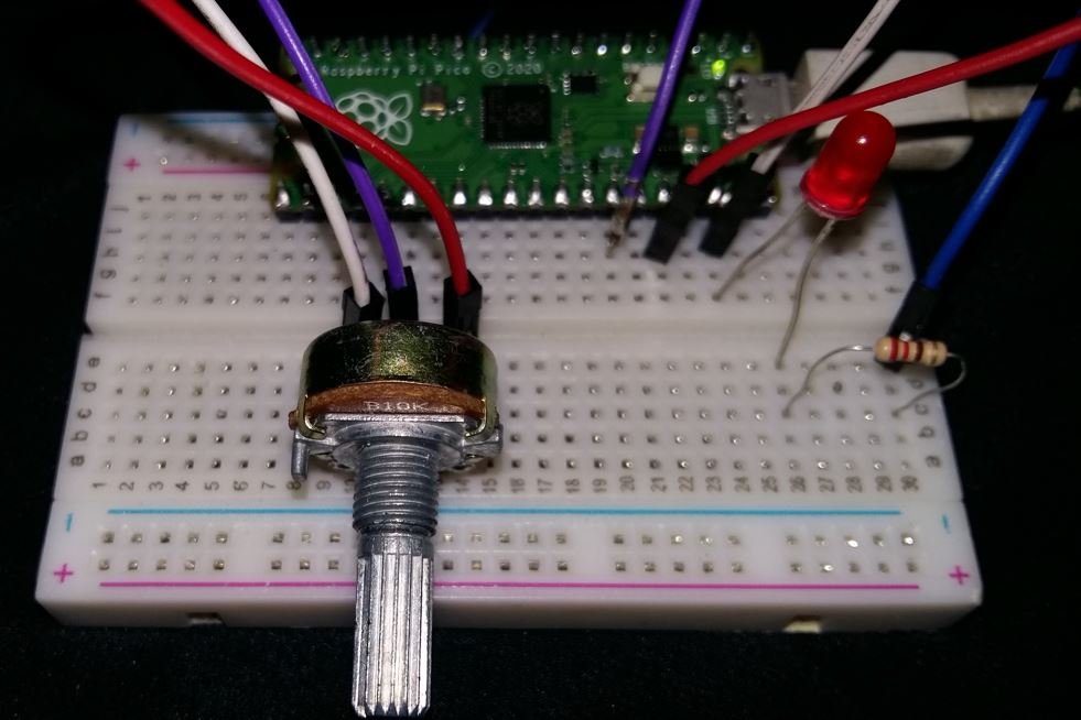
sleep(0.25)When you run this script and rotate the potentiometer knob, you will see the ADC values printed in Thonny’s shell window updating approximately every 250 milliseconds. At the same time, the LED will respond to the potentiometer position, becoming brighter as the value increases and dimmer as it decreases.
As you turn the potentiometer knob clockwise, the ADC reading increases, the duty cycle increases, and the LED becomes brighter. Turning it counterclockwise decreases the ADC reading, lowers the duty cycle, and dims the LED accordingly.
Common Issues and Troubleshooting
If the LED does not light up or behave as expected, check the following:
- Incorrect wiring: Double-check that the LED’s anode is connected to the GPIO pin (through the resistor) and the cathode is connected to GND. LEDs are polarized and will not work if connected in reverse.
- Missing current-limiting resistor: Always use a resistor in series with the LED. Without it, excessive current can permanently damage both the LED and the Pico’s GPIO pin.
- Wrong GPIO pin: If you changed the GPIO pin in the code, make sure the physical wiring matches. All GPIO pins on the Pico support PWM, so any pin will work.
- MicroPython not flashed: If the script does not run at all, make sure you have correctly flashed the MicroPython firmware onto the Pico. Hold the BOOTSEL button while connecting via USB, then drag and drop the MicroPython UF2 firmware file onto the Pico’s storage drive.
- Potentiometer not reading correctly: Ensure the potentiometer’s wiper terminal is connected to GPIO28, one outer terminal to 3.3V, and the other to GND. If the readings are reversed, swap the 3.3V and GND connections on the outer terminals.
Conclusion
In this tutorial, we learned how to use the PWM module of the Raspberry Pi Pico with MicroPython. We covered the fundamentals of PWM including duty cycle and frequency, explored the PWM pin mapping of the Pico board, and implemented two practical examples: an automatic LED fading effect and a manually controlled LED brightness using a potentiometer and ADC. These techniques form the foundation for a wide range of embedded systems projects involving motor control, analog signal generation, and human-machine interfaces.
You may also like to read: