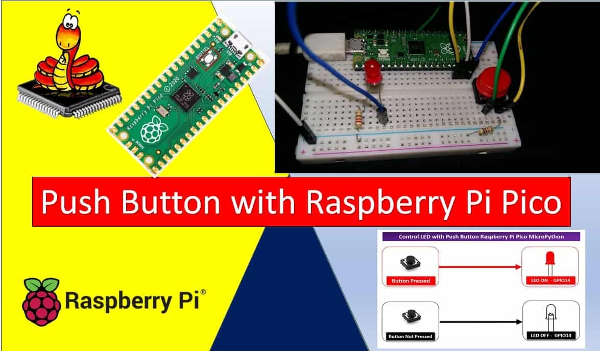
In this tutorial, we will learn how to use the GPIO pins of the Raspberry Pi Pico as digital input pins and interface a push button using MicroPython. In the previous tutorial, we learned how to use the GPIO pins of the Pi Pico board as output pins. However, in this tutorial, we will explore how the same GPIO pins can be utilized to acquire digital inputs from external modules. Specifically, we will demonstrate how to interface a push button with the Raspberry Pi Pico. By reading the state of the push button using an input pin on the Pico board, we will control an LED which will be connected to another GPIO pin.
Recommended Components
The following components are used in this project or are helpful for getting started with Raspberry Pi Pico development.
| Component | How it’s used in this project | Buy on Amazon |
|---|---|---|
| Raspberry Pi Pico | The RP2040 microcontroller board used in this tutorial. | Check Price |
| Tactile Push Buttons | Momentary push buttons read as the digital input. | Check Price |
| LED Assortment Kit | Standard LEDs driven by the GPIO output pin. | Check Price |
| Breadboard | Solderless breadboard for building the circuit. | Check Price |
| Jumper Wires | Male-to-male / male-to-female wires for the connections. | Check Price |
As an Amazon Associate we earn from qualifying purchases. Prices and availability are accurate as of the date/time indicated and are subject to change.
Prerequisites
Before we start this lesson, please make sure that you are familiar with and have the latest version of Python 3 installed on your system. Additionally, ensure that you have set up MicroPython on your Raspberry Pi Pico and have a functioning Integrated Development Environment (IDE) for programming. We will be using the Thonny IDE, which we used in a previous tutorial to learn how to blink and chase LEDs using MicroPython. If you haven’t followed our previous tutorial, you can find it here:
If you are using uPyCraft IDE, you can check this getting started guide:
GPIO Pins Raspberry Pi Pico
GPIO pins act as both input and output pins with an exception for a few. We will be using the GPIO Pins as digital input and as digital output pins in our Raspberry Pi Pico, this time when connecting the push button and the LED respectively. One digital pin will be connected to the push button and another one for the LED. We will be taking in the digital input from the push button and acquiring the digital output from the LED.
Below is the diagram showing the GPIO pins for Raspberry Pi Pico which we will be using to connect the push button and the LED.

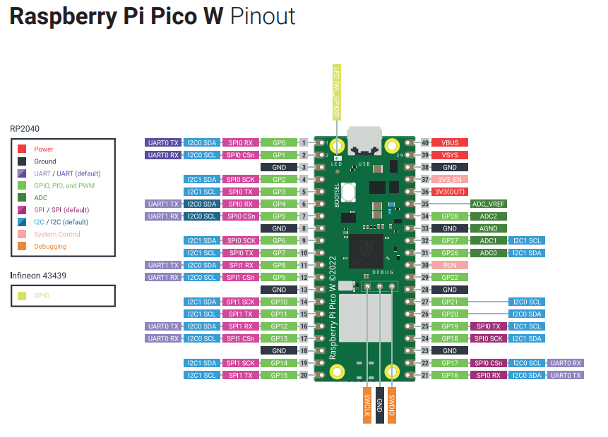
As shown in the above diagram we will be using GPIO 14 to connect the LED and GPIO 13 to connect the push button.
You should read the following article to learn more about the GPIO pins of Raspberry Pi Pico:
MicroPython Digital Inputs and Outputs
In this section, we will see how to configure GPIO pins in MicroPython to control digital outputs and read digital inputs.
Digital Output
To use a GPIO pin as a digital output in MicroPython, you can follow these steps:
- Import the necessary modules:
from machine import Pin- Create an instance of the
Pinclass and specify the GPIO pin number and mode (output):
led_pin = Pin(14, Pin.OUT)- Turn on the LED by setting the output pin to logic high:
led_pin.value(1)- Turn off the LED by setting the output pin to logic low:
led_pin.value(0)Digital Input
To use a GPIO pin as a digital input in MicroPython, you can use the value() function to read the state of the pin. Here’s how you can do it:
- Import the necessary modules:
from machine import Pin- Create an instance of the
Pinclass and specify the GPIO pin number and mode (input):
button_pin = Pin(13, Pin.IN)- Read the state of the input pin using the
value()function:
state = button_pin.value()- Process the state of the input pin as needed in your application.
Push Button Interfacing Raspberry Pi Pico
We will read the state of the push button. The push button will give two logical states: either high or low. We will connect the push button to the Raspberry Pi Pico board using a resistor.
When we want to interface a push button with a microcontroller, we actually want to read the state of the push button either pressed or not pressed state. When a push button is pressed or unpressed, it provides either logic high or logic low output depending on the configuration mode in which the push button circuit is designed.
There are two configuration modes to interface a push button with Raspberry Pi Pico. Let’s discuss both these modes one by one.
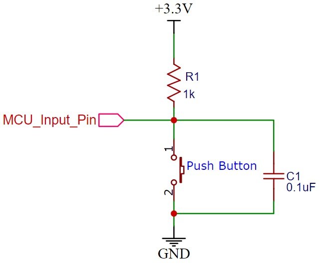
Pull-Up Mode
In Pull-up mode, when a push button is not pressed, a logic high input appears at MCU_Input_Pin. Because a 3.3V signal appears on the input terminal through an R1 resistor. On the contrary, when the push button is pressed, metallic contacts of the push button make contact with the ground terminal and the input terminal. Therefore, a logic low input will reflect on the digital input pin of the Raspberry Pi Pico. In short, by reading this state of the push button with a digital input pin of a microcontroller, we can identify whether a push button is pressed or not. The following schematic diagram shows the connection of a push button with a pull-up resistor.
Pull-Down Mode
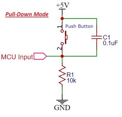
In Pull-down mode, when a push button is not pressed, a logic low input appears on the Raspberry Pi Pico GPIO pin. Because a ground reference signal appears on the input terminal through an R1 resistor. On the contrary, when the push button is pressed, metallic contacts of the push button make contact with the +5V signal and the input terminal. Therefore, a logic high input reflects on the digital input pin of Raspberry Pi Pico. The following schematic diagram shows the connection of a push button with a pull-down resistor.
For demonstration, we will control an LED with a push button using Raspberry Pi Pico GPIO pins as digital read and write pins.

Connection Diagrams
Assembling the Circuit of push button with Raspberry Pi Pico. Now we will connect the circuit with the LED and push button. The following components are required.
Required Components:
- Raspberry Pi Pico
- One LED
- 220-ohm resistor
- 10k ohm resistor
- Breadboard
- Connecting wires
The below picture shows the schematic for Raspberry Pi Pico with a push button and LED. Assemble your circuit as follows:
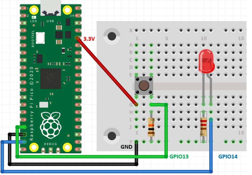
In the above schematic, we can see that GPIO14 is connected to the anode pin of the LED and the cathode pin is connected to the common ground through the 220-ohm resistor.
A push button has four terminals. One terminal is powered by 3.3 volts from the Raspberry Pi Pico, and the other terminal is connected to GPIO13 and the 10k ohm resistor, which acts as a pull-down resistor. The other end of the resistor is connected to the common ground.
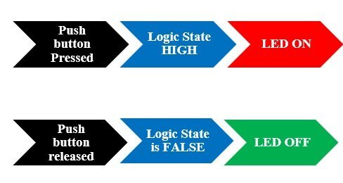
When the push button is pressed, a logic state of high (1) will be passed on GPIO13 and the push button input will be in a high state. When the button is released a logic state of low (0) will be passed on GPIO13 and the push button input will be in a logic state LOW. We will read these two states of the push button and turn on and turn off the LED accordingly.
MicroPyhton Control Digital Outputs and Read Digital Inputs
We will write a MicroPython script to control an LED with a push button for Raspberry Pi Pico. Follow the steps in the particular order:
Open Thonny IDE. Create a new file by clicking on the ‘New File’ icon or go to File > New.
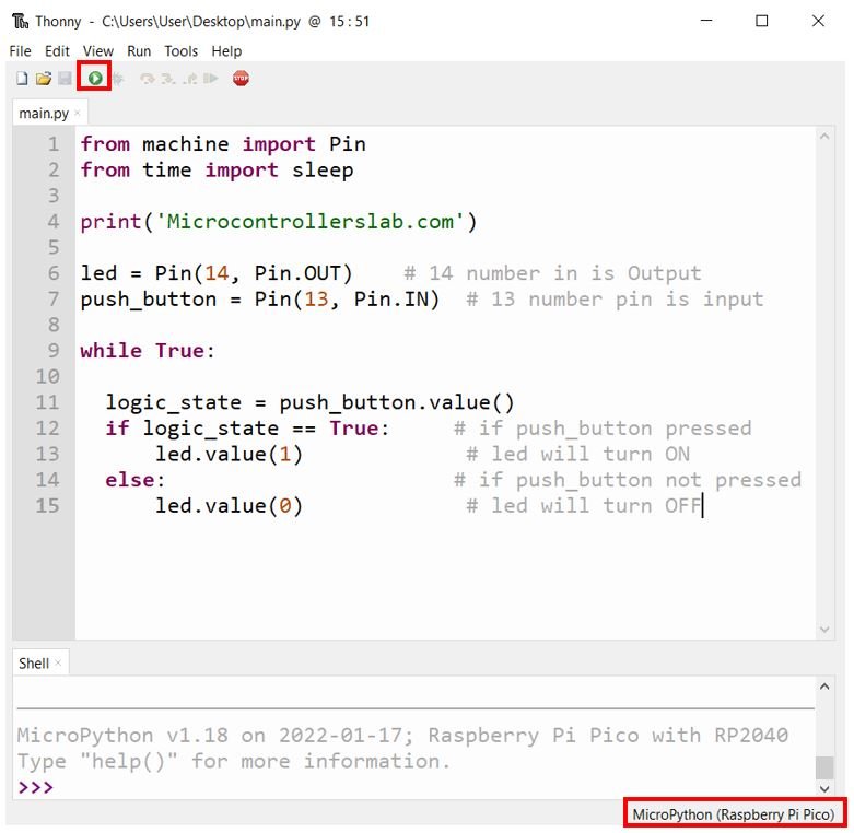
The following code reads the state of the push button and lights up the LED accordingly. Copy the following code in the new file that you just opened and save it as a main.py file in Thonny IDE.
from machine import Pin
from time import sleep

print('Microcontrollerslab.com')

led = Pin(14, Pin.OUT)    # 14 number in is Output
push_button = Pin(13, Pin.IN)  # 13 number pin is input

while True:

  logic_state = push_button.value()
  if logic_state == True:     # if push_button pressed
      led.value(1)             # led will turn ON
  else:                       # if push_button not pressed
      led.value(0)             # led will turn OFF
After you have copied the following code onto the file click on ‘Save’ icon to save your program code on your PC. Save your file by giving it a name main.py and save according to your preference by giving the directory.
After we have saved the code press the Run button to upload the code to your Raspberry Pi Pico module. Before uploading code make sure the correct board is selected.
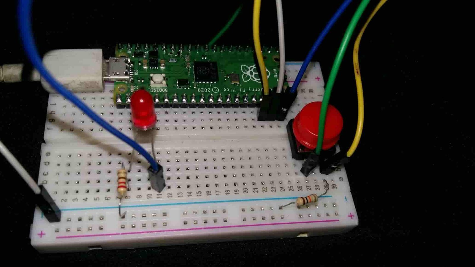
Now if you press the push button, the LED will glow and if you leave the push button, a LED will remain off.
How Code Works?
Firstly, we will import the library for the Pin class from the machine module. To interact with the input/output GPIOs, we will import the machine module that contains classes to interact with the GPIOs. We will import the Pin class to interact with the pins.
from machine import Pin MicroPython Define Digital Output
To set a GPIO on or off, we will set it as an output. The first argument in the Pin() class is the pin number on which we are configuring the output. The output is on GPIO14 which is connected to the LED. The second argument shows the pin mode e.g. digital input or digital output mode. As we are configuring pin 14 as the digital output we gave, specifies it as ‘Pin.Out’. This is stored in the object ‘led’.
led = Pin(14, Pin.OUT) MicroPython Define Digital Input
To get the value of a GPIO, we will create a Pin object and set it as an input using ‘Pin.IN’ as the second argument in our Pin() class. The input is on GPIO13 which we specified in the first argument and is connected to the push button. This is stored in the object ‘push_button’.
push_button = Pin(13, Pin.IN) The push button acts as the input and the LED as the output.
We use an infinite loop so we can perform our project endlessly and it does not come to a halt.
while True: #infinite loopRead Push Button State
In order to obtain the value of the input GPIO, we use the function value() on the Pin object without passing any argument inside it. In this case, push_button.value() was used in our program code. The value we would obtain from this is getting stored in the variable logic_state which denotes the logic state of the push button.
logic_state=push_button.value() #storing the value of the push button state in the variable logic_stateIf-Else Statement MicroPython
In this step, we are using an if-else loop. This line states if the push button logic state is TRUE that means 1
if logic_state==True: #if state of button is logic 1To control the output of the GPIO, we can use the value() function on the Pin object and pass 1 as an argument. This sets the output to a logic state of HIGH, turning the LED on.
led.value(1) #LED is ONThis means that the output, which is the LED, has a logic state of LOW. Hence, the LED will be turned off.
else:
led.value(0)    #LED is OFF
In this whole if-else loop, if the logic state of the push button is high meaning the push button is pressed, the LED will be ON and if the logic state of the push button is low meaning the push button was released, then the LED will be OFF.
In this tutorial, we learned how to use GPIO pins as both inputs and outputs in the same project by controlling the on/off mechanism of an LED using a push button in Micro-python for Raspberry Pi Pico.
Conclusion
In this tutorial, we learned how to interface a push button with Raspberry Pi Pico using MicroPython firmware. We learned how to use GPIO pins as digital input and output, and we saw the circuit diagrams and connection details for connecting a push button and an LED to the Raspberry Pi Pico. We also discussed the use of pull-down resistors in the circuit and the logic states of the push button. Finally, we created a MicroPython script to control the LED based on the state of the push button.
You may also like to read:
- Raspberry Pi Pico ADC with Voltage Measurement Examples
- Raspberry Pi Pico PWM MicroPython LED Fading Examples
- PIR Motion Sensor with Raspberry Pi Pico using External Interrupts
- OLED Display with Raspberry Pi Pico using MicroPython
- I2C LCD Interfacing with Raspberry Pi Pico Display Text and Custom Characters
Thanks for tutorial. It was very usefull.
One comment. I believe you can remove the pull down resistor and use internal pull down resistor.
push_button = Pin(13, Pin.IN, Pin.PULL_DOWN)
Cheers
Andrew
Yes, we can use internal pull-up resistor also.
where is the armv8 code for this plz
Hi I am new to programming I would like to control the LED by having 2 buttons pressed please can you assist
The list of components doesn’t actually include a pushbutton! The tutorial doesn’t make it clear either as to what type of pushbutton is needed, though it becomes apparent that you are talking about a momentary contact (non-latching) button.