In this tutorial, we will discuss Raspberry Pi Pico pinout and which GPIO pins to use for peripherals such as UART, I2C, SPI, Interrupts, and timers, etc.
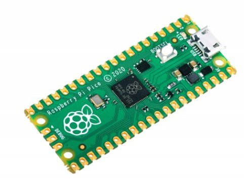
In this post, we are going to discuss the Raspberry Pi Pico development board which is the first development board from the Raspberry Pi in the microcontroller series. It can be programmed with micropython as well as C/C++ SDK. Raspberry Pi Pico is a low-cost, high-performance board based on the Raspberry Pi RP2040 microcontroller chip. RP2040 chip contains a dual-core cortex M0+ microcontroller which can operate up to 133MHz This chip offers 26 multi-function GPIO pins and 2MB of onboard Flash memory.
Recommended Components
The following parts are used in this article, along with a generic electronics kit that is handy for building and testing the circuit.
| Component | How it’s used | Buy on Amazon |
|---|---|---|
| Raspberry Pi Pico board | The RP2040-based Raspberry Pi Pico board this article covers. | Check Price |
| Electronic component assortment kit (1390 pcs) | A handy assortment of resistors, capacitors, LEDs, diodes and transistors for building circuits. | Check Price |
| Digital multimeter (AstroAI) | Measures voltage, current, resistance and checks continuity while you build and debug. | Check Price |
| Breadboard | Solderless base for prototyping the circuit. | Check Price |
| Jumper Wires | Make the connections on the breadboard. | Check Price |
As an Amazon Associate we earn from qualifying purchases. Prices and availability are accurate as of the date/time indicated and are subject to change.
Raspberry Pi Pico Pinout
The following picture shows the pinout diagram of the Raspberry Pi Pico development board. It provides a total of 40 pins including, 26 GPIO pins, eight GND, 3 debugging, and Vcc pins. The color marking at the bottom end of this pinout diagram shows Power, ground, UART, GPIO, PWM, ADC, SPI, I2C, system control, and Debugging pins. It is a 21×51 ‘DIP’ style 1mm thick PCB.

All GPIO pins have multiple functions. For example, GP0 and GP1 pins can be used as digital input, digital output, I2C0 ( SDA and SCK pins), UART0 ( Rx and Tx). But only one alternate function can be used at a time.
Raspberry Pi Pico Peripherals Pinout
Now let’s see the pin configuration details of all peripherals which are supported by the Raspberry Pi Pico development board:
GPIO Pins
Raspberry Pi Pico exposes 26 multi-function GPIO pins from a total of 36 GPIO pins available in RP2040 microcontroller. Out of these 26 pins, 23 pins are digital pins, and only 3 pins have analog read capability. These digital pins are marked as GP0, GP1, and up to GP22. GP23, GP24, and GP25 are not exposed on the pinout. Therefore cannot be used. GP26, GP27, and GP28 are the next digital pins available. These 26 GPIO pins can be used both in digital input and digital output mode.
Learn to use GPIO pins here:
- Raspberry Pi Pico GPIO Programming with MicroPython – LED Blinking Examples
- Interface Push Button with Raspberry Pi Pico and Control LED
GPIO Interrupt Pins
All GPIO pins can be configured as an external interrupt pin on the following four changes on the state of GPIO pins:
- Level high
- Level Low
- Positive edge ( transition from active low to active high)
- Negative edge ( transition from active high to active low)
Note: The Raspberry Pi Pico’s GPIOs are connected to the on-board 3.3V rail and are therefore fixed at 3.3V.
For more details, you can see this example where we used a PIR motion sensor to read its output on interrupt using Raspberry Pi Pico:
RPi Pico ADC Pins
It supports four 12-bit SAR based analog to digital converters. But only three analog channels are exposed to pinout. The fourth analog channel is internal connected to the internal temperature sensor. Therefore, if we want to measure temperature, we can directly use build-in temperature by reading the analog value of ADC4. The following table shows that the input signal for ADC0, ADC1, and ADC2 can be connected with GP26, GP27, and GP28 pins, respectively.
| ADC Module | GPIO Pins |
|---|---|
| ADC0 | GP26 |
| ADC1 | GP27 |
| ADC2 | GP28 |
A/D conversion can be performed in polling, interrupt, and FIFO with DMA mode.
ADC conversion speed per sample is 2μs that is 500kS/s. Because RP2040 microcontroller operates on 48MHZ clock frequency which comes from USB PLL. ADC takes 96 CPU clock cycles to perform one conversion. Therefore, the sampling frequency is
96 x 1 / 48MHz) = 2 μs per sample (500kS/s).
Check this Raspberry Pi Pico ADC tutorial:
I2C Pins
RP2040 chip has two I2C controllers. Both I2C controllers are accessible through GPIO pins of Raspberry Pi Pico. The following table shows the connection of GPIO pins with both I2C controllers. Each connection of the controller can be configured through multiple GPIO pins as shown in the figure. But before using an I2C controller, you should configure in software which GPIO pins you want to use with a specific I2C controller.
| I2C Controller | GPIO Pins |
|---|---|
| I2C0 – SDA | GP0/GP4/GP8/GP12/GP16/GP20 |
| I2C0 – SCL | GP1/GP5/GP9/GP13/GP17/GP21 |
| I2C1 – SDA | GP2/GP6/GP10/GP14/GP18/GP26 |
| I2C1 – SCL | GP3/GP7/GP11/GP15/GP19/GP27 |
I2C controller of RP4020 chip supports the following features:
- Master or Slave Mode ( Default salve address = 0x055)
- Three speed modes such as Standard ( m 0 to 100 Kb/s) , Fast( ess than or equal to 400 Kb/s) and Fast Plus mode ( s less than or equal to 1000 Kb/s)
- Transmit and Recieve Buffers
- Can be used in interrupt and DMA mode
Learn how to use I2C pins:
- Raspberry Pi Pico I2C Communication
- MPU6050 with Raspberry Pi Pico
- BME280 with Raspberry Pi Pico using MicroPython
- I2C LCD Interfacing with Raspberry Pi Pico Display Text and Custom Characters
SPI Pins
RP2040 chip supports two SPI peripherals. Both SPI module pins are accessible through GPIO pins of Raspberry Pi Pico. The following table shows the connection of GPIO pins with both SPI modules. Each connection of SPI controller pins can be configured through multiple GPIO pins as shown in the figure. But before using SPI, you should configure in software which GPIO pins you want to use with a specific SP peripheral.
| SPI Controller | GPIO Pins |
|---|---|
| SPI0_RX | GP0/GP4/GP16 |
| SPI0_TX | GP3/GP7/GP19 |
| SPI0_CLK | GP2/GP6/GP18 |
| SPI0_CSn | GP1/GP5/GP17 |
| SPI1_RX | GP8/GP12/ |
| SPI1_TX | GP11/GP15/ |
| SPI1_CLK | GP10/GP14/ |
| SPI1_CSn | GP9/GP13/ |
Each SPI controller supports master and slave mode and are compatible with the following four modes:
- Motorola SPI Interface
- TI Serial Interface
- National Semiconductor Serial Interface
It has 8 buffers for each transmitter and receiver of the SPI controller. Moreover, it can also be driven with interrupt or DMA.
UART Pins
RP2040 contains two identical UART peripherals with separate 32×8 Tx and 32×12 Rx FIFOs. The following table lists the GPIO pins for both UART peripherals which are exposed on Raspberry Pi Pico development board pinouts.
| UART Pins | GPIO Pins |
|---|---|
| UART0-TX | GP0/GP12/GP16 |
| UART0-RX | GP1/GP13/GP17 |
| UART1-TX | GP4/GP8 |
| UART1-RX | GP5/GP9 |
Some of the prominent features of UART peripherals are:
- Programmable Buad rate generator
- Supports standard asynchronous communication bits such as start, stop and parity bit.
- Programmable hardware serial flow control
In the following example, we have interfaced a GPS module with Raspberry Pi Pico which provides data over UART:
PWM Pins
RP2040 microcontroller contains 8 PWM blocks and each PWM block provides two PWM signals. That means each slice can drive up to two PWM signals. Hence, there is a total of 16 PWM signal output available on Raspberry Pi Pico. All GPIO pins can be configured to get any PWM signal output.
Learn how to generate PWM:
Raspberry Pi Pico Features and Specifications
| Feature | Availability |
|---|---|
| Microcontroller | RP2040 |
| Architecture | Dual-core Arm Cortex M0+ processor |
| Flash | 2MB |
| SRAM | 264KB |
| GPIO Pins | 26 |
| I2C | 2 |
| UART | 2 |
| SPI | 2 |
| PWM | 8 PWM Blocks – 16 Outputs |
| ADC | 3 12-bit ADC |
| State Machines | 8 × Programmable I/O (PIO) state machines |
| DAC | 0 |
| USB | USB 1.1 with device and host support |
| Timer | single 64-bit counter |
| Watchdog | one 32-bit |
| Real time clock | 1- RTC |
Raspberry Pi Pico Programming
Raspberry Pi foundation provided two programming options to write programs for the Raspberry Pi Pico board such as C/C++ SDK and Micropython. They also provide their own SDKs for both C and Micropyhton.
- Pico C/C++ SDK
- Pico Python SDK
- Arduino IDE
We can also program Raspberry Pi Pico using Thonny IDE and support for the Pico board is available in thonny IDE. You can refer to this getting started guide of Thonny MicroPython IDE:
Datasheet
You can refer to the datasheet to explore further:
In the coming tutorials, we will start writing our first program for the RPI Pico development board. Meanwhile, you may like to check these recent projects developed with Raspberry Pi Pico:
Raspberry Pi Pico Limitations
Like ESP32 and ESP8266, Raspberry Pi Pico can be programmed with Micropython. But unlike ESP32 and ESP8266, it doesn’t contain onboard WiFi, Bluetooth, and BLE peripherals. Hence, to use this board for IoT projects, we will have to connect external WiFi, Bluetooth, and BLE modules. It is a great choice for low-cost applications. But adding WiFi, Bluetooth and BLE externally will make its price more than an ESP32 board. This is the first development board in the microcontroller series from Raspberry Pi. Maybe they will add more onboard peripherals in the next versions of the development board.
Tutorials and Projects:
- Getting Started with Raspberry Pi Pico using Thonny IDE
- Getting Started with Raspberry Pi Pico using uPyCraft IDE
- Generate Delay with Raspberry Pi Pico Timers using MicroPython
- OLED Display with Raspberry Pi Pico using MicroPython
- HC-SR04 Ultrasonic Sensor with Raspberry Pi Pico using MicroPython
- DHT11 DHT22 with Raspberry Pi Pico using MicroPython
- DS18B20 Temperature Sensor with Raspberry Pi Pico using MicroPython
- Control DC Motor using L298N Driver with Raspberry Pi Pico and MicroPython
- HC-05 Bluetooth Interfacing with Raspberry Pi Pico – Control Outputs
- Servo Motor with Raspberry Pi Pico using MicroPython
- 28BYJ-48 Stepper Motor with Raspberry Pi Pico using MicroPython
- Interface Analog Joystick Module with Raspberry Pi Pico
- TM1637 4-Digit 7 Segment Display Module with Raspberry Pi Pico
- Data Logger with Raspberry Pi Pico and Micro SD Card
- Interface Micro SD Card Module with Raspberry Pi Pico
- RC522 RFID Reader Module with Raspberry Pi Pico
- Raspberry Pi Pico Dual Core Programming
- MAX7219 LED Dot Matrix Display with Raspberry Pi Pico
- Interface ESP8266 WiFi Module with Raspberry Pi Pico
- Raspberry Pi Pico Web Server with BME280 (Weather Station)
- Raspberry Pi Pico BME680 Web Server with MicroPython
- Raspberry Pi Pico DS18B20 Web Server (Weather Station)
- Raspberry Pi Pico DHT22 Web Server (Weather Station)
- Raspberry Pi Pico Web Server Control GPIO Outputs
- Raspberry Pi Pico Send BME280 Readings to ThingSpeak
- Raspberry Pi Pico Send DHT22/DHT11 Sensor Readings to ThingSpeak
- Raspberry Pi Pico Send DS18B20 Sensor Readings to ThingSpeak
Great info sheet, can you please include details for ADC3 use.