In this tutorial, you will learn how to interface the ESP8266-01 WiFi module with Raspberry Pi Pico to get internet connectivity. We will create a TCP Web Server with Raspberry Pi Pico by using AT commands of the ESP-01 module and use the serial port of the Pico board to configure the ESP-01 WiFi module to connect with WiFi and to create a web server. We will use Thonny IDE to program Raspberry Pi Pico with ESP-01 in MicroPython.
Recommended Components
The following components are used in this project or are helpful for getting started with Raspberry Pi Pico development.
| Component | How it’s used in this project | Buy on Amazon |
|---|---|---|
| Raspberry Pi Pico | The RP2040 microcontroller board configured as the web server. | Check Price |
| ESP8266 ESP-01 Module | Wi-Fi module that gives the Pico internet connectivity over UART. | Check Price |
| Breadboard | Solderless breadboard for wiring the Pico and ESP-01. | Check Price |
| Jumper Wires | Connecting wires for the UART and power connections. | Check Price |
As an Amazon Associate we earn from qualifying purchases. Prices and availability are accurate as of the date/time indicated and are subject to change.
Raspberry Pi Pico is a low-cost, high-performance board based on the Raspberry Pi RP2040 microcontroller chip. But, it does not support WiFi capabilities hence we have to use an external WiFi module to enable WiFi connectivity for Raspberry Pi Pico.
ESP8266 WiFi Module Introduction
In August 2014, Espressif Systems launched their first raw module, which is manufactured by a third-party AI-Thinker. The module is referred to as the ESP-01 module.
ESP8266 delivers a highly integrated WiFi solution that meets the needs of the Internet of Things industries such as low cost, efficient power usage, trustworthy performance, and compact design.
The ESP8266 WIFI module is basically a complete WiFi solution, which has self-contained integrated TCP/IP protocol stack that can be easily connected to the microcontroller for gaining access to any WiFi network. We will use send AT commands to ESP8266 module over UART from Raspberry Pi Pico to configure the TCP Web server.
There are many ESP8266 WiFi modules available in the market ranging from ESP-01 to ESP-12. But in this tutorial, we are using ESP-01. AT commands are the same for all these ESP modules.
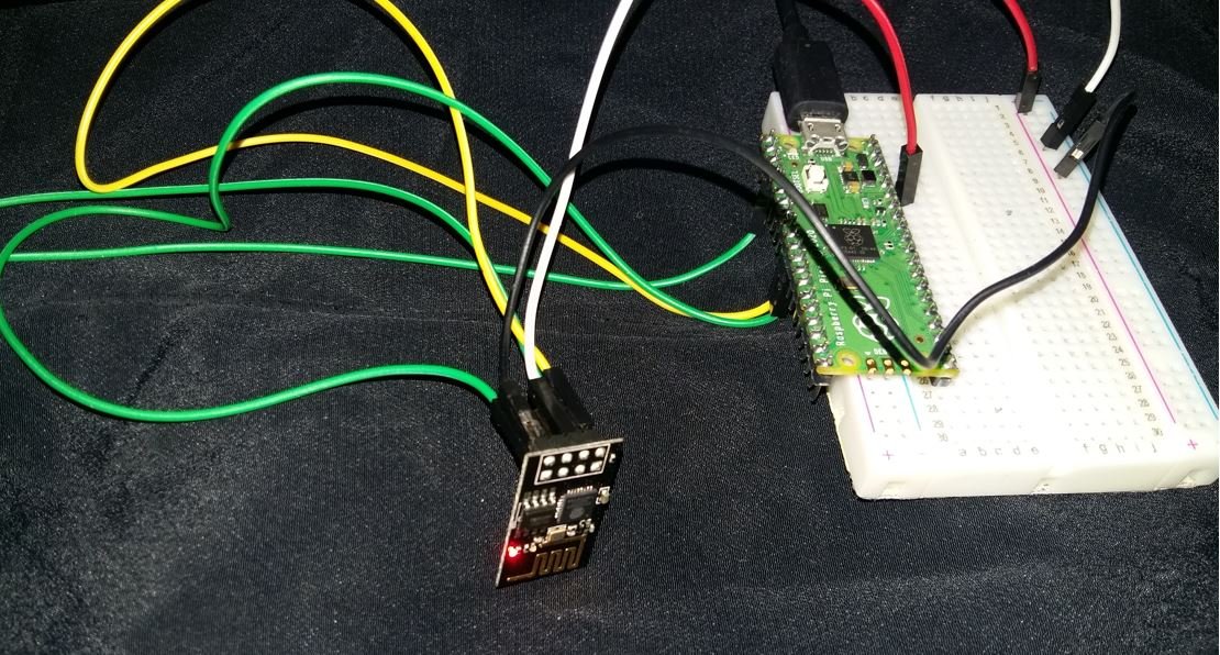
Interfacing ESP8226 Wi-Fi Module with Raspberry Pi Pico
In this section, we will see the pinouts of ESP-01 and Pico board, and then we will see how to connect them to each other to transfer data using AT commands.
ESP-01 Module pinout
The ESP8266-01 WiFi module consists of two rows of eight pins. The pin configuration diagram is shown in the figure below:
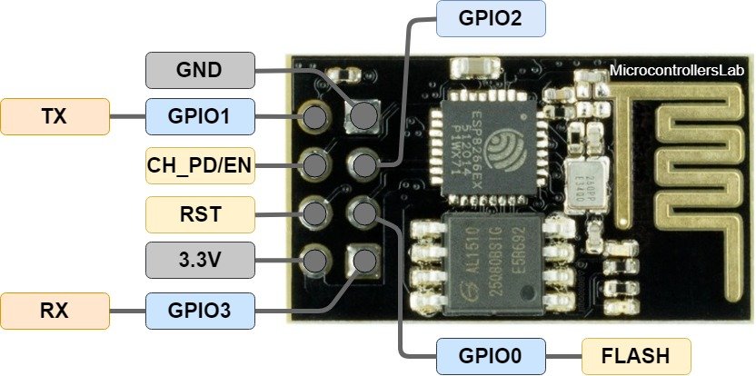
It has a total of 8 pins of which 6 pins are active.
| Label | Description |
|---|---|
| 3.3V | Supply 3.3 volts pin |
| GND | Ground pin |
| RST | Reset Pin |
| CH_PD/EN | Chip Power and Enable pin |
| GPIO 0 to 3 | UART interface and input/output pins |
- Pin_1, which is a GND pin, is directly connected to the ground for power on this module.
- Pins_2 and 3, which are the GPIO 2 and GPIO 0, these pins decide in which mode the module would be a start-up, in other words, these are mode selected pins.
- Pins_4 and 5, which are RX and TX, these pins are used for communication purposes and program the module.
- Pin_6 which is CH_PD, it is called chip power-down pin.
- Pin_7 which is the RST pin and this pin is used to reset module.
- Pin_8 is a VCC pin that is used to power the module. The operating voltage of ESP-01 is 3.3 volts.
Interfacing ESP-01 Wi-Fi Module with Raspberry Pi Pico
We will require the following components:
- Raspberry Pi Pico
- ESP8266 ESP-01 Module
- Connecting Wires
- Breadboard (not necessary)
As we have seen above, the ESP-01 module consists of 8 pins. However, we will use 5 pins to connect it with the Raspberry Pi Pico board. These include the VCC, EN, GND, RX, and TX pins. The RX and TX pins of the module will be connected with the UART pins of the Pi Pico board. Let us first have a look at the Raspberry Pi UART Pins.
Raspberry Pi Pico UART Pins
Raspberry Pi Pico contains two identical UART peripherals with separate 32×8 Tx and 32×12 Rx FIFOs.

The following table lists the GPIO pins for both UART peripherals which are exposed on Raspberry Pi Pico development board pinouts.
| UART Pins | GPIO Pins |
|---|---|
| UART0-TX | GP0/GP12/GP16 |
| UART0-RX | GP1/GP13/GP17 |
| UART1-TX | GP4/GP8 |
| UART1-RX | GP5/GP9 |
Connection Diagram
For this tutorial, we will use UART0 TX and RX pins of Raspberry Pi Pico. Follow the connection diagram below to connect the two devices.
| Raspberry Pi Pico | ESP-01 |
|---|---|
| 3.3V | VCC |
| 3.3V | EN |
| GND | GND |
| GP1 (UART0 RX) | TX |
| GP0 (UART0 TX) | RX |
Raspberry Pi Pico Web Server MicroPython Script
The following MicriPython script of Raspberry Pi Pico sends AT commands to the ESP8266 module to configure ESP8266 as a TCP web server. We will see details of all AT commands in the next sections.
import uos
import machine
import utime
recv_buf="" # receive buffer global variable
print()
print("Machine: \t" + uos.uname()[4])
print("MicroPython: \t" + uos.uname()[3])
uart0 = machine.UART(0, baudrate=115200)
print(uart0)
def Rx_ESP_Data():
recv=bytes()
while uart0.any()>0:
recv+=uart0.read(1)
res=recv.decode('utf-8')
return res
def Connect_WiFi(cmd, uart=uart0, timeout=3000):
print("CMD: " + cmd)
uart.write(cmd)
utime.sleep(7.0)
Wait_ESP_Rsp(uart, timeout)
print()
def Send_AT_Cmd(cmd, uart=uart0, timeout=3000):
print("CMD: " + cmd)
uart.write(cmd)
Wait_ESP_Rsp(uart, timeout)
print()
def Wait_ESP_Rsp(uart=uart0, timeout=3000):
prvMills = utime.ticks_ms()
resp = b""
while (utime.ticks_ms()-prvMills)<timeout:
if uart.any():
resp = b"".join([resp, uart.read(1)])
print("resp:")
try:
print(resp.decode())
except UnicodeError:
print(resp)
Send_AT_Cmd('AT\r\n') #Test AT startup
Send_AT_Cmd('AT+GMR\r\n') #Check version information
Send_AT_Cmd('AT+CIPSERVER=0\r\n') #Check version information
Send_AT_Cmd('AT+RST\r\n') #Check version information
Send_AT_Cmd('AT+RESTORE\r\n') #Restore Factory Default Settings
Send_AT_Cmd('AT+CWMODE?\r\n') #Query the WiFi mode
Send_AT_Cmd('AT+CWMODE=1\r\n') #Set the WiFi mode = Station mode
Send_AT_Cmd('AT+CWMODE?\r\n') #Query the WiFi mode again
#Send_AT_Cmd('AT+CWLAP\r\n', timeout=10000) #List available APs
Connect_WiFi('AT+CWJAP="HUAWEI-u67E","4uF77R2n"\r\n', timeout=5000) #Connect to AP
Send_AT_Cmd('AT+CIFSR\r\n') #Obtain the Local IP Address
utime.sleep(3.0)
Send_AT_Cmd('AT+CIPMUX=1\r\n') #Obtain the Local IP Address
utime.sleep(1.0)
Send_AT_Cmd('AT+CIPSERVER=1,80\r\n') #Obtain the Local IP Address
utime.sleep(1.0)
print ('Starting connection to ESP8266...')
while True:
res =""
res=Rx_ESP_Data()
utime.sleep(2.0)
if '+IPD' in res: # if the buffer contains IPD(a connection), then respond with HTML handshake
id_index = res.find('+IPD')
print("resp:")
print(res)
connection_id = res[id_index+5]
print("connectionId:" + connection_id)
print ('! Incoming connection - sending webpage')
uart0.write('AT+CIPSEND='+connection_id+',200'+'\r\n') #Send a HTTP response then a webpage as bytes the 108 is the amount of bytes you are sending, change this if you change the data sent below
utime.sleep(1.0)
uart0.write('HTTP/1.1 200 OK'+'\r\n')
uart0.write('Content-Type: text/html'+'\r\n')
uart0.write('Connection: close'+'\r\n')
uart0.write(''+'\r\n')
uart0.write('<!DOCTYPE HTML>'+'\r\n')
uart0.write('<html>'+'\r\n')
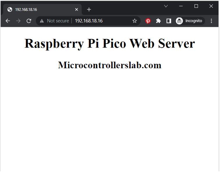
uart0.write('<body><center><h1>Raspberry Pi Pico Web Server</h1></center>'+'\r\n')
uart0.write('<center><h2>Microcontrollerslab.com</h2></center>'+'\r\n')
uart0.write('</body></html>'+'\r\n')
utime.sleep(4.0)
Send_AT_Cmd('AT+CIPCLOSE='+ connection_id+'\r\n') # once file sent, close connection
utime.sleep(2.0)
recv_buf="" #reset buffer
print ('Waiting For connection...')
How does the Code Works?
We will start by importing the machine module and the uos module. Next, we will also import utime module to incorporate delays.
import uos
import machine
import utime
Then, we will print the information about our current operating system in the Thonny shell terminal. We will uos.uname() and print the operating system version and release.
print()
print("Machine: \t" + uos.uname()[4])
print("MicroPython: \t" + uos.uname()[3])
Initialize UART Communication
Then we will create an uart object by using UART() and specify the UART channel as the first parameter and the baud rate as the second parameter. We are using UART0 in this case with baud rate 115200 for the uart communication. ESP8266 has a default baud rate of 115200 hence we will use the same baud rate here for Raspberry Pi Pico UART communication in order to create synchronization. Moreover we will also print the UART details in the shell terminal.
uart0 = machine.UART(0, baudrate=115200)
print(uart0)
This Connect_WiFi() function is used to connect ESP8266 with WiFi.
def Connect_WiFi(cmd, uart=uart0, timeout=3000):
    print("CMD: " + cmd)
    uart.write(cmd)
    utime.sleep(7.0)
    Wait_ESP_Rsp(uart, timeout)
    print()
Next, we will define three functions. The first one is Rx_ESP_Data(). This reads the serial data being received. This data is decoded from UTF-8 format and returned.
def Rx_ESP_Data():
    recv=bytes()
    while uart0.any()>0:
        recv+=uart0.read(1)
    res=recv.decode('utf-8')
    return res
The second function is Send_AT_Cmd(cmd, uart=uart0, timeout=3000). It takes in three parameters, the AT command, the UART channel and the response time. This function will be used to it send an AT command to ESP8266 via uart0. The response time is set to 3 seconds.
def Send_AT_Cmd(cmd, uart=uart0, timeout=3000):
    print("CMD: " + cmd)
    uart.write(cmd)
    Wait_ESP_Rsp(uart, timeout)
    print()
The Wait_ESP_Rsp(uart=uart0, timeout=3000) function waits for 3 seconds to get the response from ESP8266. After receiving the data from ESP8266 it concatenates the received bytes and prints them on the shell terminal.
def Wait_ESP_Rsp(uart=uart0, timeout=3000):
    prvMills = utime.ticks_ms()
    resp = b""
    while (utime.ticks_ms()-prvMills)<timeout:
        if uart.any():
            resp = b"".join([resp, uart.read(1)])
    print("resp:")
    try:
        print(resp.decode())
    except UnicodeError:
        print(resp)
AT Commands
Now let us look at the series of AT commands that we will send through UART0 to ESP8266.
Send_AT_Cmd('AT\r\n')          #Test AT startup
Send_AT_Cmd('AT+GMR\r\n')      #Check version information
Send_AT_Cmd('AT+CIPSERVER=0\r\n')
Send_AT_Cmd('AT+RST\r\n')      #Check version information
Send_AT_Cmd('AT+RESTORE\r\n')  #Restore Factory Default Settings
Send_AT_Cmd('AT+CWMODE?\r\n')  #Query the WiFi mode
Send_AT_Cmd('AT+CWMODE=1\r\n') #Set the WiFi mode = Station mode
Send_AT_Cmd('AT+CWMODE?\r\n')  #Query the WiFi mode again
Send_AT_Cmd('AT+CWJAP="HUAWEI-u67E","4uF77R2n"\r\n', timeout=5000) #Connect to AP
utime.sleep(3.0)
Send_AT_Cmd('AT+CIFSR\r\n')    #Obtain the Local IP Address
utime.sleep(3.0)
Send_AT_Cmd('AT+CIPMUX=1\r\n')
utime.sleep(1.0)
Send_AT_Cmd('AT+CIPSERVER=1,80\r\n')    #Obtain the Local IP Address
utime.sleep(1.0)AT: This type of command is used to test the startup function of WiFi module. The response would be ok, against this command if everything is ok.
Send_AT_Cmd('AT\r\n') #Test AT startupAT+GMR : This type of AT command is used to check the version of AT command and we used SDK version of AT command in this type of WIFI module.
Send_AT_Cmd('AT+GMR\r\n') #Check version informationAT+CIPSERVER=0: This configures the ESP8266 as server and sets the mode as 0 which means delete server (need to follow by restart)
Send_AT_Cmd('AT+CIPSERVER=0\r\n') AT+RST: This type of command is used for reset the WiFi module when it is in working condition. The response would be ok, when reset the module.
Send_AT_Cmd('AT+RST\r\n') AT+RESTORE: This type of command is used to restore factory settings means, when this command is entered then all the parameters are reset automatically to default one’s.
Send_AT_Cmd('AT+RESTORE\r\n') #Restore Factory Default SettingsAT+CWMODE? : This type of command is used to query the WiFi mode of ESP8266.
Send_AT_Cmd('AT+CWMODE?\r\n') #Query the WiFi modeAT+CWMODE=1 : This sets the WiFi mode of ESP8266 in this case in station mode.
Send_AT_Cmd('AT+CWMODE=1\r\n') #Set the WiFi mode = Station modeAT+CWJAP=”SSID”,”PASSWORD”\r\n’, timeout=TIME_ms : This connects the ESP8266 with an AP whose SSID and password are given, The timeout here is the reconnection time.
Connect_WiFi('AT+CWJAP="HUAWEI-u67E","4uF77R2n"\r\n', timeout=5000) #Connect to APAT+CIFSR: This command obtains the local IP address.
Send_AT_Cmd('AT+CIFSR\r\n')AT+CIPMUX=1:This command is used to enable multiple connections (maximum 4)
Send_AT_Cmd('AT+CIPMUX=1\r\n')AT+CIPSERVER=1: This command configures ESP8266 as server.
Send_AT_Cmd('AT+CIPSERVER=1,80\r\n')while loop
Inside the while loop, we will first call Rx_ESP_Data() which returns the data that the ESP8266 receives. This is saved in the variable ‘res.’ Now after a delay of 2 seconds, we will check if the buffer contains an IPD connection or not. If it does then, respond with an HTML handshake.
Print the response in the shell terminal.
res =""
res=Rx_ESP_Data()
print("resp:")
print(res)
Obtain the connection ID and print it.
id_index = res.find('+IPD')
connection_id =  res[id_index+5]
print("connectionId:" + connection_id)
Then by using the uart object on the write() method, we will send the bytes to the UART. First, we are writing the AT command: AT+CIPSEND=’ID’, ‘LENGTH’ This will set the length of the data that will be sent. Next after a delay of 1 second, we will write the HTML body that will build the web page to the serial port. After that, we will close the multiple connections as we are sending the AT command: AT+CIPCLOSE=’ID’. Then we will reset the buffer and wait for the connection.
print ('! Incoming connection - sending webpage')
        uart0.write('AT+CIPSEND='+connection_id+',200'+'\r\n')  #Send a HTTP response then a webpage as bytes the 108 is the amount of bytes you are sending, change this if you change the data sent below
        utime.sleep(1.0)
        uart0.write('HTTP/1.1 200 OK'+'\r\n')
        uart0.write('Content-Type: text/html'+'\r\n')
        uart0.write('Connection: close'+'\r\n')
        uart0.write(''+'\r\n')
        uart0.write('<!DOCTYPE HTML>'+'\r\n')
        uart0.write('<html>'+'\r\n')
        uart0.write('<body><center><h1>Raspberry Pi Pico Web Server</h1></center>'+'\r\n')
        uart0.write('<center><h2>Microcontrollerslab.com</h2></center>'+'\r\n')
        uart0.write('</body></html>'+'\r\n')
        utime.sleep(4.0)
        Send_AT_Cmd('AT+CIPCLOSE='+ connection_id+'\r\n') # once file sent, close connection
        utime.sleep(2.0)
        recv_buf="" #reset buffer
        print ('Waiting For connection...')
Testing Raspberry Pi Pico and ESP8266 Communication
To test the MicroPython script, upload the main.py file to your board and get an IP address to access the web server:

In the shell terminal of your IDE, you will be able to view the following messages:
Now go to the web browser of your system and search with the IP address that was displayed in the shell terminal. The web page will open up.
In summary:
In this tutorial, we have learned how to create a web server using ESP8266 Wi-Fi Module and Raspberry Pi Pico! This step-by-step guide demonstrates the interfacing of ESP8266 with the Raspberry Pi Pico to build a powerful web server. We have also explored the possibilities of controlling devices over Wi-Fi and accessing data remotely with this comprehensive tutorial.
You may also like to read:
- MAX7219 LED Dot Matrix Display with Raspberry Pi Pico
- Raspberry Pi Pico I2C Communication
- Interface Analog Joystick Module with Raspberry Pi Pico
- TM1637 4-Digit 7 Segment Display Module with Raspberry Pi Pico
- Data Logger with Raspberry Pi Pico and Micro SD Card
- Interface Micro SD Card Module with Raspberry Pi Pico
- RC522 RFID Reader Module with Raspberry Pi Pico
Thanks for a detailed tutorial.
I have one problem and that is the return data from the ESP8266 is never decoded properly.
When it comes to “starting connection…” the program crashes with a UnicodeError (this is also when the decode errors are not caught in a try/except statement.
Any tips on how to proceed?
Can bad soldering cause this?
This seems to be a connection issue with Rx and Tx pins of ESP8266 and Raspberry Pi Pico.
Hi,
Perhaps your Pico has bits=16 setting for UART as default. (As it was for mine.)
Maybe it worth to try to give detailed parameters for UART ie:
uart0 = machine.UART(0, bits=8, parity=None, baudrate=115200, tx=machine.Pin(0), rx=machine.Pin(1))
Hello,
Your tutorial was really helpful for me despite first time I got confused answers from ESP.
The modification which made things work was detailed parameters to uart:
uart0 = machine.UART(0, bits=8, parity=None, baudrate=115200, tx=machine.Pin(16), rx=machine.Pin(17))
Parity ans bits setting was different by default on my Pico and I used GPIO16-17 for connection to ESP.
Thanks for your input, we will add this to our article because it may help others too.
Thank you for this code example, very accessible and formative. I was able to get it working after a simple copy-paste. (just change ssid password).(ESP-12S) The test web page is displayed on my pc’s chrome. The only problem is that the web connection does not seem to close correctly with the AT+CIPCLOSE command. The sketch hangs at “waiting for connection” and no longer detects incoming connections. Thank you for your help. Regards Patrice
good morning, how can I add more lines to the web page, I want to add more text but when I add more html code by uart0.write it does not appear in the browser.
Hi,
sounds familiar. Check your CIPSEND-statement !!!! Did you increase the length value?
For some reason it can’t be bigger than 2000????\
Good luck
gr8 post! Your code works perfectly with Waveshare Pico-ESP8266
I’m just starting my adventure with Pi Pico – I wish there were more posts like this