In this tutorial, we will learn to interface MAX7219 LED Dot matrix display with Raspberry Pi Pico. Firstly, we will look into the introduction, pinout of MAX7219 LED dot matrix display module. It is an LED array used to display various types of texts, symbols, and images in the form of dots which consists of LEDs. Through this tutorial, we will familiarize you with the MAX7219 dot matrix display and program Raspberry Pi Pico to show various demonstrations of displaying texts. These will include displaying and scrolling text on the dot matrix.
Recommended Components
The following components are used in this project or are helpful for getting started with Raspberry Pi Pico development.
| Component | How it’s used in this project | Buy on Amazon |
|---|---|---|
| Raspberry Pi Pico | The RP2040 microcontroller board driving the display over SPI. | Check Price |
| MAX7219 LED Dot Matrix Module | 8×8 LED matrix display module used to show and scroll text. | Check Price |
| Jumper Wires | Connecting wires for the SPI and power connections. | Check Price |
As an Amazon Associate we earn from qualifying purchases. Prices and availability are accurate as of the date/time indicated and are subject to change.
MAX7219 LED Dot Matrix Display
MAX7219 LED Dot matrix display is one of the popular ones available in the market and used by students, electronics hobbyists, and especially in industrial display applications. There are two types of modules generally available. These are the FC-16 module and the generic module.
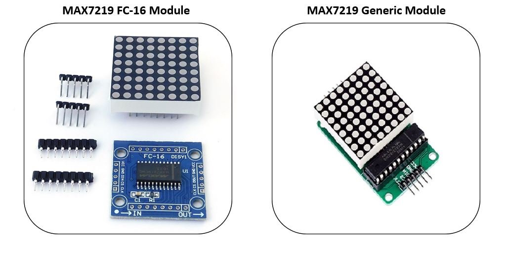
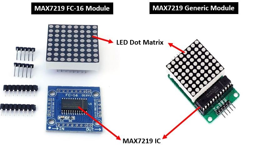
Each module consists of two units. One is the 8X8 LED dot matrix and the other is the MAX7219 IC.
You can find more information about MAX7219 here:
LED Dot Matrix
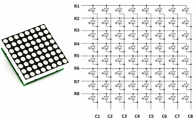
LED dot matrices are available in various dimensions (7×5,8×8, 7×15, etc). The typical 8×8 LED matrix is shown below which comprises of 64 LEDs, 8 for each row and column. Each LED is addressed by its row and column number. Each LED is referred to as a dot.
For making an 8×8 dot matrix all the anodes terminals are connected together in rows R1 to R8, similarly, the cathodes are connected together in columns C1 to C8. The reason for connecting all rows and columns together is to save the required number of pins to control each LED dot. By doing this, the required number of I/O pins has been reduced to 16. Otherwise, we will need 64 pins to control an 8×8 LED matrix. This method of controlling a large number of LEDs with few pins is known as multiplexing.
To Turn on a specific do, we need to apply a positive voltage to the respective row of that dot and negative or ground to the respective column of that dot. If the row gets positive voltage and the column gets negative then only a particular LED will glow.
For example, If you want to glow an LED connected between R2 and C1, we have to apply 00000010 logic on row R2 and 11111110 on column C1. If R5 is pulled high and C4 pulled low, then the LED in the fifth row and the fourth column would be high. Similar logic can also be applied to other rows and columns to turn on and off each row and column LED. Furthermore, to display text on the dot matrix, we control each LED very fast speed that the human eye feels like LEDs are constantly on.
MAX7219 IC
MAX7219 is a common-cathode display driver IC with serial inputs and output pins. It has an adjustable current capability which can be set using only one external resistor. In addition to that, it has a four-wire serial interface that can be easily connected to all microprocessors. It can drive 64 individual LEDs connected at its output pins using only 4 wires by using Raspberry Pi Pico board. Furthermore, it can drive dot matrix displays, 7-Segments displays, and bar graphs.
On top of that, MAX7219 has a built-in BCD decoder that makes it easy to use with seven segment numeric displays. Additionally, it has an 8×8 static RAM that we can use to store numbers. It is one of the most popular displays driver IC.
Some key features of MAX7219 include:
- It is an LED driver display IC with a 10MHz serial interface which allows the user to select the decode/No-Decode digit.
- Its operation is specified in a voltage range of +4.0 to +5.5V. Normally, the voltage supply of +5V is used.
- It provides a feature of digital and analog brightness intensity control and a 150µA shutdown mode in which the current of all segments is pulled to ground.
- It consumes very low power.
- The data is displayed on segments with a delay time of 2.2ms.
- MAX7219 works well in a temperature range of 0°C to +70°C.
- The maximum current for each segment pin is 100mA and for each DIGIT ground pin is 500mA
MAX7219 Dot Matrix Module Pinout
The MAX7219 module has 5 terminals consisting of SPI and power supply terminals. Both types of modules have the same connections on two sides. On one side are the input connections and on the other side are the output connections Below you can view the pinout of the generic module.
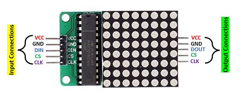
Input Connections
The input connections of the LED matrix are connected with Raspberry Pi Pico
- VCC: This pin supplies power to the MAX7219 module. It is connected with 5V pin of Raspberry Pi Pico.
- GND: This is the ground pin which should be connected with the ground pin of Raspberry Pi Pico.
- DIN: This is the data in pin. It is used as the SPI input to the module.
- CS: This is the Chip Select pin for SPI communication.
- CLK: This is called the ‘Serial Clock’ pin which is used in SPI serial clock output.
Output Connections
The output connections of the LED matrix are connected with the next module if there is a need to attach more units.
- VCC: It is connected to VCC (5V) on the next module
- GND: It is connected to the GND on the next module
- DOUT: This is the Data out pin. It is connected to DIN pin of the next module.
- CS: This is connected to the CS pin of the next module
- CLK: This is connected to the CLK pin of the next module
MAX7219 LED Dot Matrix Module Interfacing with Raspberry Pi Pico
Following components are required:
- Raspberry Pi Pico
- MAX7219 module
- Connecting Wires
For this project, we will be using the FC-16 module consisting of four units.

Now, we will show you how to connect the MAX7219 module and Raspberry Pi Pico together.
The SPI communication helps to communicate with MAX7219 module, which is common in every microcontroller. Thus, we will use the SPI interface of Raspberry Pi Pico. Let us first learn about the Raspberry Pi Pico SPI interface.
Raspberry Pi Pico SPI Pins
Raspberry Pi Pico supports two SPI peripherals. Both SPI module pins are accessible through GPIO pins of Raspberry Pi Pico. The following table shows the connection of GPIO pins with both SPI modules. Each connection of SPI controller pins can be configured through multiple GPIO pins as shown in the figure. But before using SPI, you should configure in software which GPIO pins you want to use with a specific SP peripheral.
| SPI Controller | GPIO Pins |
| SPI0_RX | GP0/GP4/GP16 |
| SPI0_TX | GP3/GP7/GP19 |
| SPI0_SCK | GP2/GP6/GP18 |
| SPI0_CSn | GP1/GP5/GP17 |
| SPI1_RX | GP8/GP12 |
| SPI1_TX | GP11/GP15 |
| SPI1_SCK | GP10/GP14 |
| SPI1_CSn | GP9/GP13 |
The figure below shows the SPI pins of Raspberry Pi Pico.

The table below shows the connections between the devices that we will use in our project.
Raspberry Pi Pico with MAX7219 LED Dot Matrix Display Module
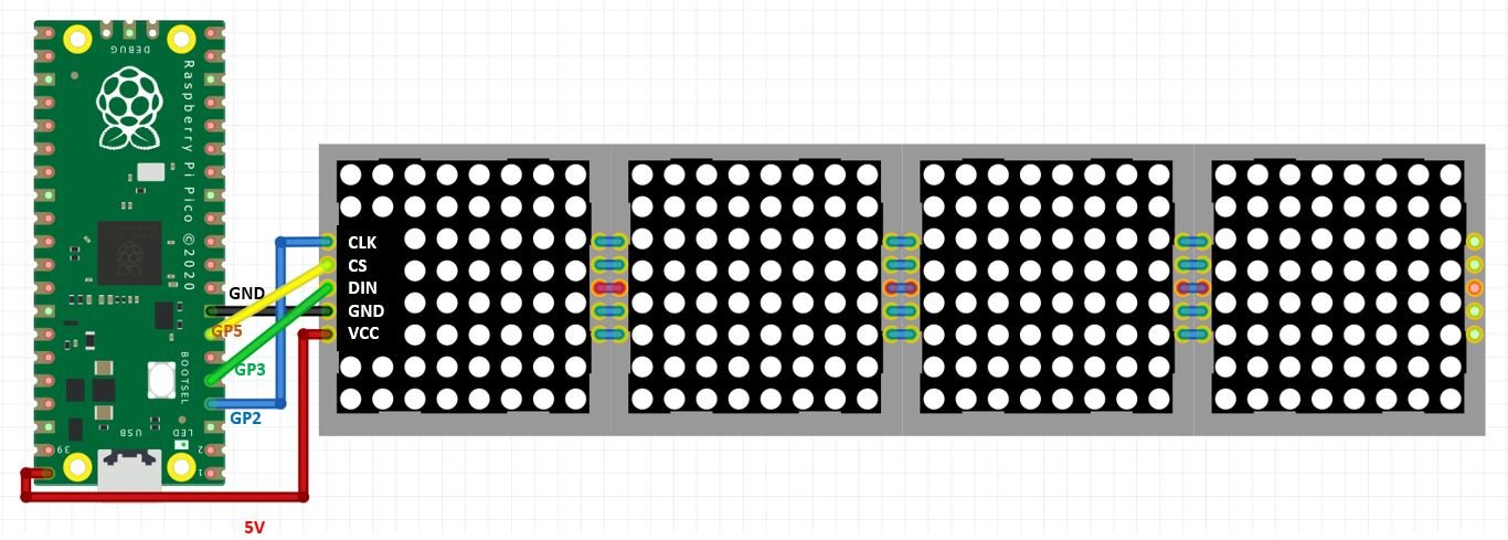
Now let us see how to connect the MAX7219 module and the Raspberry Pi Pico board. The table below shows the connections between the two devices:
| MAX7219 Module | Raspberry Pi Pico |
|---|---|
| VCC | VBUS (5V) |
| GND | GND |
| DIN | GP3 (SPI0_TX) |
| CS | GP5 (SPI0_CSn) |
| CLK | GP2 (SPI0_SCK) |
As shown from the table, we will connect the VCC terminal of the MAX7219 module with the 5V pin of Raspberry Pi Pico. Both grounds will be common. The SPI GPIO pins of Raspberry Pi Pico are being used to connect with each of the remaining SPI terminals of the MAX7219 module. You can use other Raspberry Pi Pico SPI pins as well.
Installing MAX7219 MicroPython Library
We will use Thonny IDE to program our Raspberry Pi Pico. Make sure you have the latest version of the IDE installed in your system. For this project we will require the MicroPython max7219 library. Copy this library and save it in your Raspberry Pi Pico with the respective file name (max7219.py) from the GitHub link.
Open a new file in Thonny. Copy the library given below or from the link given above. Save it to Raspberry Pi Pico with the name max7219.py under the lib folder.
max7219.py
"""
MicroPython max7219 cascadable 8x8 LED matrix driver
https://github.com/mcauser/micropython-max7219
MIT License
Copyright (c) 2017 Mike Causer
Permission is hereby granted, free of charge, to any person obtaining a copy
of this software and associated documentation files (the "Software"), to deal
in the Software without restriction, including without limitation the rights
to use, copy, modify, merge, publish, distribute, sublicense, and/or sell
copies of the Software, and to permit persons to whom the Software is
furnished to do so, subject to the following conditions:
The above copyright notice and this permission notice shall be included in all
copies or substantial portions of the Software.
THE SOFTWARE IS PROVIDED "AS IS", WITHOUT WARRANTY OF ANY KIND, EXPRESS OR
IMPLIED, INCLUDING BUT NOT LIMITED TO THE WARRANTIES OF MERCHANTABILITY,
FITNESS FOR A PARTICULAR PURPOSE AND NONINFRINGEMENT. IN NO EVENT SHALL THE
AUTHORS OR COPYRIGHT HOLDERS BE LIABLE FOR ANY CLAIM, DAMAGES OR OTHER
LIABILITY, WHETHER IN AN ACTION OF CONTRACT, TORT OR OTHERWISE, ARISING FROM,
OUT OF OR IN CONNECTION WITH THE SOFTWARE OR THE USE OR OTHER DEALINGS IN THE
SOFTWARE.
"""

from micropython import const
import framebuf

_NOOP = const(0)
_DIGIT0 = const(1)
_DECODEMODE = const(9)
_INTENSITY = const(10)
_SCANLIMIT = const(11)
_SHUTDOWN = const(12)
_DISPLAYTEST = const(15)

class Matrix8x8:
    def __init__(self, spi, cs, num):
        """
        Driver for cascading MAX7219 8x8 LED matrices.
        >>> import max7219
        >>> from machine import Pin, SPI
        >>> spi = SPI(1)
        >>> display = max7219.Matrix8x8(spi, Pin('X5'), 4)
        >>> display.text('1234',0,0,1)
        >>> display.show()
        """
        self.spi = spi
        self.cs = cs
        self.cs.init(cs.OUT, True)
        self.buffer = bytearray(8 * num)
        self.num = num
        fb = framebuf.FrameBuffer(self.buffer, 8 * num, 8, framebuf.MONO_HLSB)
        self.framebuf = fb
        # Provide methods for accessing FrameBuffer graphics primitives. This is a workround
        # because inheritance from a native class is currently unsupported.
        # http://docs.micropython.org/en/latest/pyboard/library/framebuf.html
        self.fill = fb.fill  # (col)
        self.pixel = fb.pixel # (x, y[, c])
        self.hline = fb.hline  # (x, y, w, col)
        self.vline = fb.vline  # (x, y, h, col)
        self.line = fb.line  # (x1, y1, x2, y2, col)
        self.rect = fb.rect  # (x, y, w, h, col)
        self.fill_rect = fb.fill_rect  # (x, y, w, h, col)
        self.text = fb.text  # (string, x, y, col=1)
        self.scroll = fb.scroll  # (dx, dy)
        self.blit = fb.blit  # (fbuf, x, y[, key])
        self.init()

    def _write(self, command, data):
        self.cs(0)
        for m in range(self.num):
            self.spi.write(bytearray([command, data]))
        self.cs(1)

    def init(self):
        for command, data in (
            (_SHUTDOWN, 0),
            (_DISPLAYTEST, 0),
            (_SCANLIMIT, 7),
            (_DECODEMODE, 0),
            (_SHUTDOWN, 1),
        ):
            self._write(command, data)

    def brightness(self, value):
        if not 0 <= value <= 15:
            raise ValueError("Brightness out of range")
        self._write(_INTENSITY, value)

    def show(self):
        for y in range(8):
            self.cs(0)
            for m in range(self.num):
                self.spi.write(bytearray([_DIGIT0 + y, self.buffer[(y * self.num) + m]]))
            self.cs(1)
Raspberry Pi Pico with MAX7219 LED Matrix: MicroPython Sketches
In this section, we will show you how to use MAX7219 LED matrix with two sketches. We will be able to print various texts on the LED matrix. Additionally, we will also scroll a simple text from right to left.
MAX7219 Dot Matrix displaying texts
Open your Thonny IDE and go to File > New. Copy the code below in that file. This sketch will display a three different texts on the LED matrix after a delay of 1 second.
from machine import Pin, SPI
import max7219
from time import sleep

spi = SPI(0,sck=Pin(2),mosi=Pin(3))
cs = Pin(5, Pin.OUT)

display = max7219.Matrix8x8(spi, cs, 4)

display.brightness(10)

while True:

    display.fill(0)
    display.text('PICO',0,0,1)
    display.show()
    sleep(1)

    display.fill(0)
    display.text('1234',0,0,1)
    display.show()
    sleep(1)

    display.fill(0)
    display.text('done',0,0,1)
    display.show()
    sleep(1)
How the Code Works?
In this part we will discuss how the code works.
Importing Libraries
We will import the library for the Pin class and the SPI class from the machine module. To interact with the input/output GPIOs we will import the machine module that contains classes to interact with the GPIOs. We should also import the sleep module to insert delay in our MicroPython script. Moreover, we will import the max7219 library as well to work with the LED display.
from machine import Pin, SPI
import max7219
from time import sleep
Initializing SPI
The next step is to initialize the SPI interface with the required parameters including the SPI channel number and SPI pins by creating an object ‘spi’. By using SPI() we specified the SPI channel number as the first parameter and the SPI pins sck and mosi as the rest of the parameters.
spi = SPI(0,sck=Pin(2),mosi=Pin(3))
Next we will configure the GPIO pin connected with the CS pin of the module as an output pin. The first argument in the Pin() class is the pin number on which we are configuring the output. The output is on GP5 which is connected to CS. The second argument shows the pin mode e.g. digital input or digital output mode. As we are configuring GP5 as the digital output we gave it as ‘Pin.Out’. This is stored in the object ‘cs’.
cs = Pin(5, Pin.OUT)Then we will create the matrix ‘display’ object and specify 4 devices.
display = max7219.Matrix8x8(spi, cs, 4)We will set the brightness of the display by using the brightness() method on the display object. This takes in a parameter from 1-15 where 15 is the highest level of brightness.
display.brightness(10)Display Text
We will continuously change the text after every 1 second. First we will display “PICO” then the numbers “1234” and then “done.”
while True:

    display.fill(0)
    display.text('PICO',0,0,1)
    display.show()
    sleep(1)

    display.fill(0)
    display.text('1234',0,0,1)
    display.show()
    sleep(1)

    display.fill(0)
    display.text('done',0,0,1)
    display.show()
    sleep(1)
Using fill() method on the display object and passing 0 as a parameter inside it, we will first clear the display.
First we will display the text ‘PICO’ for 1 second. This will be achieved by using text() and passing the string as the first parameter, x as the second parameter, y as the third parameter and col=1 as the last parameter. The show() method will display the string on the LED display.
    display.fill(0)
    display.text('PICO',0,0,1)
    display.show()
    sleep(1)
Likewise, we will display the numbers ‘1234’ and the text ‘done’ after that.


    display.fill(0)
    display.text('1234',0,0,1)
    display.show()
    sleep(1)

    display.fill(0)
    display.text('done',0,0,1)
    display.show()
    sleep(1)
Demonstration
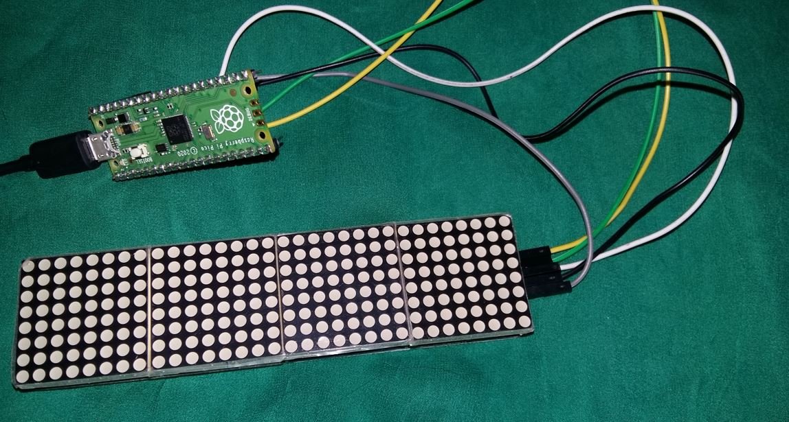
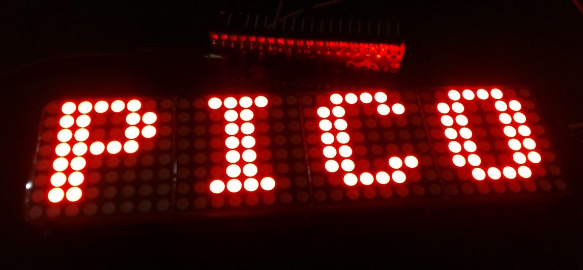
To see the demonstration of the above code, upload the code to Raspberry Pi Pico.
Once the code is uploaded, the LED matrix will start displaying the texts. Watch the video below:
MAX7219 Dot Matrix MicroPython Sketch: Scrolling Text
Open your Thonny IDE and go to File > New. Copy the code below in that file. This sketch will scroll a text from right to left at a set speed.
from machine import Pin, SPI
import max7219
from time import sleep

spi = SPI(0,sck=Pin(2),mosi=Pin(3))
cs = Pin(5, Pin.OUT)

display = max7219.Matrix8x8(spi,cs,4)

display.brightness(10)

scrolling_message = "SCROLLING"
length = len(scrolling_message)
column = (length * 8)

display.fill(0)
display.show()
sleep(1)

while True:
    for x in range(32, -column, -1):
        display.fill(0)
        display.text(scrolling_message ,x,0,1)
        display.show()
        sleep(0.1)
How does Code Works?
We will discuss the parts where we are incorporating the scrolling feature. Rest of the code is similar to the one which we discussed above.
After initializing the SPI interface, setting its brightness and clearing the display we will create a variable to hold the text that we want to scroll. In our case, it is ‘SCROLLING.’ This is saved in the variable ‘scrolling_message.’
scrolling_message = "SCROLLING"Next, find the length of the text.
length = len(scrolling_message)Additionally, calculate the columns for the scrolling text. This is found by multiplying the length of the text with 8.
column = (length * 8)Inside the infinite while loop, we will use a for statement to scroll the text. First we clear the LED display. Then we use text() method on the display object and write the scrolling text in to frame buffer. Then we display the text using the show() method on the display object. To set the speed of the scrolling text we add a delay of 100 milliseconds using the sleep() method.
while True:
    for x in range(32, -column, -1):
        display.fill(0)
        display.text(scrolling_message ,x,0,1)
        display.show()
        sleep(0.1)
Demonstration
To see the demonstration of the above code, upload the code to Raspberry Pi Pico.
Once the code is uploaded to the board, the SCROLLING text will start scrolling towards the left side. This will happen continuously.
Conclusion
In conclusion, we have learned to interface MAX7219 dot LED matrix display module with Raspberry Pi Pico. We looked at two MicroPython sketches. These sketches familiarized us with displaying plain text on the display and also scrolling it at a set speed.
You may also prefer to study other examples on MAX7219:
- 8×8 LED Matrix Interfacing with MAX7219 and Pic Microcontroller
- LED Dot Matrix Display with ESP32 and MAX7219
- MAX7219 Interfacing with 8-digit 7 Segment Display and PIC16F877A
- MAX7219 LED Dot Matrix Display with ESP8266 NodeMCU
- Internet Based Digital Clock using ESP32 and MAX7219 Dot Matrix Display
- MAX7219 LED Dot Matrix Display Interfacing with Arduino
Please how do I get those components
Hello, how to change font file?
Hello, do you know how to change the font?
in the circuitpython doc it is writing that we could add a font_name as parameter to .text() but it does not work.
i’m certainly do in the wrong way but which?
the default font8_5.bin have no diacritics chars..
How to make a .bin custopm font.
there is a doc on adafruit’s site to make .otf to .bdf and bdf to pcf file but nothing to bin file.
Any Idea?