In this tutorial, you will learn how to interface the MAX7219 8-digit 7-segment controller IC with PIC Microcontroller. MAX7219 has a built-in circuit to control 8 seven-segment displays. Firstly, it communicates with microcontrollers over SPI communication. Hence, only three pins are required to control 8 seven-segment displays. Secondly, we can use MAX7219 to control dot matrix displays also.
MAX7221 is an equivalent display driver IC. But the only difference is that MAX7221 has low slew-rate and compatible with full SPI communication mode.
Recommended Components
The following components are used in this project or are helpful for building it with a PIC microcontroller.
| Component | How it’s used in this project | Buy on Amazon |
|---|---|---|
| PIC16F877A microcontroller | Host MCU that sends digits to the MAX7219 display driver. | Check Price |
| PICkit 5 programmer/debugger | Flashes the compiled firmware onto the PIC and debugs it. | Check Price |
| MAX7219 8-digit 7-segment display module | 8-digit 7-segment module driven by the MAX7219 in this project. | Check Price |
| Breadboard | Solderless base for wiring the PIC to the display module. | Check Price |
| Jumper Wires | Connect the data, clock and load lines between parts. | Check Price |
As an Amazon Associate we earn from qualifying purchases. Prices and availability are accurate as of the date/time indicated and are subject to change.
MAX7219 Display Driver IC Introduction
Unlike the 74HC595 shift register, we don’t need to control each digit of 7-segment display individually by adding delay. We just send data 7-segments and seven-segment control data. It has a built-in BCD to 7-segment decoder. Most importantly, it has on-chip 8×8 RAM which we can use to store display codes of digits that we want to display.
One of the major advantages of this display driver is that we can update individual bits without updating the entire display that isn’t possible with 74HC595 shift register. Hence, we can save microcontroller execution time and energy.
Moreover, it has a built-in brightness control circuit and by using a scan limit register we can configure the number of digits display we want to use.
Pinout Diagram
As you can depict from this pinout diagram that it is a 24 pin IC. Eight pins provide data to segments that A-G pins. DIG0 to DIG7 pins are used to connect with common pins of 8 common-cathode type seven-segment displays. The pin configuration is the same for both MAX7219 and MAX7212.

This table shows the function of each pin. Out of 14 pins, 16 pins are used to connect 8-digit LED displays.

According to the above table, MAX7219/MAX7212 receives and transmits data through SPI communication. Pin1 (DIN) is a serial data input pin. We connect DIN of MAX7219 with a DOUT pin of PIC16F877A microcontroller SPI pin. Serial data transfer to an internal 16-bit register on every positive edge clock on pin13(Clk). We provide clock signals from Pic microcontroller SPI communication clock pin (SCK).
Recommend Reading: SPI Communication Using Pic microcontroller
MAX7219/MAX7212 Registers
This block diagram shows the configuration registers of MAX7219 LED driver IC. It has drivers for segements and digits.

Following are the main registers that used to configure and control display.
Shutdown Register
When we initially power-up, all control registers go into reset mode. The display will not print anything. It is also used to shut down or activate the display. The address of this register is 0xXC. Writing 0x00 to this register will shut down the IC and if you want to activate it again, write 0x01 through SPI communication. For instance;
SPI1_write(0x0c); //Select shutdown-register
SPI1_write(0x00); //select shutdown mode
SPI1_write(0x00); //select normal operation
Decode-Mode Register (0x09)
It is used to select the number of seven-segments digits we want to use. We can also select either BCD code operation or no-decode operation. But if you want to use 7-segment displays, you should select BCD decode mode. Its address is 0x09. We can select BCD coded format for 1-digit, 4-digit or 8-digit displays by setting this register values to 0x01, 0x0F, and 0XFF respectively.
SPI1_write(0x09); //select decode-Register
SPI1_write(0x01); //set 1-digit BCD display only
SPI1_write(0x0F); //select low-nibble BCD 4-digit 7-segment
SPI1_write(0xFF);  //select all BCD 8-digits
Intensity Register Format (Address = 0xXA)
MAX7219 display driver IC also provides brightness control feature to save power. You can easily control brightness by connecting an external resistor between Iset pin and Vdd pin. Further, you can also adjust intensity by setting values of this register between 0-15 like this:
SPI1_write(0xXA); // Select intensity adjustment mode
SPI1_write(0x00); // intensity or brightness level 0
SPI1_write(0x01); // intensity or brightness level 1
SPI1_write(0x02); // intensity or brightness level 2
SPI1_write(0xXF); // intensity or brightness level 15
Scan-limit Register (Address = 0xXB)
You can select the number of digits display (1-8) with scan-limit register. As you know that 7-segment displays are usually multiplexed to display numbers. Similarly, MAX7219 performs scanning only to the number of segments that you want to use. The scan rate of this display driver is 800Hz with 8 digits displayed. To select number of digits, first send address of scan-limiter and after that send number of digits like this:
SPI1_write(0xXB); // address of scan-limiter
SPI1_write(0x07); // that means we want to display data on all 8-digits
Display-Test Register (Address = 0xXF)
It is used to test the IC. For example, if you are working with this IC and you want to check either something is wrong with your code or MAX7221 is faulty. We can test MAX7219 easily with this display-tester. It can test IC in two modes such as display test and normal operation. In a display test operation, it turns on all LEDs
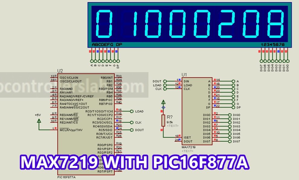
MAX7219/MAX7221 Interfacing Schematic Diagram
For demonstration purposes, we will use all 8 seven-segments with PIC16F877A microcontroller. This circuit diagram shows the MAX7219 interfacing with 8-digit Seven-Segment Display using pic microcontroller.
In this tutorial, we used SPI communication pins of PIC16F877A microcontroller to send data and to provide a clock to MAX7219. We also connect the RC2 pin with the LOAD pin of the display driver. After transferring data, load pin load_pin acknowledges that the data has been loaded and ready to reflect on output pins. Make connections between PIC16F877A and MAX7219 according to this table.
| PIC16F877A | MAX7219/MAX7221 |
|---|---|
| RC0 | LOAD |
| RC3/SCK | CLK |
| RC5/SDO | DIN |
As we mentioned earlier, this LED display driver IC supports a common cathode type display. But we can use it with common-anode type displays also by using PNP transistor with individual digits control pins. Interfacing between MAX7219 and the 8-digit 7-segment device is easy and straightforward.
MAX7219 MikroC Code
This MikroC code controls MAX7219 and prints the data 8-digit device. Make sure to select the frequency of 8MHz while creating a project in the MikroC compiler.
This code is written using MikroC for Pic compiler. Create a new project with MikroC compiler by selecting PIC16F877A microcontroller and set frequency to 8MHz. If you don’t know how create new project in mikroC, we suggest you read this post:
//------------------------------------------------------------------------------
#define DECODE_MODE_REG     0x09
#define INTESITY_REG        0x0A
#define SCAN_LIMIT_REG      0x0B
#define SHUTDOWN_REG        0x0C
#define DISPLAY_TEST_REG    0x0F
//------------------------------------------------------------------------------
#define DISABLE_DECODE      0x00
#define DECODE_ALL          0xFF
#define BRIGHTNESS          0x0F
#define SCAN_LOW_NIBBLE     0x03
#define SCAN_ALL_DIGITS     0x07
#define SHUTDOWN_MODE       0x00
#define NORMAL_OPERATION    0x01
#define DISABLE_TEST_MODE   0x00
#define ENABLE_TEST_MODE    0x01
//------------------------------------------------------------------------------
sbit MAX7219_CS_LOAD at RC0_bit;
sbit MAX7219_CS_LOAD_DIRECTION at TRISC0_bit;
void MAX7219_write(char reg1, char data1)
{
  MAX7219_CS_LOAD  = 0;

  SPI1_write(reg1);
  SPI1_write(data1);

  MAX7219_CS_LOAD  = 1;
}
void MAX7219_init()
{
  SPI1_init();

  MAX7219_write(DECODE_MODE_REG,DECODE_ALL);
  MAX7219_write(INTESITY_REG,BRIGHTNESS);
  MAX7219_write(SCAN_LIMIT_REG,SCAN_ALL_DIGITS);
  MAX7219_write(SHUTDOWN_REG,NORMAL_OPERATION);
  MAX7219_write(DISPLAY_TEST_REG,ENABLE_TEST_MODE);
  MAX7219_write(DISPLAY_TEST_REG,DISABLE_TEST_MODE);
}
void Max7219Print(unsigned long Number, unsigned short NumberOfDigits)
{
  long i;
  for(i=1;Number>0||i-NumberOfDigits<=0;Number/=10,i++)
  {
    MAX7219_CS_LOAD=0;
    SPI1_write(i);
    SPI1_write(Number%10);
    MAX7219_CS_LOAD=1;
  }
}

void Max7219DisplayOff()
{
  MAX7219_CS_LOAD=0;
  SPI1_write(SHUTDOWN_REG);
  SPI1_write(DISABLE_DECODE);
  MAX7219_CS_LOAD=1;
}

void Max7219DisplayOn()
{
  MAX7219_CS_LOAD=0;
  SPI1_write(SHUTDOWN_REG);
  SPI1_write(NORMAL_OPERATION);
  MAX7219_CS_LOAD=1;
}

void Max7219UpdateIntensity(char OnValue)
{
  if(OnValue>=0&&OnValue<=15)
  {
    MAX7219_CS_LOAD=0;
    SPI1_write(0x0a);
    SPI1_write(OnValue);
    MAX7219_CS_LOAD=1;
  }
}
unsigned long i;
void main()
{
 MAX7219_CS_LOAD = 0;                       // Deselect DAC
 MAX7219_CS_LOAD_DIRECTION = 0;             // Set CS# pin as Output
 SPI1_Init();                           // Initialize SPI module

 MAX7219_init();
 Max7219DisplayOn();
 delay_ms(1000);
while(1)// loop forever
  {
    for(i=0;i<99999999;i++)//Count From 0 To 99999999 And Display on 8 Seven segemnts
    {
       Max7219Print(i,7);
      delay_ms(100);
    }
  }
}

//------------------------------------------------------------------------------
Simulation
For code testing, we simulate this circuit in proteus software. We display different value of number on 8-digit seven-segment.
How code Works?
First, you define addresses of all control register by assigning them names using #define directives. In c language, #define preprocessor directives are used to define macros. In other words, we can give names to constant values and use names in the code instead of using constant value. Therefore, in these lines, we use #define to define names of register addresses and their respective values.
//------------------------------------------------------------------------------
#define DECODE_MODE_REG     0x09
#define INTESITY_REG        0x0A
#define SCAN_LIMIT_REG      0x0B
#define SHUTDOWN_REG        0x0C
#define DISPLAY_TEST_REG    0x0F
//------------------------------------------------------------------------------
#define DISABLE_DECODE      0x00
#define DECODE_ALL          0xFF
#define BRIGHTNESS          0x0F
#define SCAN_LOW_NIBBLE     0x03
#define SCAN_ALL_DIGITS     0x07
#define SHUTDOWN_MODE       0x00
#define NORMAL_OPERATION    0x01
#define DISABLE_TEST_MODE   0x00
#define ENABLE_TEST_MODE    0x01
Like #define directive, in MikroC compiler, sbit is used to define name of individual of bits of pic microcontroller PORTS. For instance, in this tutorial, we used RC0 pin of PORTC as a chip select pin. Therefore, by using ‘sbit’ you can give a name to this bit and also its direction control register bit.
sbit MAX7219_CS_LOAD at RC0_bit;
sbit MAX7219_CS_LOAD_DIRECTION at TRISC0_bit;
As you know that to write data to MAX7219, we use SPI communication. MikroC compiler has a built-in library for the SPI module of PIC16F877A microcontroller. Moreover, whenever, we want to send data or instructions to display driver IC, first, we send a register address and after that, we send data over SPI. Therefore, we define this function which accepts two-character type variables as arguments. First argument is a register address and the second argument is data. First, we make MAX7219_CS_LOAD active low and after that send reg1 and data1 over SPI lines using SPI1_write() function. In the end, making MAX7219_CS_LOAD active high, loads the data to the output pins.
void MAX7219_write(char reg1, char data1)
{
  MAX7219_CS_LOAD  = 0;

  SPI1_write(reg1);
  SPI1_write(data1);

  MAX7219_CS_LOAD  = 1;
}
MAX7219_init() fucntion initialize MAX7219 by sending configuratin registers values over SPI bus.
void MAX7219_init()
{
  SPI1_init(); // initialize SPI module of PIC16F877A

  MAX7219_write(DECODE_MODE_REG,DECODE_ALL); // Select BCD 8-digit mode
  MAX7219_write(INTESITY_REG,BRIGHTNESS);  // Set brightness to full intensity
  MAX7219_write(SCAN_LIMIT_REG,SCAN_ALL_DIGITS); // select scan limit to 8-digits
  MAX7219_write(SHUTDOWN_REG,NORMAL_OPERATION);  //  set normal operation
  MAX7219_write(DISPLAY_TEST_REG,ENABLE_TEST_MODE); // test module in display-test mode
  MAX7219_write(DISPLAY_TEST_REG,DISABLE_TEST_MODE); // turn-off display test mode
}
Max7219Print() prints number on 8-digit seven-segment and also select the number digits we want to use. First, it selects the specific digit and after that sends data to that 7-segment.
void Max7219Print(unsigned long Number, unsigned short NumberOfDigits)
{
  long i;
  for(i=1;Number>0||i-NumberOfDigits<=0;Number/=10,i++)
  {
    MAX7219_CS_LOAD=0;
    SPI1_write(i);
    SPI1_write(Number%10);
    MAX7219_CS_LOAD=1;
  }
}
These three functions used to control MAX7219 such as activation, deactivation and brightness control.
// By calling this function, we can turn off the display
void Max7219DisplayOff()
{
  MAX7219_CS_LOAD=0;
  SPI1_write(SHUTDOWN_REG);
  SPI1_write(DISABLE_DECODE);
  MAX7219_CS_LOAD=1;
}

//  Max7219DisplayOn()  turns on display driver

void Max7219DisplayOn()
{
  MAX7219_CS_LOAD=0;
  SPI1_write(SHUTDOWN_REG);
  SPI1_write(NORMAL_OPERATION);
  MAX7219_CS_LOAD=1;
}

// used to adjust brightness
void Max7219UpdateIntensity(char OnValue)
{
  if(OnValue>=0&&OnValue<=15)
  {
    MAX7219_CS_LOAD=0;
    SPI1_write(0x0a);
    SPI1_write(OnValue);
    MAX7219_CS_LOAD=1;
  }
}
Inside the main code, we define a variable counter and sends its value to Max7219Print() function that prints the values.
for(i=0;i<99999999;i++)//Count From 0 To 511 And Display on 4 Seven segemnts
    {
       Max7219Print(i,7);
      delay_ms(100);
    }
how to print decimal number ?
I like the code, very simple and easy to understand. Where does the SPI1_write() and SPI1_init() functions come from? Are these built in macros or are they subroutines that are not shown defined in the code snip above? I can’t find theses in XC8 compiler for MPLAB X IDE.
Hi, We defined these functions in the previous tutorial available on this link: http://microcontrollerslab.com/spi-communication-pic-microcontroller/
On the 7219 which display is tied to D0-7. My display 7-seg 5 digit seems to be a mirror of others I have seen. My column 1or first digit from left is 0 and 5 is 4 on my 5 segment board.
I checked register setting command.
I think some register command needs delay time for setting.
for example
0x0900 ‘2.3ms min.
0x0A77 ‘385ms min, ?????
why?
I could not find any imformation from the datasheet.
please help me !!
how can i display number from 0 to F using MAX7219 ?
How do you light up the decimal point on any digit?