In this tutorial, we will learn how to interface the KY-023 Analog Joystick module with Raspberry Pi Pico using MicroPython. We will start with an introduction to the module, its pinout, and how it works internally. Then we will write a MicroPython sketch to read the x-axis, y-axis, and push-button states from the joystick in real time.
Recommended Components
The following components are used in this project or are helpful for getting started with Raspberry Pi Pico development.
| Component | How it’s used in this project | Buy on Amazon |
|---|---|---|
| Raspberry Pi Pico | The RP2040 microcontroller board used in this tutorial. | Check Price |
| KY-023 Joystick Module | Analog thumbstick with X/Y potentiometers and a push button read in this tutorial. | Check Price |
| Breadboard | Solderless breadboard for building the circuit. | Check Price |
| Jumper Wires | Male-to-male / male-to-female wires for the connections. | Check Price |
As an Amazon Associate we earn from qualifying purchases. Prices and availability are accurate as of the date/time indicated and are subject to change.
Prerequisites
Before starting this tutorial, make sure you have the latest version of Python 3 installed on your system and MicroPython set up on your Raspberry Pi Pico. You also need a working IDE for programming. We recommend Thonny IDE, which is beginner-friendly and works seamlessly with Raspberry Pi Pico:
If you prefer uPyCraft IDE, refer to this guide instead:
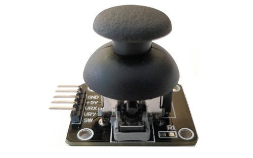
KY-023 Joystick Module
The KY-023 Joystick module is a compact, self-centering spring-loaded module similar to the analog thumbstick found on PlayStation 2 (PS2) controllers. It contains two variable resistors (potentiometers) and a momentary push button. The two potentiometers produce analog voltage outputs that represent the physical position of the joystick on the x-axis and y-axis. The push button produces a digital output that indicates whether the joystick cap has been pressed straight down.
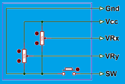
Each potentiometer on the KY-023 has a resistance of 10kΩ and is mechanically linked to one axis of the joystick shaft. As you tilt the joystick left or right, the resistance of the X-axis potentiometer changes, causing the output voltage on the VRx pin to vary between 0V and the supply voltage. Similarly, tilting the joystick up or down changes the Y-axis potentiometer resistance and the VRy pin voltage. When the joystick is centered, both outputs rest at approximately half the supply voltage.
The module operates with a supply voltage of 3.3V to 5V, making it directly compatible with the 3.3V logic of Raspberry Pi Pico without any level-shifting required when powered from the 3.3V rail.
Pinout
The KY-023 joystick module has 5 pins. Here is a description of each:
| Pin Number | Pin Name | Description |
|---|---|---|
| 1 | GND | Connect to the ground terminal of Raspberry Pi Pico |
| 2 | +5V | Connect to the 3.3V or 5V pin of Raspberry Pi Pico |
| 3 | VRx | Analog output voltage proportional to x-axis position (left/right) |
| 4 | VRy | Analog output voltage proportional to y-axis position (up/down) |
| 5 | SW | Digital output from the push button. HIGH when not pressed, LOW when pressed. |
How the Joystick Module Works
The KY-023 joystick module operates using two potentiometers and a gimbal mechanism. The gimbal is a pivot system that allows the joystick shaft to tilt in any direction along two independent axes. Each axis of the gimbal is mechanically connected to one potentiometer, so tilting the stick physically rotates the wiper of the potentiometer.
When the potentiometer wiper moves, the resistance between the wiper and one end of the resistive track changes. Since the potentiometer is connected as a voltage divider between the supply voltage and ground, the output voltage at the wiper pin changes proportionally to the wiper position. The Raspberry Pi Pico ADC reads this voltage and converts it to a digital value that your code can use to determine joystick position.
Moving the joystick left or right changes the VRx output voltage. Moving it up or down changes the VRy output voltage. Diagonal movement changes both simultaneously. When the joystick is released, the spring mechanism returns it to the center position, and both outputs return to their midpoint voltages (approximately half the supply voltage).
The push button is activated by pressing the joystick cap straight down. It is internally connected with a pull-up resistor on the SW pin, so the output is normally HIGH and goes LOW when pressed.
Raspberry Pi Pico ADC Channels
The Raspberry Pi Pico’s RP2040 chip includes a 12-bit SAR (Successive Approximation Register) ADC with four channels. Three of these channels are available on the physical GPIO pins, and the fourth is internally connected to the built-in temperature sensor. The available ADC pins are as follows:
| ADC Channel | GPIO Pin |
|---|---|
| ADC0 | GP26 |
| ADC1 | GP27 |
| ADC2 | GP28 |

The ADC supports polling, interrupt-driven, and FIFO/DMA transfer modes. The conversion speed is 2 µs per sample (500kS/s), since the RP2040 ADC clock runs at 48 MHz and takes 96 clock cycles per conversion:
96 x (1 / 48MHz) = 2 µs per sample (500kS/s)Although the ADC is 12-bit (0–4095), MicroPython’s read_u16() method scales the result to a 16-bit value (0–65535) for consistency across different microcontroller platforms.
Wiring: Joystick Module with Raspberry Pi Pico
You will need the following components:
- Raspberry Pi Pico
- KY-023 Joystick Module
- Connecting Wires
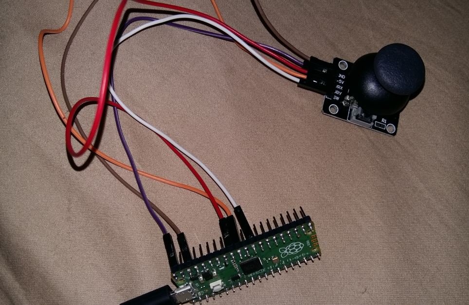
Connect the components as shown in the schematic diagram below:
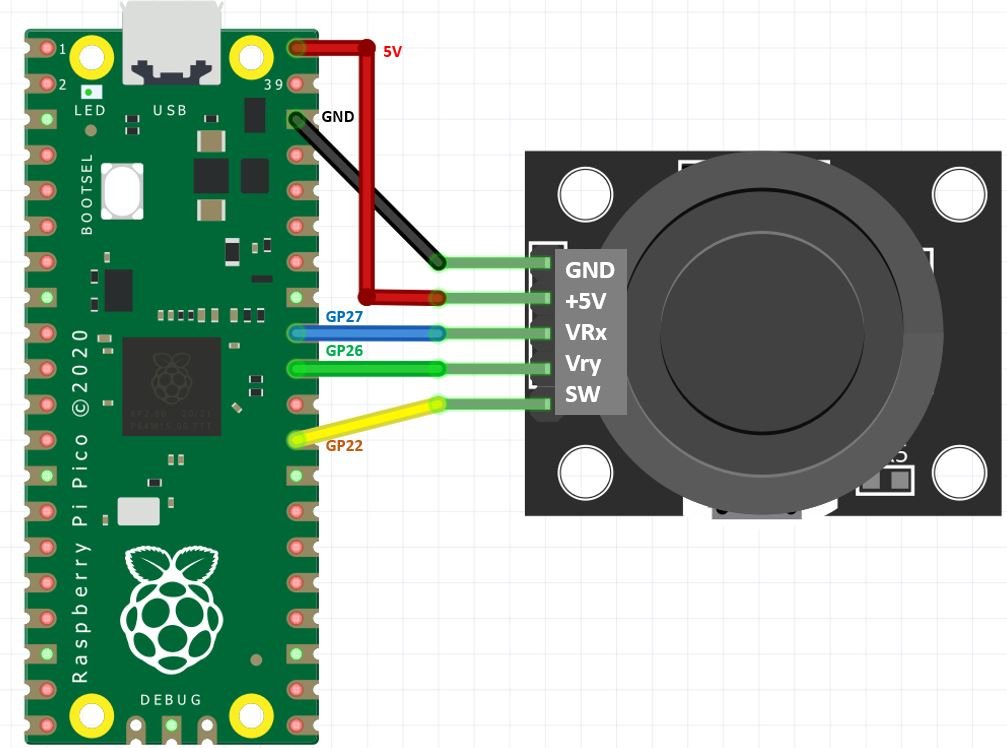
Connect the +5V pin of the joystick module to the VBUS (5V) or 3V3 pin of Raspberry Pi Pico depending on your module’s requirements. Connect GND to GND. Connect the VRx pin to GP27 (ADC1) and the VRy pin to GP26 (ADC0). Connect the SW pin to GP22, which we will configure as a digital input with a pull-up resistor in the code.
MicroPython Code: Reading Joystick Input
Open Thonny IDE and go to File > New to create a new file. Copy the following code and paste it into the editor. This sketch reads the x-axis, y-axis, and switch values from the joystick and prints them to the shell terminal every second.
from machine import Pin, ADC
from time import sleep

VRX = ADC(Pin(27))
VRY = ADC(Pin(26))
SW = Pin(22, Pin.IN, Pin.PULL_UP)

while True:
    xAxis = VRX.read_u16()
    yAxis = VRY.read_u16()
    switch = SW.value()

    print("X-axis: " + str(xAxis) + ", Y-axis: " + str(yAxis) + ", Switch: " + str(switch))
    if switch == 0:
        print("Push button pressed!")
    print(" ")
    sleep(1)
How the Code Works
At the top of the script, we import the ADC and Pin classes from the machine module. These allow us to interact with the analog and digital GPIO pins of the Raspberry Pi Pico. We also import sleep from the time module to add a delay between readings.
from machine import Pin, ADC
from time import sleep
We then create ADC objects for GP27 and GP26 to read the VRx and VRy analog outputs. GP22 is configured as a digital input with an internal pull-up resistor enabled using Pin.PULL_UP. This ensures the SW pin reads HIGH when the button is not pressed.
VRX = ADC(Pin(27))
VRY = ADC(Pin(26))
SW = Pin(22, Pin.IN, Pin.PULL_UP)
Inside the main loop, we read the joystick positions using read_u16(). This method returns a value between 0 and 65535, where the 12-bit hardware ADC result has been scaled up to 16 bits by MicroPython. When the joystick is centered, both values should be close to 32767 (the midpoint). Moving the joystick fully in one direction will push the reading toward 0 or 65535.
xAxis = VRX.read_u16()
yAxis = VRY.read_u16()
We read the switch state using SW.value(), which returns 1 when the button is not pressed (HIGH due to pull-up) and 0 when the button is pressed (LOW when the circuit is completed to ground).
switch = SW.value()All three values are then printed to the Thonny shell terminal, followed by an additional message if the button has been pressed.
print("X-axis: " + str(xAxis) + ", Y-axis: " + str(yAxis) + ", Switch: " + str(switch))
if switch == 0:
    print("Push button pressed!")
Demonstration
Save the file with a .py extension (for example, joystick.py or main.py) and click the Run button in Thonny to upload and execute the code on your Raspberry Pi Pico. Make sure the correct board is selected under the interpreter settings.
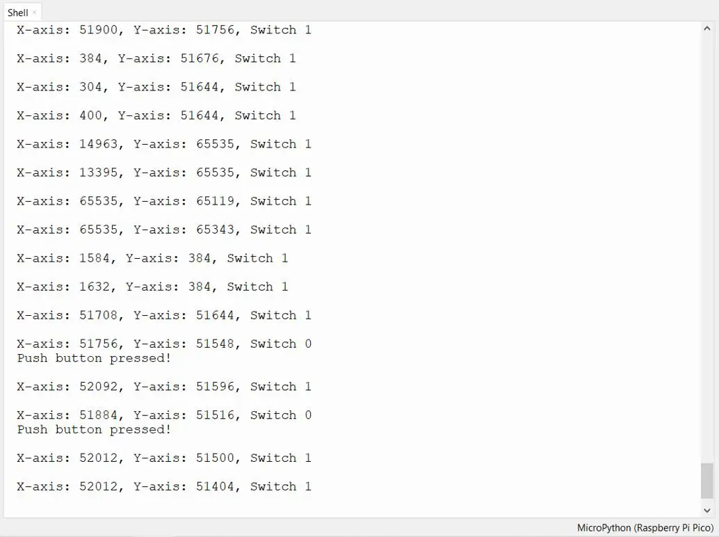
Move the joystick left, right, up, and down. You will see the X-axis and Y-axis values change in the Thonny shell terminal. When you push the joystick cap straight down, the switch value changes from 1 to 0 and the message “Push button pressed!” appears.
Calibration and ADC Precision
One limitation to be aware of when using the KY-023 joystick with Raspberry Pi Pico is ADC precision. The RP2040’s ADC has a few known issues: it can exhibit noise, non-linearity, and a slight offset from the ideal center point. Because of this, the resting center position of the joystick may not read exactly 32767 — you might see values like 31500 or 33200 instead.
To handle this in your code, you can implement a dead zone — a range of values around the center that your program treats as “no movement.” For example:
CENTER = 32767
DEAD_ZONE = 3000

xAxis = VRX.read_u16()
if abs(xAxis - CENTER) < DEAD_ZONE:
    print("X-axis: Center")
elif xAxis < CENTER:
    print("X-axis: Left")
else:
    print("X-axis: Right")
This approach prevents false movement detection caused by ADC noise or slight mechanical drift in the joystick's resting position. You can also calibrate the actual center value at startup by reading the joystick before the user touches it and storing that value as your reference center.
Practical Applications
The KY-023 joystick module is a versatile input device that can be used in a wide range of Raspberry Pi Pico projects:
- Robot control: Use the x-axis and y-axis values to control the speed and direction of a two-wheeled or four-wheeled robot. Map the joystick position to PWM duty cycles for motor drivers like the L298N.
- Servo motor control: Map the joystick position to servo angle values to build a pan-tilt camera mount or a robotic arm joint.
- Menu navigation: Use the joystick to navigate menus on an OLED or LCD display, scrolling through options by detecting up/down/left/right movements.
- Game controller: Build a simple game controller for a Pico-powered game displayed on an OLED or sent over USB HID.
- Drone or gimbal control: Map axis values to pitch and roll adjustments in a flight controller or camera stabilization system.
Troubleshooting
Here are some common issues you may encounter when using the joystick module with Raspberry Pi Pico and how to fix them:
Problem: X-axis or Y-axis always reads 0 or 65535
This usually means the VRx or VRy wire is not connected correctly. Check that GP27 is connected to VRx and GP26 is connected to VRy. Also confirm that the GND and power connections are secure.
Problem: Switch never changes state
Make sure the SW pin is connected to GP22 and that you have enabled the internal pull-up resistor in the code using Pin.PULL_UP. Without the pull-up, the pin may float and give unreliable readings.
Problem: Values are very noisy or jittery
ADC noise is normal with the RP2040. To reduce noise, connect a 100nF decoupling capacitor between the AGND and ADC reference pins. You can also average multiple readings in software to smooth out the values:
samples = [VRX.read_u16() for _ in range(10)]
xAxis = sum(samples) // len(samples)
Problem: Center position does not read ~32767
This is expected due to manufacturing tolerances in the potentiometers and ADC non-linearity. Implement a dead zone as shown in the calibration section above, or read the resting value at startup to establish your own center reference.
Problem: Code throws an error about ADC pin
Make sure you are using GP26, GP27, or GP28 for ADC input. Only these three GPIO pins are connected to ADC channels on the Raspberry Pi Pico. Using any other GPIO pin as an ADC input will raise an error.
The KY-023 joystick module is a great analog input device for Raspberry Pi Pico projects. While the RP2040 ADC has some limitations compared to dedicated ADC chips, it is more than adequate for most joystick-based control applications when combined with proper dead zone handling and optional software averaging.
You may also like to read:
- Joystick Module Interfacing with PIC Microcontroller
- Interface MG995 Servo Motor with Arduino
- Joystick-Based Servo Motor Control using Arduino
- KY-038 Microphone Sound Sensor Module with Arduino
- MAX6675 K-Type Thermocouple with Arduino
Other Raspberry Pi Pico tutorials:
- TM1637 4-Digit 7-Segment Display with Raspberry Pi Pico
- Data Logger with Raspberry Pi Pico and Micro SD Card
- Interface Micro SD Card Module with Raspberry Pi Pico
- RC522 RFID Reader Module with Raspberry Pi Pico
- NEO-6M GPS Module with Raspberry Pi Pico using MicroPython
- 28BYJ-48 Stepper Motor with Raspberry Pi Pico using MicroPython