In this joystick based servo motor control tutorial, we will control two servo motors using a joystick module and Arduino. Firstly, we will first learn how to use joystick module and interface it with Arduino and then we will see an example of joystick based servo motor control by using two servo motors.
The joystick we are using is analog and it provides more accurate readings than the simple directional joysticks. To design a joystick based servo motor control project, you should know how to use the joystick module and how to interface the servo motor with Arduino. you may also like to check:
The KY-023 Joystick module is the simplest to use module and it adds greater flexibility to your projects. It can be used with many microcontrollers but we are using Arduino.
Recommended Components
The following components are used in this project or are helpful for building it with the Arduino.
| Component | How it’s used in this project | Buy on Amazon |
|---|---|---|
| Arduino Uno R3 | The main microcontroller board that runs the project code and controls all connected components. | Check Price |
| Joystick Module | Provides the X/Y analog input used to set the servo position. | Check Price |
| Servo Motor (SG90) | Rotates to the angle commanded by the joystick reading. | Check Price |
| Breadboard | Lets you build and prototype the circuit without soldering. | Check Price |
| Jumper Wires | Used to make the connections between the Arduino, breadboard and the modules. | Check Price |
As an Amazon Associate we earn from qualifying purchases. Prices and availability are accurate as of the date/time indicated and are subject to change.
KY-023 Joystick module
The Joystick module is a very simple self-centered spring-loaded module similar to S2 (PlayStation 2). It consists of two variable resistors and a push button. Variable resistors provide output in the form of analog voltage and push-button provides output in digital form either low state or high state. One Potentiometer is for x-axis control and another Potentiometer is for Y-axis control.
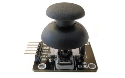
An important thing to note here is that the Joystick features two 10k potentiometers one for each axis that provides variable voltage. The KY-023 joystick module aims to provide two-dimensional (x-axis and y-axis) motion to a microcontroller.
There is a push-button at the center which is used to control the z-axis dimension. It is turned on when you press the black cap down.
PinOut
The joystick module consists of 5 pins. The description of each pin is given below:
| Pin Number | Pin Name | Description |
|---|---|---|
| 1 | GND | Connect to ground terminal of Arduino |
| 2 | +5v | Connect 5-volt pin of Arduino |
| 3 | VRx | It provides voltage w.r.t x-axis position of the joystick. (left/right) |
| 4 | VRy | It provides voltage w.r.t Y-axis position of the joystick. (up/down) |
| 5 | SW | Switch at the center. This pin gives the output obtained from the push button. When the push button is released the output will be HIGH and when it will be pressed the output will be LOW. |
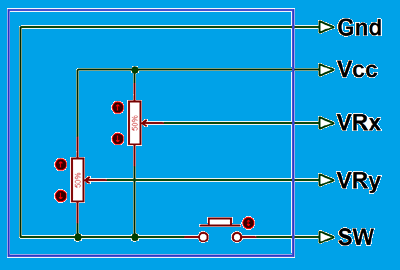
The internal circuit diagram of the joystick module is shown below:
Joystick Module Working
The Joystick Module works on the basic principle of two potentiometers and a Gimbal Mechanism. These two mechanisms make it easier to determine the position of the Joystick (right, left, up, and down) using the Arduino board.
Each potentiometer is connected to each of the Joystick’s shafts. They are used to determine the position of the rod. The position is interpreted as analog values from the Arduino board.
The resistance of the potentiometer changes as the joystick’s physical position is varied. This change is measured through the ADC pins of the Arduino board. Analog pins in the Arduino board are marked with the letter ‘A’ e.g. A0, A1, A2, A3, A4. They have 5 built-in analogs to digital converter channels. Only these analog pins of Arduino can be used to measure analog signals.
When we move joystick module on the left or the right side value of VRX varies. When we move this module up or down, the value of VRY varies. When we move it in diagonal direction values of both VRX and VRY vary. When we press it in the middle position, the SW pin becomes high. The values of VRX, VRY, and SW changes according to the picture shown below.
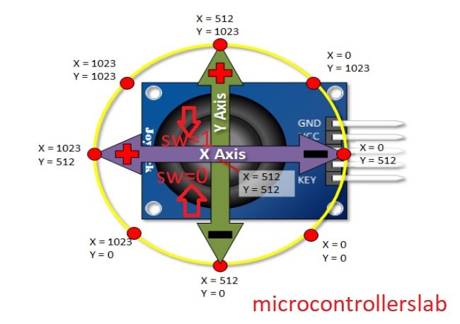
You may notice in the diagram above that the value varies between 0-1023. This is because in Arduino UNO each analog channel is a 10-bit ADC. Therefore the values are between 0-1023.
Interfacing Joystick Module with Arduino
Following components are required:
- Arduino
- Joystick Module
- Connecting Wires
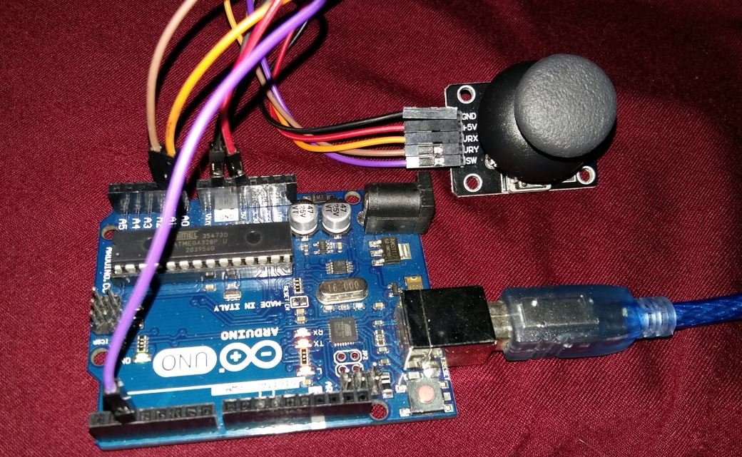
Follow the schematic diagram below:
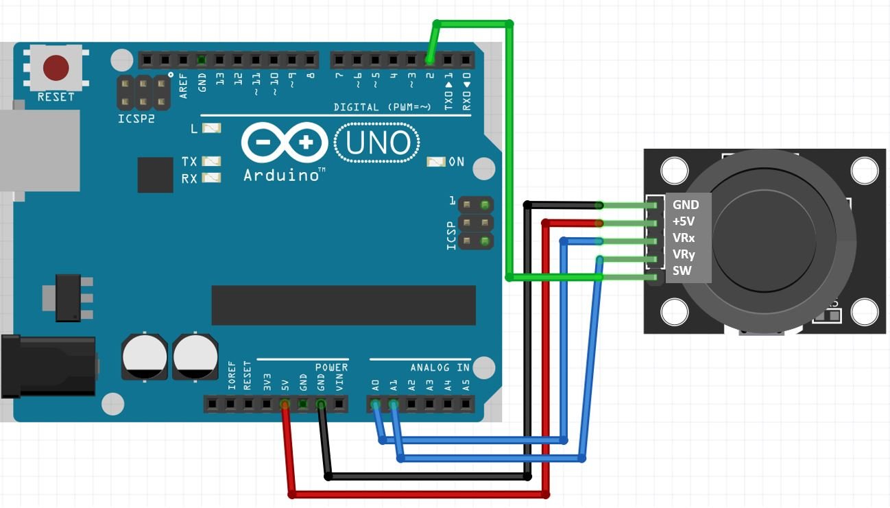
As you may see, the Joystick module has 5 pins which we will connect with the Arduino board. Connect +5V pin of joystick module with 5V Arduino pin. Then connect both the GND pins together. We have used analog pins A0 and A1 of the Arduino board to connect with VRx and VRy pins of the joystick module respectively. Additionally, we have connected digital pin 2 of Arduino with the SW pin of the module. You can use any appropriate analog pin of Arduino to connect with VRx and VRy pins and any appropriate digital pin of Arduino to connect with SW.
Arduino Sketch: Reading analog/digital input from Joystick Module
Open your Arduino IDE and go to File > New to open a new file. Copy the code given below in that file.
This sketch will display on the serial monitor, the Joystick physical positions in terms of x and y coordinates. Moreover, the switch output will be shown as well.
int x_key = A0;                       // initializing A0 for storing the joystick’s x key value
int y_key = A1;                      // initializing A1 for storing the joystick’s y key value
int Push_Button = 2;                // initializing digital pin 2 for joystick’s press to select button
int Horizontal_Position = 0;       // Declaring a variable for storing the value
int y_Position = 0;               // Declaring a variable for storing the value
int button_State = 0;            // Declaring a variable for storing the value

void setup ( ) {
  Serial.begin (9600) ;         // initializing serial communications at 9600 bps:
  pinMode ( x_key, INPUT ) ;   // Selecting Arduino analog A0 pin as input
  pinMode ( y_key, INPUT ) ;  // Selecting Arduino analog A1 pin as input
  pinMode (Push_Button, INPUT_PULLUP ) ;     // This will activate pull-up resistor on the push-button pin

  // If you have Arduino version previous to Arduino 1.0.1, then use these commands for activating pull-up resistor.
  // pinMode ( button_Pin , INPUT ) ;
  // digitalWrite ( button_Pin , HIGH ) ;
}

void loop ( ) {

  Horizontal_Position = analogRead (x_key) ;  // Reading the value from A0 and storing in Horizontal_Position
  y_Position = analogRead (y_key) ;           // Reading the value from A1 and storing in y_Position
  button_State = digitalRead (Push_Button) ;     // Reading the digital pin 2 is high or low
  Serial.print (" Value of X key is ") ;       // Printing “ Value of X key is ” on the display
  Serial.print (Horizontal_Position) ;        // Printing value of x key on the display
  Serial.print (" | Value of Y key is ") ;   // Printing “ Value of Y key is ” on the screen
  Serial.print (y_Position) ;                // Printing value of y key on the display
  Serial.print (" | Button State is ") ;     // Printing “ Button state ” on the display
  Serial.println (button_State) ;           // Printing the button is high or low on the display
  delay (1000) ;                           // This will add delay between readings

}
How the Code Works?
We will first define the analog and digital pins that we have connected with the VRx, VRy, and SW pins of the Joystick module.
int x_key = A0;
int y_key = A1;
int Push_Button = 2;
Next we will declare three int varaibles to hold the x value, y value and the push button state. Initially, they are set to 0.
int Horizontal_Position = 0;
int y_Position = 0;
int button_State = 0;
Inside the setup() function we will first open the serial communication at a baud rate of 9600. Next, we will configure the VRx and VRy pins as input using the pinMode() function. Also, we will configure the push button pin as an input and activate pull-up resistor on the push-button pin as well. Then we will set this pin to HIGH initially. The SW pin is HIGH when the push button is not pressed.
void setup ( ) {
  Serial.begin (9600);
  pinMode (x_key, INPUT);
  pinMode (y_key, INPUT);
  pinMode (Push_Button, INPUT_PULLUP);

  // If you have Arduino version previous to Arduino 1.0.1, then use these commands for activating pull-up resistor.
  // pinMode (button_Pin , INPUT);
  // digitalWrite (button_Pin , HIGH);
}
Inside the loop() function, we will first read the value from the A0 pin to get the x position values and then read the A1 pin to get the y position values. This is done by using analogRead() and first passing x_key pin and then y_key pin we will acquire the x and y-axis positions of the joystick.
  Horizontal_Position = analogRead (x_key);
  y_Position = analogRead (y_key);
Next we will read the switch output. This will be achieved using the digitalRead() function and passing the pin as a parameter inside it. This function will return ‘1’ if the SW output is HIGH and ‘0’ if the SW output is LOW. Note that a HIGH output means push button is not pressed and a LOW output means the push button is pressed.
button_State = digitalRead (Push_Button) ; All these three readings SW, VRx and VRy will be displayed in the serial monitor after every second.
  Serial.print (" Value of X key is ") ;
  Serial.print (Horizontal_Position) ;
  Serial.print (" | Value of Y key is ") ;
  Serial.print (y_Position) ;
  Serial.print (" | Button State is ") ;
  Serial.println (button_State) ;
  delay (1000) ;
Demonstration
Choose the correct board and COM port before uploading your code to the board.
Go to Tools > Board and select Arduino.

Next, go to Tools > Port and select the appropriate port through which your board is connected. Click on the upload button to upload the code into the Arduino development board. After you have uploaded your code to the Arduino press its RST button.
Now open the serial monitor and set the baud rate to 9600. Move the joystick in different directions and you will be able to view the corresponding x-axis and y-axis positions along with the switch output. Now press the push button. The switch output will now be ‘0’.
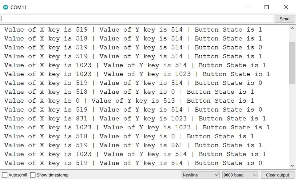
Notice how the x-axis and y-axis values vary as you move the joystick. This will be helpful to understand the different physical positions of the joystick.
Joystick based servo motor control using Arduino with two servo motors
Now after learning how to use the joystick module let us control two servo motors with the help of the joystick. We will be using SG-90 servo motors for this guide. Let us first learn about them.
SG-90 Servo Motor
SG90 is a low-cost and high-output power servo motor. It can rotate up to 180 degrees and each step can be of maximum of 90 degrees. Moreover, it is small enough that it can easily fit into your robotics ARM or obstacle avoidance robotics projects. On top of that, it requires only one output pulse signal to control its movement.
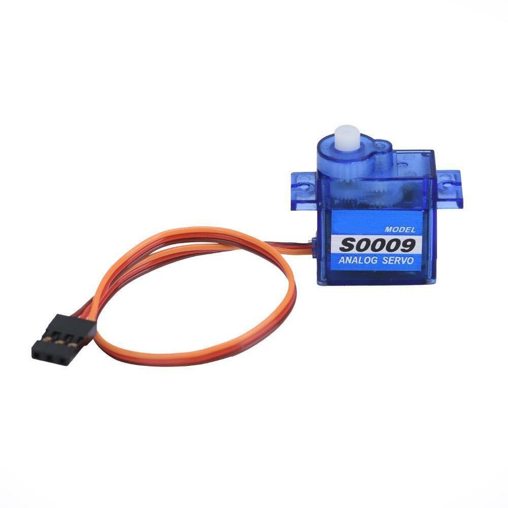
The following figure shows the pinout diagram of SG90 servo motor. It consists of three pins only such as PWM, ground and Vcc pin. Brown, orange and red wires are GND, Vcc and PWM pins respectively. Details and functionality of each pin is listed in the next section.
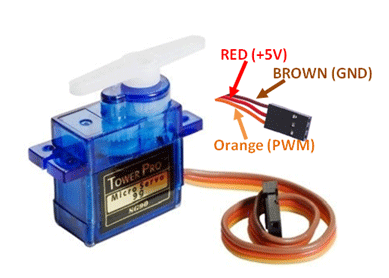
Pin Configuration Details
Vcc and ground, as their name suggests, are the power supply pins which are used to power servo motor. Only 5 volts of power signal is required to power this motor. Mostly microcontrollers or development boards have onboard 5 volts supply which we can use to power SG90 servos.
This table briefly describes all three pins:
| Wire of motor | Possible colors of each wire |
|---|---|
| Vcc pin | Red |
| GND pin | Black, or brown |
| Control Signal / PWM pin | Yellow, orange, or white |
Interface Joystick and Servo Motors with Arduino
Components Required
So now we will see how we can control two servo motors with the help of joystick module. We are using two servo motors. One servo motor can be controlled with x-axis of joystick module and other servo motor is being controlled with y-axis of joystick module. In this example, we will control 2 servo motors using a joystick. This example is used in many projects like game controllers and electronics toy cars.
Required Components
- 2 SG-90 servo motors
- KY-023 Joystick module
- Arduino UNO (you can use any)
- Breadboard
- Connecting Wires
The servo motor has three connections which are
- Positive
- Negative
- Signal
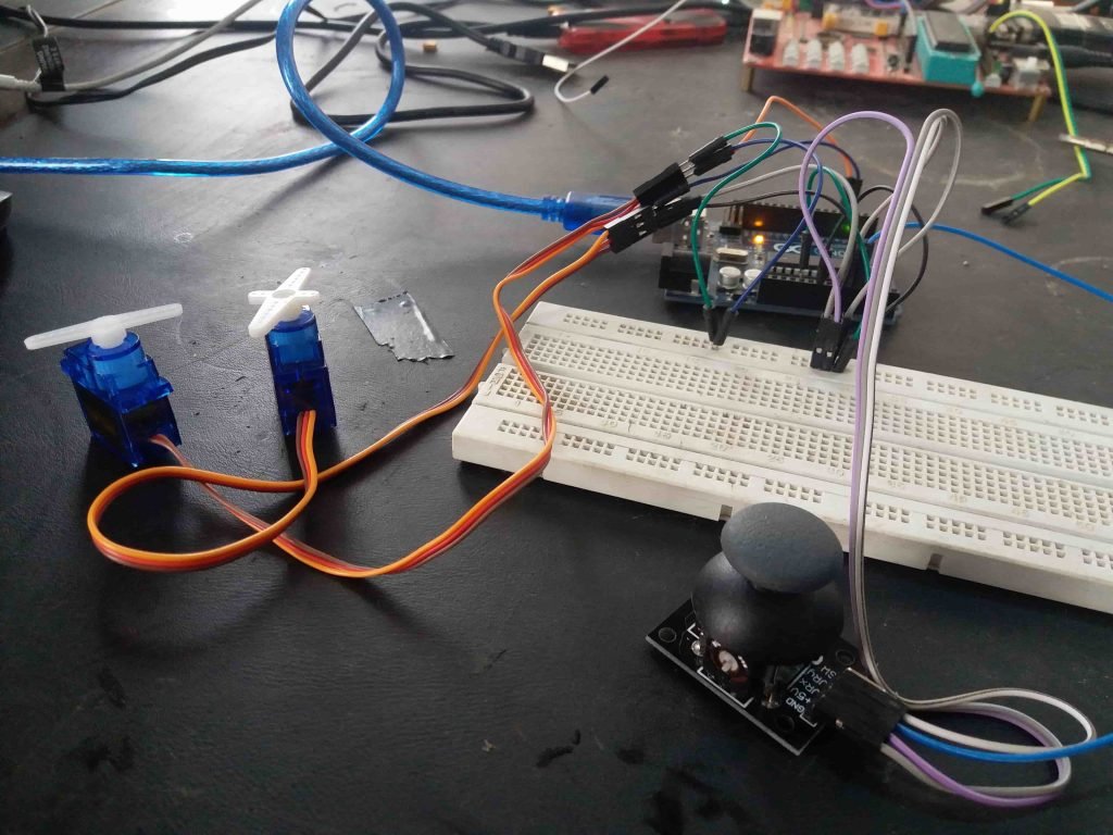
The connections are very easier. Connect the servos and joystick as shown in the figure.
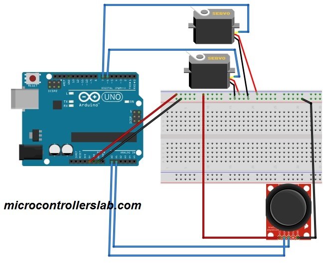
Follow the connections as shown in the tables below:
| Servo Motor 1 | Arduino UNO | Joystick Module |
| VCC | 5V | VCC |
| GND | GND | GND |
| Signal | Pin 6 | – |
| Servo Motor 2 | Arduino UNO | Joystick Module |
| VCC | 5V | VCC |
| GND | GND | GND |
| Signal | Pin 7 | – |
Moreover, connect VRX pin of Joystick module with A0 pin of Arduino and VRY pin of Joystick module with A1 pin of Arduino.
Arduino Sketch Controlling Servo Motor with Joystick
Open your Arduino IDE and go to File > New. A new file will open. Copy the code given below in that file and save it.
// Controlling 2 Servos Using a Joystick.
#include < Servo.h >                       // including the library of servo motor

int First_Signal_Pin = 6 ;                // initializing pin 6 for first servo
int Second_Signal_Pin =  7 ;         // initializing pin 7 for second servo
int Horizontal_Joystick_Pin = A0 ;  // initializing A0 for horizontal movement
int Vertical_Joystick_Pin = A1 ;  // initializing A1 for vertical movement

// initializing the min and max values for horizontal and vertical movement
int Horizontal_Min = 0 ;
int Horizontal_Max = 180 ;
int Vertical_Min = 0 ;
int Vertical_Max = 180 ;

Servo First_Servo ;
Servo Second_Servo ;

// Declaring variables for storing values
int Horizontal_Value ;
int Horizontal_Servo_Value ;
int Vertical_Value ;
int Vertical_Servo_Value ;

void setup ( )
{
  First_Servo.attach ( First_Signal_Pin ) ;                       // Enabling pin 6 for first servo
  Second_Servo.attach ( Second_Signal_Pin ) ;                    // Enabling pin 7 for first servo
}

void loop ( )
{
  Horizontal_Value  = analogRead ( Horizontal_Joystick_Pin ) ;  // Reading the value from A0
  Vertical_Value  = analogRead ( Vertical_Joystick_Pin ) ;    // Reading the value from A1

  // Mapping the values for horizontal and vertical movement of joystick.
  Horizontal_Servo_Value  = map ( Horizontal_Value, 0 , 1023, ServoH_Min , ServoH_Max ) ;
  Vertical_Servo_Value  = map ( Vertical_Value, 0, 1023, ServoH_Min , ServoH_Max ) ;

  // Moving the servos
  First_Servo.write ( Horizontal_Servo_Value ) ;
  Second_Servo.write ( Vertical_Servo_Value ) ;
  delay ( 2000 ) ;    // Delay of 2 seconds
}
How the Code Works?
Firstly we will include the built-in Servo.h library.
#include <Servo.h> Next we will declare the Arduino pins connected with the servo motor’s signal pin. The first servo motor is connected with digital pin 6 and the second servo motor is connected with digital pin 7.
int First_Signal_Pin = 6 ;                // initializing pin 6 for first servo
int Second_Signal_Pin =  7 ;         // initializing pin 7 for second servo
Then we will declare additional two int varaibles to define the analog pins that we have connected with the VRx and VRy pins of the Joystick module.
int Horizontal_Joystick_Pin = A0 ;  // initializing A0 for horizontal movement
int Vertical_Joystick_Pin = A1 ;  // initializing A1 for vertical movement
We will set the maximum and minimum values for both the horizontal and vertical positions. This is because the servo arm’s position can vary from 0-180 degrees.
int Horizontal_Min = 0 ;
int Horizontal_Max = 180 ;
int Vertical_Min = 0 ;
int Vertical_Max = 180 ;
Then we will create objects of this library for each motor.
Servo First_Servo ;
Servo Second_Servo ;
The following int variables will store the Joystick’s horizontal value, vertical value and the servo motor’s horizontal, vertical values.
int Horizontal_Value ;
int Horizontal_Servo_Value ;
int Vertical_Value ;
int Vertical_Servo_Value ;
Inside the setup() function, we will attach the Arduino digital pins connected with the signal pin of the servo motors with both the servo objects.
void setup ( )
{
  First_Servo.attach (First_Signal_Pin) ;                       // Enabling pin 6 for first servo
  Second_Servo.attach (Second_Signal_Pin) ;                    // Enabling pin 7 for second servo
}
Inside the loop() function, we will first obtain the horizontal and vertical values from the Joystick module by using analogRead() and pass the analog pins connected with VRx and VRy as parameters inside it.
  Horizontal_Value  = analogRead ( Horizontal_Joystick_Pin ) ;  // Reading the value from A0
  Vertical_Value  = analogRead ( Vertical_Joystick_Pin ) ;    // Reading the value from A1
Next we will map these values to get values for the servo motor’s horizontal and vertical positions. Note that the Joystick module gives values between 0-1023 however the servo motor’s arm moves through 0-180 degrees.
  Horizontal_Servo_Value  = map ( Horizontal_Value, 0 , 1023, ServoH_Min , ServoH_Max ) ;
  Vertical_Servo_Value  = map ( Vertical_Value, 0, 1023, ServoH_Min , ServoH_Max ) ;
Finally, we will move both the servo motors by using the write() method on the servo objects. Here we are passing the ‘Horizontal_Servo_Value’ variable as a parameter inside this function for the first motor and ‘Vertcal_Servo_Value’ variable as a parameter for the second motor. This will position the servo arm according to the values held in the two variables that will vary from 0-180 degrees.
  First_Servo.write (Horizontal_Servo_Value) ;
  Second_Servo.write (Vertical_Servo_Value) ;
  delay (2000) ;    // Delay of 2 seconds
Demonstration
To see the demonstration of the above code, upload the code to Arduino. Before uploading the code, make sure to select Arduino UNO from Tools > Board.
Also, select the correct COM port to which the Arduino board is connected from Tools > Port.
Once the code is uploaded to your board, move the Joystick and the servo motors will start rotating. When you move the Joystick horizontally, the first servo motor will rotate. Similarly, when you move the Joystick vertically, the second servo motor will rotate.
Watch the video demonstration below:
You may also like to read:
- MAX30102 Pulse Oximeter and Heart Rate Sensor with Arduino
- MAX30100 Pulse Oximeter and Heart Rate Sensor with Arduino
- Control Stepper Motor with A4988 Driver Module and Arduino
- DRV8825 Driver Module for Stepper Motor with Arduino
- Control 28BYJ-48 Stepper Motor with ULN2003 Motor Driver and Arduino
- Stepper Motor Control with L298N Motor Driver and Arduino
- Arduino L293D Motor Driver Shield Control DC, Servo, and Stepper Motors
- Stepper Motor Control with L293D Motor Driver IC and Arduino
- DC Motor Speed and Direction Control with L293D Driver IC and Arduino
hi, if i would like to control 4 servomotors with 2 joysticks with one arduino board. how i can do it?
I think you can just double the code
P.S: don’t forget to change the Doubled Variables.
Umm… your don’t pay attention on code. For FIRST ,why the int Horizontal_Joystick_Pin is used once as “Horizonta_Joystick_Pin ” ?? And why the **** is NOT defined the int ServoH_Min and ServoH_Max? By the way, what need to do ServoH_Min and ServoH_Max? Can you do a tutorial with an digital joystick? Because I don’t really know what joystick is.