A servo motor is a revolving or linear motion actuator that allows precise control of its linear velocity, acceleration, or angular position. This motor is available on the market with a sensor that pairs for feedback control. This motor has a sophisticated controller or a special kind of module for controlling its motion. A servo motor is not a special class of motor; actually, the servo word is for the motors, which use a control loop system. A servo motor usually interfaces with a microcontroller for control applications. We can see a simple servo motor with a feedback sensor in Figure 1.

Servo Motor Mechanism
The servo motor basically has three basic parts, which are as follows:
- Controlling Device
- Output Sensor
- Feedback system
The servo motor works on the basis of an automatic closed-loop system. That means we require a controller for this system, which has a comparator and a feedback path. The controller has two inputs and one output. In the controller, the comparator compares the output signal with the desirable reference signal for producing the input for the servo motor. The sensor senses the output signal. The input signal for the motor is the feedback signal.
The motor works on the basis of this feedback signal. The comparator signal is basically a logic signal for the motor. If the logical difference is high, then the motor will remain on for a specific time. As soon as the logical difference is low, the motor will be off for the desired time. Actually, in the controller, the comparator would decide whether the motor would be on or off. A good controller is mandatory for the proper functionality of this motor.
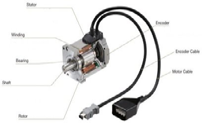
Construction of Servo Motor
A servo motor is a DC motor, which consist of following parts
- Stator winding
- Rotor winding
- Bearing
- Shaft
- Encoder
Stator Winding: The servo motor consists of two stator windings. The stator winding is wound on the stationary part of the motor, and we also refer to this winding as the field winding of the motor; this winding could be permanent magnets.
Rotor Winding: The servo motor also consists of two rotor windings. It is wound on the rotating part of the motor, and we refer to this winding as the armature winding of the motor.
Bearings: Bearings help in precise motion control. The servo motor consists of two bearings on the front and back sides for the free movement of the shaft.
Shaft: The shaft is basically the iron rod on which the armature winding is coupled.
Encoder: The encoder has an approximate sensor for telling the rotational speed and revolution per minute of the motor. For reference, we can see the construction of the servo motor in the figure below.
Working Principle of Servo Motor:
Servo motors are actually DC motors. Generally, all DC motors work on the principle of Fleming’s left-hand rule. This rule determines the direction of the force acting on the DC motor armature conductor. This rule tells us if we extend our left hand,index finger, middle finger, and thumb in such a way as we can see in the following figure:

Then the index finger shows the magnetic field, which is perpendicular to the direction of the current. For reference, see the middle finger in the figure. When we place the current-carrying conductor in a magnetic field, then the conductor experiences a force in that direction, which is perpendicular to both the direction of the magnetic field and the direction of the current. We can observe this by the thumb in Figure 3.
Servo Motor Control
From an experimental point of view, the controller or module controls the servo motor. Here, to understand the servo motor control, we will explain the control with an example. Consider a motor that rotates at a 45-degree angle with a given signal, then stops for some time and waits for further instructions. The shaft of this motor couples to another shaft with a gear assembly for decreasing the high rpm to the low rpm (revolution per minute) at the output side. We call this shaft the output shaft. We can see this in Figure 4.
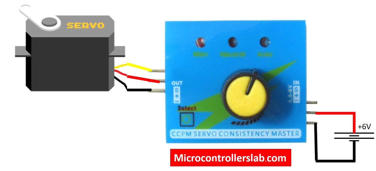
According to the figure, a potentiometer is present at the voltage-adjusting knob, and this knob couples with another gear assembly at the output shaft. During the rotation of the output shaft, the potentiometer knob also rotates, and the potentiometer creates the electrical potential according to the rotating output shaft. This electrical potential is basically the reference output signal.
Position Detection
When the shaft rotates from 0 to 45 degrees, the signal is produced according to this rotation. The reference output signal and reference input signal are given to the error detector amplifier. This error detector amplifier decides when the motor will be on and off. When the error detector amplifier shows a positive difference between the input reference signal and the output reference signal, then the motor moves in a forward direction to that angle according to the output shaft. When the error detector amplifier shows the negative difference, then the motor moves in the reverse direction for that angle. Similarly, when the error detector amplifier shows a zero difference, then the servo motor remains stationary for that time until the error of the error detector amplifier goes to positive or negative. These are the simple control logics of servo motor control.
Servo Motor Interfacing with Microcontroller:
A servo motor is one of the most special motors that we use for precise angular movement. The main advantage of this motor is that if we are controlling it with a microcontroller, then there is no need for a feedback controller or mechanism. This motor finds applications in industrial and commercial systems. Its working principle and operation are very simple. It consists of three wires: two wires are for the power of the motor, and the third is for the control signal. We can see servo motor control through ATMEL 8051 in Figure 5.
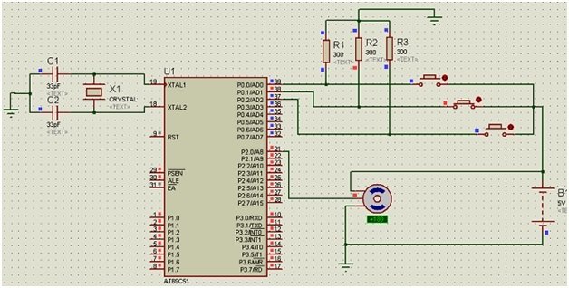
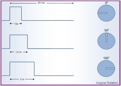
According to the figure, one wire connects to the VCC of the microcontroller, the second wire connects to the ground, and the third wire connects to any output port of the microcontroller. The output port connection of the microcontroller requires configuration through the code. The PWM (pulse width modulation) technique is useful for controlling the servo motor control signal and its angular position. 11.0592 MHz crystal oscillator is for clock pulse, and 22 Pf capacitor is for stable operation of crystal oscillator. Here the servo is used for changing the angular position from 0 to 180 degrees, and the duty cycle is controlled between 1 ms and 2 ms, as we can see in the figure below.
Applications of Servo Motors:
- It is used in robotic industry of position control.
- It is used in robotic arms.
- It is used in the press and cutting industry for cutting and pressing the piece precisely.
- It is used in the conveyer belt to start and stop the conveyer belt at every position.
- It is used in digital cameras for auto-focusing.
- It is used in solar tracking system for tracking the sun at every precise moment of time.
- It is used in the labeling and packing industry to label the monogram and pack the things.
Conclusion
In conclusion, this tutorial provide us with in-depth overview of servo motors. It also covers their working principle, construction, control, interfacing and applications. The interfacing with PIC microcontroller helps us better understand how the microcontroller can control a servo motor using control signal. You can utilize this concept to design and build more complex projects with a servo motor. Hopefully this was helpful in expanding your knowledge.
You may also like to read:
- Servo Motor with Raspberry Pi Pico using MicroPython
- Multilevel Inverters with Introduction, Types, Advantages and Applications
- types of oscillator used in microcontrollers
- Fuzzy Logic System: How fuzzy logic control system works?
- Introduction to Resistors and its Types
- Introduction to Capacitors – Types
This concludes today’s article. If you face any issues or difficulties, let us know in the comment section below.