The HUMANOID robotic ARM project aims to implement position control and vision control on the robotic arm. Industry recognizes the proficiency and precision of robots in various fields of work, such as VLSI chip design and fabrication, and handling high temperatures in modern steel industries. These robots constantly perform demanding tasks with accuracy and efficiency.
The webcam acts as an image capturing device for implementing the “Vision Control” system, and the software “Matlab” serves as the brain of the project to apply image processing algorithms for calculating the coordinates of the obstacle. The system captures the image, converts it to grayscale, and applies thresholding. Then, it applies an elliptical grid over the entire image. Among all the intersections in the grid, the algorithm selects the rectangular coordinates of one point that is most likely to be the center of the obstacle. The system assumes that the obstacle has sufficient contrast compared to the white background. Additionally, you may find the following articles about the humanoid robot relevant and interesting:
- Electrical projects ideas
- PIC BASED projects ideas
- solar sysem projects ideas
- Pure sine wave inverter A-Z
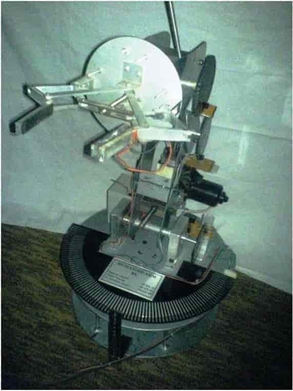
What is Humanoid Robotic Arm?
A humanoid robotic arm is a mechanical arm designed to resemble and function similarly to a human arm. It is a complex robotic system that consists of various parts, including a base, shoulder, arm, wrist, and gripper. These parts are connected through joints and can move in different directions, allowing the robotic arm to perform a wide range of tasks.
A humanoid robotic arm mimics the movements and capabilities of a human arm. Various industries and applications employ it, including industrial automation, manufacturing, healthcare, research, and even space exploration.
Humanoid Robotic Arm Using PIC Microcontroller
The slotted disk and sensor arrangement require the coordinates to be in the form of (θ), where θ represents the angular displacement of the base disk in the x-y plane. We need to develop a calibration equation that calculates the number of slots by mapping against the coordinates so that each motor can receive the coordinates in the number of integral slots between the extreme values (such as the minimum and maximum for the base disk). For all motors, except the gripper, we apply the above-stated methodology to offer variation in both θ and R.
The feedback control or the “Position Control” is implemented using a microcontroller called “PIC16F877A,” which acts as the heart of the project. The microcontroller receives the number of slots for each motor from the PC (Matlab 7) via a serial cable and is responsible for precisely taking the robotic arm (gripper) to the obstacle.
The PIC microcontroller ensures that it energizes each motor in the structure (and keeps the associated component of the arm moving) until the gripper reaches the exact location where the obstacle is placed. Sensors provide feedback to the PIC, reporting the arm’s position at each moment. Then, the PIC energizes the gripper motor to enable the picking of the obstacle.

Part of a HUMANOID Robotic Arm
MOTORS:
The motors use a pic microcontroller as the main muscles of our humanoid arm. We use these motors at locations in the structure where motion is required, whether it is rotational or angular. Depending on the locations, the motors of various torques, speeds, power, and sizes have been chosen for the appropriate function, considering the load attached to the motors at these locations and the height from the ground level.
Although these motors have different properties according to their usage but all are basically Direct Current Motors usually called DC Motors. The basic parts included in the construction of any DC Motor which are the same for all DC motors are:
- The stator is the stationary part of the dc machine.
- Field magnets are used to produce the main magnetic flux in which the current carrying conductor is placed. These can be either permanent type or produced electrically.
- The yoke is the outer shell of the motor which is used for protection and it holds the magnets.
- The rotor is the rotating part of the motor. It contains the following parts:
- The armature coil is the coil in which current flows and upon the action of the magnetic field, a force acts on this coil resulting in the rotations of the rotor.
- The shaft is the part of the motor on which the armature coil is placed.
- The commutator consists of commutator segments. It is the part of a dc machine which cannot be ignored. It keeps the current flow in only a single direction, hence causing a constant rotation of the rotor in a single direction. The commutator is also located on the shaft near the top. It is mostly the split ring type.
- Brushes are the part which slides over the commutator segments as the rotor rotates. These brushes connect the power supply terminals with the armature coil through the commutator. These brushes are usually made of carbon and are commonly known as carbon brushes.
- Power terminals are connected with the carbon brushes. These terminals come out of the stator where we connect the DC supply. The structure of a DC motor is shown in the following figure.
The DC motor works on the principal of Faraday’s Law of Electromagnetic Induction , which states as:“Whenever a current carrying conductor is placed in the magnetic field, it experiences a force whose magnitude and direction depends upon the cross product of magnetic field flux vector B and current I in the armature winding.”
DC MOTORS USED:Depending upon these requirements following are the types of motors which are being used in our project the humanoid arm using microcontroller:
- Wiper Motor ( quantity=2)
- Johnson Motor ( quantity=3)
WIPER MOTOR:This type of motor is called a “gear head” or “gear motor” and has the advantage of having lots of torque.The standard voltage requirement for the wiper motor is 12 volts DC. The electrical system in our robot usually puts out voltage between 13 and 13.5 volts, so it’s safe to say the motor can handle up to 13.5 volts with no problem.
The minimum required current for the motor is 1.6 amps at 70 rpm, 0.9 amps at 41 rpm (and 4 amps if you elect to run it at 106 rpm. These current ratings are for the motor spinning with no load. As we add mechanical load, these numbers can increase dramatically, doubling or even tripling under a heavy load. (When testing for torque, I found the motor to draw close to 14 amps in a stalled condition.) This factor must be taken into account when selecting a power supply. Since the motor will only use what it needs when it comes to current, it’s best to provide a source with a higher current rating than you think you might need. I would recommend a 5 amp or greater supply to handle most circumstances.Most power sources are labeled as to their output current. Be aware that the milliamp (or ma) is 1/1000 of an amp, so something labeled 500 ma is only 1/2 amp, and probably will not drive the motor.
JOHNSON MOTOR:
It is a very power DC motor. Johnson is the name of the company which is manufacturing DC motors. We have chosen this type of motor because of its cheap price. This is a gear reduced dc motor. We did not put load directly on the shaft of the motor but converted its rotary motion into linear motion by using mechanical assembly.
The specifications of the Johnson motor being used in our project is
- 16,000 RPM
- 12 VDC
- Draw 1.8 Amp
- Shaft Size 1/8″ (D) X 3/8″ (L)
- Diameter 1.5″ X 3″ long 2.5mm
- Mounting Holes in front
- Fully Reversible Great for RC Boats and other Application
BEARINGS:A bearing is a device to allow constrained relative motion between two or more parts, typically rotation or linear movement. Bearings may be classified broadly according to the motions they allow and according to their principle of operation as well as by the directions of applied loads they can handle. For individual balls that are sometimes called “ball bearings”. In HUMANOID robotic ARM we are using bearings at two locations. These are named as:
- Shoulder Bearing
- Base Disc Bearing Design
The type of bearing used for the both is ball bearing. The size of the ball bearing used with shoulder is kept a little higher than the base disk bearing, because of the difference in their width
SHOULDER BEARING:This is just a ball bearing of dia. 1 inch. It is placed in to a rectangular support made of aluminum.
BASE DISC BEARING DESIGN:It is a combination of six ball bearings attached to six L-shaped structures. On one side of these L-shaped structures lies a ball bearing and the other side is connected under the circular rotating disc. These six similar structures arranged symmetrically, make up the Base Disc Bearing Structure.
Materials in HUMANOID Robotic Arm
Material usage in HUMANOID robotic ARM has been divided into following two major types depending upon its usage and properties:
- Material for Sensor Disc for robotic arm
- Material for robotic arm’s main body
MATERIAL FOR SENSOR DISCS:The material being used for the sensor discs is black opaque synthetic plastic. Plastic is chosen because of its property that it is very softer than any metal. With this benefit it is possible to create slots for the sensor disc in it with high accuracies, short time creation and easy cutting. We used a laser cutter for making such slots.
The main body of the robotic arm uses stainless steel and aluminium as its materials. Stainless steel is used at locations where heavy load-bearing is required, such as the base, base disc, and shoulder. The base disc is made from a 3.5mm thick steel sheet, while the shoulder is made from a 2mm thick steel sheet. Aluminium is used in areas where lighter parts are needed, such as the arm, wrist, and gripper. The arm is made from a 2.5mm thick aluminium sheet, while the wrist is made from a 2.5mm thick aluminium sheet.
Hardware Designing: Humanoid Robotic Arm
Our structure consists of the following parts.Each part is described as follows:
BASE DISK
Base consists of an assembly of three circular disks: one moving and two stationary. All three disks are made of stainless steel. The first disk touches the ground, providing support for the entire structure. Above the first disk, six stainless steel rods are welded. On the other end of the rods, disk two is welded. The wiper motor is fixed with disk 2. Above disk two, the rotating disc structure, including the six ball bearings attached to the six L-shaped rods, rotates. This disk is referred to as the rotating base disk number 3.
SHOULDER
The shoulder consists of two parallel wide strips of stainless steel that are joined together from the center. The center also features a nut to which the shaft of the wiper motor is attached. The wiper motor is situated on the rotating base disc, and the entire shoulder structure rests on it. The shoulder structure can move smoothly in the vertical plane, ranging from approximately 0 degrees to about 120 degrees, with respect to the circular disc.
ARM
The arm also consists of two parallel strips of aluminum joined together at the center. The whole assembly of the arm is mounted on the shoulder of the humanoid. These two parts are connected using a freely movable shaft. On the shorter end side of the arm, a nut is connected through which the shaft of the Johnson motor passes. This motor is located on the shoulder strips of the structure. The motor remains stationary with respect to the shoulder and doesn’t move it, but when it rotates, with the help of the shaft and nut arrangement, the arm part of the structure moves upwards or downwards. It can move without any hindrance in the vertical plane from about 30 degrees to about 120 degrees with respect to the shoulder.
WRIST
The wrist also consists of two parallel strips of aluminum joined together from the gripper end side. The whole assembly of the wrist is mounted on the arm of the humanoid structure. These two parts are connected using a freely movable shaft. On the shorter end side of the arm, a nut is connected through which the shaft of the Johnson motor passes. This motor is located on the arm strips of the structure. This motor remains stationary with respect to the arm and doesn’t move it, but when it rotates, with the help of the shaft and nut arrangement, the wrist part of the structure moves upwards or downwards. It can move without any hindrance in the vertical plane from about 30 degrees to about 120 degrees with respect to the arm.
GRIPPER
This is the most technical aspect of the mechanical design of a humanoid robotic arm and requires a significant amount of time. It is the part of the robot where the objective is to securely hold onto an object until commanded to release it. Here, a sophisticated structure is used at the two limbs of the gripper, which sends a signal to the control system when an object is grasped, resulting in the cessation of the gripping action. The gripper is made of aluminum. Additionally, a motor, nut, and shaft assembly are located here, enabling the gripping process.
Robotic ARM Electrical hardware components
- PIC16F877A microcontroller: Robotic arm can not do anything without getting some of kind of instructions either from human or from a intelligent device like microcontroller or digital signal processor. In this project PIC16F877A microcontroller is used which basically a main heart of humanoid robotic arm. It controls the all functions of robotic arm. Sensors are interfaced with PIC16F877A microcontroller. Sensor data is read by microcontroller and after that microcontroller provides certain instructions to motors according to position of robotic arm and sensors which are mounted on robotic arm.
- Optical sensor: SLOTTED OPTICAL SWITCHE OPB870 is used to detect presence of anything. Optical sensor internal circuit have one infrared light emitting diode and a photo transistor.
- H Bridge: H Bridge is used to control direction of motors connected with humanoid robotic arm. For more information on robotic arm check how to design H bridge .
- OPTICAL DISK : The diagram shown below is made in AutoCAD with 90 slots. The width of these slots is kept a little more than the aperture of the photodiode in the infrared transmitter to ensure proper operation of conduction and obstruction of light .Three other optical disks with similar shape but differing in no: of slots are attached with each other motor except gripp
- OPERATION of optical disk:In the diagram above is shown a disk with slots. As the sensor moves over these slots,Subsequent conduction and obstruction of light takes place as it crosses any slot, and logic Vcc appears at the output of the sensor if light path is clear and when blocked logic 0 (low voltage) appears. In this way the interrupts in the form of 1 and 0 are generated to the pic microcontroller, which takes actions to stop and start the motors on the basis of algorithm
- TROUBLESHOOTING: The pitch of the slots must be greater than the aperture of the IR sensor for reliable operation.The slotted disk must be of such material that completely blocks the light when its non slotted portion faces the IR transmitter otherwise the differentiable interrupts cannot be generated.The sensor must be wider enough to incorporate the disk easily without offering any hindrance to its motion.
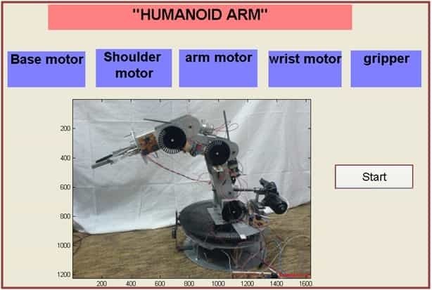
GUI of humanoid robotic arm using MATLAB
A graphical user interface (GUI) in matlab is shown below:
Conclusion
In conclusion, the Humanoid Robotic Arm project aims to implement position and vision control on a robotic arm, allowing it to perform demanding tasks with accuracy and efficiency. The project utilizes various components such as microcontrollers, sensors, motors, and optical disks to achieve precise movements and obstacle detection. The use of Matlab software as the brain of the project enables image processing algorithms to calculate the coordinates of obstacles. The combination of mechanical design and electrical hardware components creates a complex robotic system that mimics the movements and capabilities of a human arm. With its wide range of applications in industries such as automation, manufacturing, healthcare, and research, the Humanoid Robotic Arm project showcases the proficiency and precision of robots in various fields of work.
You may also like to read:
- WiFi Controlled Robot using Arduino and Blynk App
- Voice Controlled Robot using Arduino and Voice Recognition App
- accelerometer Based Hand Gesture Controlled Robot using Xbee
- Bluetooth Controlled Robot using pic microcontroller
- PICK AND PLACE MULTI-AXIS Robotic ARM
- Obstacle Avoidance Robot using Arduino
- Line follower robot using microcontroller