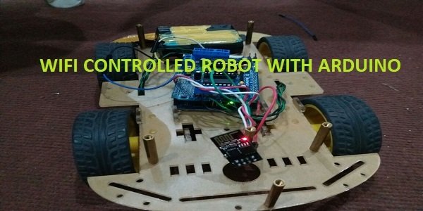
In this Arduino project, we will create a WiFi controlled robot using an ESP8266 WiFi module, Motor Driver shield, Arduino Uno, 4WD Car chassis, and a battery pack. We will use a free-to-use Android application called Blynk to control the robot effectively by using ESP8266 WiFi module with Arduino to communicate with the Android app over WiFi. This is an efficient way to control the robot rather than using voice commands because WiFi control has 100% accuracy.
Arduino Uno R3 does not support WiFi capabilities hence we have to use a separate WiFi module to enable WiFi connectivity. Therefore, we will interface and program ESP-01 WiFi module with Arduino to enable WiFi features. We will use Arduino IDE to program our Arduino with ESP-01. AT commands through the serial port that is UART will be used to configure the ESP-01 WiFi module.
WiFi Controlled Robot Overview
You can view the operations constituting the wifi controlled robot in the block diagram below:

Our voice controlled robot will be controlled using the Blynk application. Blynk is a free-to-use app where the user can build software to control microcontrollers such as Raspberry Pi, Arduino, and ESP8266 NodeMCU, etc. For the user, it becomes extremely interactive and easy to use this application to build IoT projects from anywhere over the internet. Only the Blynk application and a steady internet connection in your device (smartphone, laptop, tablet, etc.) are a requirement.
Required Components
We will require the following hardware components to build our wifi controlled robot.
- Arduino Uno: Arduino Uno is perfect for this project because it is compatible with the motor driver shield and it also provides 3.3v to power the ESP8266 WiFi module. It is also cheap, easy to use and consumes less space so everything will place on the car chassis.
- L298 Motor Driver Shield: The motor driver shield is based on two L293D and 74HC595 IC’s. L293D is a quadruple Half H-driver. It can deliver up to 1 amp per channel. It has a wide supply voltage range (4.5 to 36 volts) and can operate from 0 to 70 degree centigrade. 74HC595 is 8-bit Shift Register with 3-state output registers. This motor driver shield is used to operate DC motors, Stepper motors and servo motors. It can operate 2 servo motors and 4 DC motors simultaneously.
- 4 wheel car chassis: The 4 wheels car chassis has 2 platforms, 4 tires, 4 geared Dc motors and 4-speed encoders. It provides much space to place everything on chassis but it has a very brittle material which breaks with very less impact. Be careful when assembling the car chassis.
- ESP8266 WiFi module: ESP8266 is a WiFi chip that provides Transfer Control Protocol (TCP) and Internet Protocol (IP). There are different ESP8266 modules available in the market. In this project, we will use ESP-01. It has 6 pins and operates on 3.3v.
- Battery Pack: We will use three li-ion 3.7V and 2200mA cells in series to increase the voltages. These cells are rechargeable. They have about 1000 life cycles
If you are using Arduino L293D motor driver shield, you can read this article also:
Circuit diagram of WiFi Controlled Robot using L293D Motor Driver Shield
Let us learn how to interface all the components together to build the wifi controlled robot.

Let us discuss them one by one.
Arduino with ESP-01
The ESP-01 module consists of 8 pins. The diagram below shows its pinout.
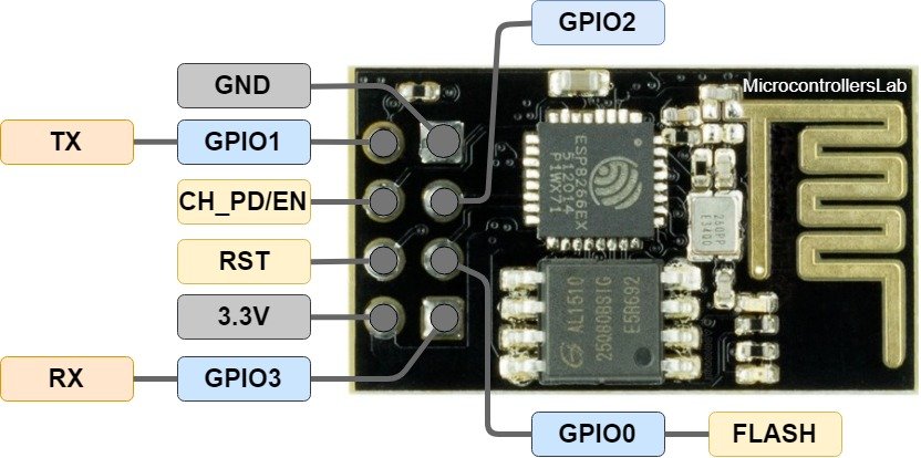
However, we will use 5 of these pins to connect with Arduino. These include the VCC, EN, GND, RX, and TX pins.
We will connect the TX (transmitter) terminal and the RX (receiver) terminal of the ESP-01 module with the digital pins of the Arduino. Software serial will be used for communicating between the two devices. Hence, we will set pin 3 for TX and pin 2 for RX in the program sketch. Therefore, TX of ESP-01 will be connected with pin 2 and RX of ESP-01 will be connected with pin 3.
The table below shows the connections that we will use to connect the two devices:
| ESP-01 | Arduino UNO |
| VCC | 5V |
| EN | 5V |
| GND | GND |
| TX | pin 2 (RX) |
| RX | pin 3 (TX) |
DC Motors with L293D Motor Driver Shield
The first step is to mount the L293D motor driver shield on the Arduino board. Then we will connect 4 DC motors with M1 (port 1), M2 (port 2), M3 (port 3), and M4 (port 4) terminals respectively.
- Connect Left side motors to M3 and M4 terminals.
- Connect Right side motors to M1 and M2 terminals.
We are using TT DC gear motors for this project. They require an operating voltage of 3-12V DC where the recommended operating voltage is 3-6V DC. Connect the positive terminal of power supply with +M terminal and negative terminal with GND terminal found at the EXT_PWR terminal block on the shield. Also, the power jumper is removed from the shield.
Setting up Blynk Application
We will use an Android smartphone for this project. So go to Google Play or Apple Store (if using an iPhone).

Search for ‘Blynk’ and install the application.

Open the application, it asks for to Sign Up: you can Sign In using Facebook or by using Gmail ID. Select New Project and then enter the project name, select device name and select connection type.

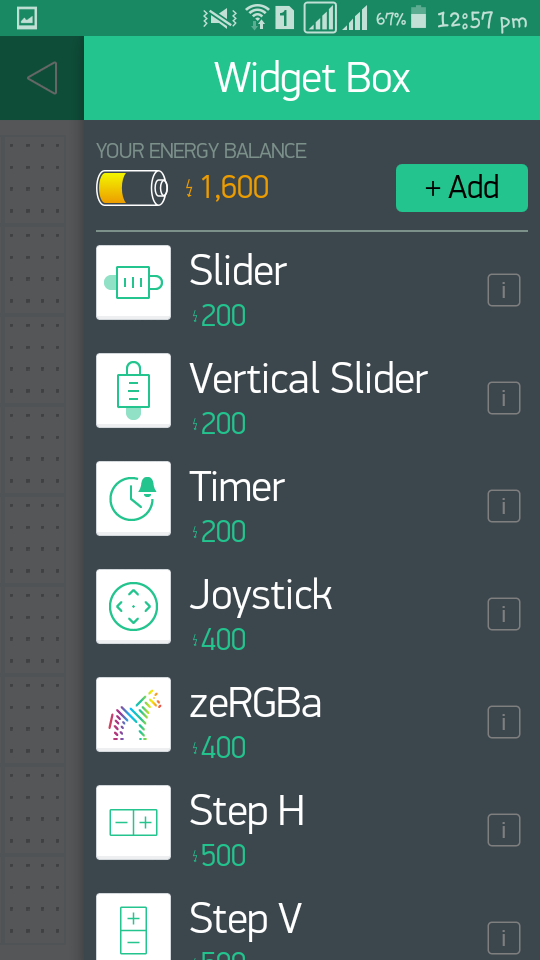
Go to Widget Box and select Joystick from the list.

Then go to the Project Settings by pressing the Nut icon. Then select the ‘Email all’ option. This will send the authorization token to our registered email.

Go to the Joy Stick setting and select the V1 variable

WiFi Controlled Robot Working
As you already noticed that we are using a joystick widget to control the robot’s motion. The user will drag the joystick in different directions: up, down, left, right and the robot will move accordingly. If the joystick remains untouched i.e. in the center position, then the robot will stop. The x and y values of the joystick constantly change as we drag it along. These values will be sent from the Blynk application to the Arduino board via WiFi. We will program our board in such a way that the values received from the Blynk app will get compared to predefined values set by the user. This will allow the robot to move in specific directions.
WiFi Controlled Robot using Arduino L293D Motor Driver Shield
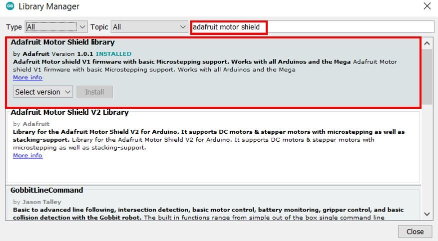
For this project, we will require the Motor Shield Library by Adafruit present in Arduino Library Manager to control the motors with our Arduino L293D motor shield. This library will provide us with useful functions to set the speed and change the direction of rotation.
To install the library, we will use the Arduino Library Manager. Open your Arduino IDE and go to Sketch > Include Libraries > Manage Libraries. Type ‘adafruit motor shield’ in the search bar and install the latest version.
Additionally, we will require ESP8266_Lib.h and BlynkSimpleShieldEsp8266.h libraries as well.
- To install the BlynkESP8266 library (ESP8266_Lib.h) for free, click here to download. This will open a GitHub page. Go to Code > Download Zip to download the zip file to your system. To add the library inside your Arduino IDE, go to Sketch > Include Library > Add .zip Library and select the zip file to add.
- To install the blynk-library (BlynkSimpleShieldEsp8266.h) for free, click here to download. This will open a GitHub page. Go to Code > Download Zip to download the zip file to your system. To add the library inside your Arduino IDE, go to Sketch > Include Library > Add .zip Library and select the zip file to add.
After installation of the libraries, restart your IDE.
WiFi Controlled Robot Arduino Code
Open your Arduino IDE and go to File > New. A new file will open. Copy the code given below in that file and save it.
#define BLYNK_PRINT Serial // Comment this out to disable prints and save space
#include <ESP8266_Lib.h>
#include <BlynkSimpleShieldEsp8266.h>
#include <SoftwareSerial.h>
#include<AFMotor.h>

SoftwareSerial EspSerial(2, 3); // RX, TX
#define ESP8266_BAUD 9600
ESP8266 wifi(&Serial);
char auth[] = "281f8675c5cc4c55a4d259ef7518d3**";

AF_DCMotor motor1(1, MOTOR12_1KHZ);
AF_DCMotor motor2(2, MOTOR12_1KHZ);
AF_DCMotor motor3(3, MOTOR12_1KHZ);
AF_DCMotor motor4(4, MOTOR12_1KHZ);

void setup()
{
  // Set console baud rate
  Serial.begin(9600);
  delay(10);
  Serial.begin(ESP8266_BAUD);
  delay(10);
  Blynk.begin(auth, wifi, "PTCL-BB", "F4C0A9AB"); // wifi username and password
}
BLYNK_WRITE(V1)
{
  int x = param[0].asInt();
  int y = param[1].asInt();
  // Do something with x and y

  if (y > 220)
    forward();
  else if (y < 35)
    backward();
  else if (x > 220)
    right();
  else if (x < 35)
    left();
  else
    Stop();
}
void loop()
{
  Blynk.run();
}


void forward()
{
  motor1.setSpeed(255);
  motor1.run(FORWARD);
  motor2.setSpeed(255);
  motor2.run(FORWARD);
  motor3.setSpeed(255);
  motor3.run(FORWARD);
  motor4.setSpeed(255);
  motor4.run(FORWARD);
}

void backward()
{
  motor1.setSpeed(255);
  motor1.run(BACKWARD);
  motor2.setSpeed(255);
  motor2.run(BACKWARD);
  motor3.setSpeed(255);
  motor3.run(BACKWARD);
  motor4.setSpeed(255);
  motor4.run(BACKWARD);
}

void left()
{
  motor1.setSpeed(255);
  motor1.run(FORWARD);
  motor2.setSpeed(255);
  motor2.run(FORWARD);
  motor3.setSpeed(0);
  motor3.run(RELEASE);
  motor4.setSpeed(0);
  motor4.run(RELEASE);
}

void right()
{
  motor1.setSpeed(0);
  motor1.run(RELEASE);
  motor2.setSpeed(0);
  motor2.run(RELEASE);
  motor3.setSpeed(255);
  motor3.run(FORWARD);
  motor4.setSpeed(255);
  motor4.run(FORWARD);
}

void Stop()
{
  motor1.setSpeed(0);
  motor1.run(RELEASE);
  motor2.setSpeed(0);
  motor2.run(RELEASE);
  motor3.setSpeed(0);
  motor3.run(RELEASE);
  motor4.setSpeed(0);
  motor4.run(RELEASE);
}
How the Code Works?
Firstly, we will include all the necessary libraries required for this project including Motor shield and Blynk libraries:
#define BLYNK_PRINT Serial // Comment this out to disable prints and save space
#include <ESP8266_Lib.h>
#include <BlynkSimpleShieldEsp8266.h>
#include <SoftwareSerial.h>
#include<AFMotor.h>
Specify the Wi-Fi serial pin with the software serial of Arduino. We are using pin 2 as RX and pin 3 as TX.
SoftwareSerial EspSerial(2, 3); // RX, TX
ESP8266 wifi(&Serial);
Thirdly, we will define the authorization key which was emailed to us through Blynk in our account through which we logged in it. Keep this key safe with you for security concerns.
char auth[] = "281f8675c5cc4c55a4d259ef7518d3**";
Next we will create four instances of AF_DCMotor called motor1, motor2, motor3 and motor4 for the 4 DC motors connected with the shield. We will specify the motor port we are connecting our motor with as the first parameter and the PWM frequency as the second parameter.
AF_DCMotor motor1(1, MOTOR12_1KHZ);
AF_DCMotor motor2(2, MOTOR12_1KHZ);
AF_DCMotor motor3(3, MOTOR12_1KHZ);
AF_DCMotor motor4(4, MOTOR12_1KHZ);
setup()
Inside the setup() function, we open the serial communication at a baud rate of 9600. Now, we will connect our board with the Blynk app by using the Blynk.begin() function. We specify four parameters. The first is the authorization key. The second is wifi. The third is the SSID and the fourth parameter is the password of the Wi-Fi.
void setup()
{
  // Set console baud rate
  Serial.begin(9600);
  delay(10);
  Serial.begin(ESP8266_BAUD);
  delay(10);
  Blynk.begin(auth, wifi, "PTCL-BB", "F4C0A9AB"); // wifi username and password
}
BLYNK_WRITE(V1)
The following lines of code use if-else if-else conditions to the control the robot’s movement. The virtual pin V1 is used to take the input from the Blynk application. We are using a joystick to control the robot’s movement hence we will get both x and y values. When we move a joystick on the left or the right side, the value of x varies. When we move the joystick up or down, the value of y varies.
To move forward we have set a condition that the y value needs to be greater than 220. Otherwise if it is less than 35 then the robot will move backwards. Similarly, if the x value is greater than 220 then the robot moves in the right direction whereas if it is less than 35 then it moves in the left direction. If none of the conditions are true then the robot stops.
BLYNK_WRITE(V1)
{
  int x = param[0].asInt();
  int y = param[1].asInt();
  // Do something with x and y

  if (y > 220)
    forward();
  else if (y < 35)
    backward();
  else if (x > 220)
    right();
  else if (x < 35)
    left();
  else
    Stop();
}
loop()
Inside the loop function we will use the Blynk.run() command to keep the connection running.
void loop()
{
  Blynk.run();
}
forward()
The forward() function will be responsible for moving the robot in the forward direction. We will use the run() method on the motor instances with ‘FORWARD’ as an argument inside it to move all the motors in the forward direction. Moreover, we also set the speed of all the motors by using the setSpeed() method on the motor instances. Here we are passing 255 as a parameter inside it. Valid parameters include 0-255 where 255 is the highest speed.
void forward()
{
  motor1.setSpeed(255);
  motor1.run(FORWARD);
  motor2.setSpeed(255);
  motor2.run(FORWARD);
  motor3.setSpeed(255);
  motor3.run(FORWARD);
  motor4.setSpeed(255);
  motor4.run(FORWARD);
}
backward()
The backward() function will be responsible for moving the robot in the backward direction. We will use the run() method on the motor instances with ‘BACKWARD’ as an argument inside it to move all the motors in the backward direction. Moreover, we also set the speed of all the motors by using the setSpeed() method on the motor instances. Here we are passing 255 as a parameter inside it. Valid parameters include 0-255 where 255 is the highest speed.
void backward()
{
  motor1.setSpeed(255);
  motor1.run(BACKWARD);
  motor2.setSpeed(255);
  motor2.run(BACKWARD);
  motor3.setSpeed(255);
  motor3.run(BACKWARD);
  motor4.setSpeed(255);
  motor4.run(BACKWARD);
}
left()
The left() function will move the robot to the left direction. This is done by moving the right side motors in a forward direction with maximum speed and stopping the left side motors. Note that we connected left side motors to M3/M4 terminals and right side motors to M1/M2 terminals.
void left()
{
  motor1.setSpeed(255);
  motor1.run(FORWARD);
  motor2.setSpeed(255);
  motor2.run(FORWARD);
  motor3.setSpeed(0);
  motor3.run(RELEASE);
  motor4.setSpeed(0);
  motor4.run(RELEASE);
}
right()
The right() function will move the robot to the right direction. This is done by moving the left side motors in a forward direction with maximum speed and stopping the right side motors. Note that we connected left side motors to M3/M4 terminals and right side motors to M1/M2 terminals.
void right()
{
  motor1.setSpeed(0);
  motor1.run(RELEASE);
  motor2.setSpeed(0);
  motor2.run(RELEASE);
  motor3.setSpeed(255);
  motor3.run(FORWARD);
  motor4.setSpeed(255);
  motor4.run(FORWARD);
}
Stop()
The Stop() function will be used to stop the robot. We will use the run() method on the motor instances with ‘RELEASE’ as an argument inside it to stop all the motors. The speed is also set to 0 in this case.
void Stop()
{
  motor1.setSpeed(0);
  motor1.run(RELEASE);
  motor2.setSpeed(0);
  motor2.run(RELEASE);
  motor3.setSpeed(0);
  motor3.run(RELEASE);
  motor4.setSpeed(0);
  motor4.run(RELEASE);
}
WiFi Controlled Robot Demonstration
To see the demonstration of the above code, upload the code to Arduino. Before uploading the code, make sure to select Arduino UNO from Tools > Board.

Also, select the correct COM port to which the Arduino board is connected from Tools > Port.
Disconnect the Rx and Tx Pins from Arduino Uno and then upload the code to the Arduino. Connect the RX and Tx to the Arduino wait few second to connect to the Wi-Fi whose SSID and password is defined in the code before.
After you have successfully uploaded your code to the development board, open the Blynk application.
Now move the joystick up/down/left/right and the robot will start moving accordingly.
Watch the video demonstration below:
You may also like to read:
- Voice Controlled Robot using Arduino and voice recognition app
- how to make obstacle avoidance robot using Arduino
- accelerometer Based Hand Gesture Controlled Robot using Xbee
- Bluetooth Controlled Robot using pic microcontroller
- PICK AND PLACE MULTI-AXIS Robotic ARM
- Line follower robot using microcontroller
Aslam o Alikum,
Sir kindly provide code for this project
Wasn’t there a app to control 6 functions on mobile using node mcu
Sir please help me..
It shows that ESP8266_lib.h does not exists
Please tell me how can i install it 🙏🙏🙏
Sir please help me i have installed the esp8266 library but is showing
: No such files or directry.
Please help me how can i solve it.
Sir please tell me which libraries i have to install ??