Adjustable firing angle control of thyristor using arduino, Hi everyone this project is about adjustable firing angle control of triac or thyristor using Arduino Uno. In this project , we have designed a circuit diagram to control the phase angle of thyristor over a complete sine wave or complete ac cycle for both negative and positive half cycle. This project has many applications like ac power control with thyristor and speed control of single phase induction motor.I have already posted a article on thyristor firing angle control circuit using analog electronics components. But in this project, I have created a adjustable firing angle with digital electronics components like Arduino. So now lets start with basic introduction of all the components which are used in this adjustable phase angle control of thyristor using arduino.
Recommended Components
The following components are used in this project or are helpful for building it with the Arduino.
| Component | How it’s used in this project | Buy on Amazon |
|---|---|---|
| Arduino Uno R3 | The main controller board that runs the firing-angle control sketch. | Check Price |
| Breadboard | Solderless board to build and prototype the control circuit without soldering. | Check Price |
| Jumper Wires | Used to make the connections between the Arduino, breadboard, and components. | Check Price |
As an Amazon Associate we earn from qualifying purchases. Prices and availability are accurate as of the date/time indicated and are subject to change.
Components used in adjustable firing angle control of thyristor
Followings are the main components used in this project.
- Zero crossing detection circuit
- Bride rectifier : It is used to convert negative half cycle to positive half cycle.
- resistors
- 4N25 optocoupler
- diodes
- Thyristor
- Arduino Uno R3
- variable resistor : It is used to control firing angle time.
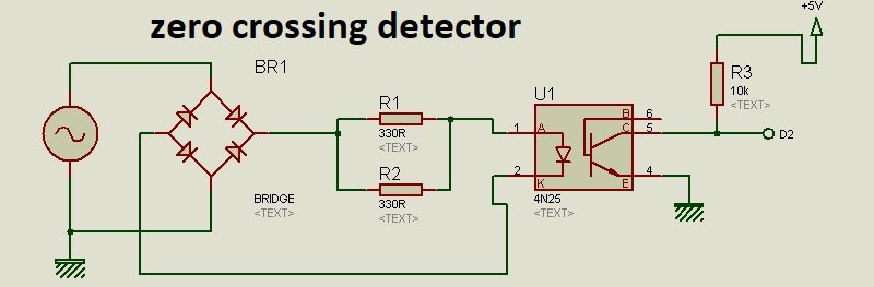
Zero crossing detection circuit
Circuit diagram of zero crossing detection circuit is shown below. Zero crossing circuit is used to detect zero crossing of ac cycle after every half cycle. Because we want to control phase angle for both positive and negative half cycles. The length of triggering pulse should be same for both positive and negative half cycle. So zero crossing detector circuit is must to design adjustable firing angle control of thyristor using arduino. 4N25 optocoupler is used for isolation between high side voltage and low side voltage and it also helps to detect zero crossing. The output of zero crossing D2 will be fed to Arduino.
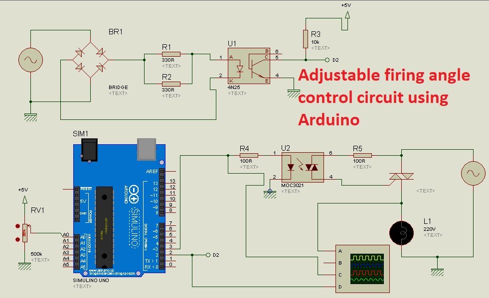
Circuit diagram of adjustable firing angle control of thyristor using arduino
- Complete circuit diagram of adjustable firing angle control of thyristor using arduino is shown below.
- In this circuit diagram variable resistor is connected with analog channel zero of Arduino.
- Variable resistor is used to adjust the firing angle of thyristor or triac.
- MOC3021 is a optically isolated thyristor or triac driver.
- Input to MOC3021 is firing pulse for thyristor which is used to turn on and turn off thyristor.
- At the output 220V AC lamp is used in series of ac power supply.
- When thyristor is off, lamp will be off and when thryistor is on, lamp will also be on.
- So the power across the lamp depends on the on time of thyristor which is ultimately depends on firing angle of thyristor
- So output power across the lamp depends on the firing angle to the triac or thyristor.
- Greater the firing angle, less will the voltage or power across the lamp as you can see in this picture.

- So firing angle is basically a reference at which thyristor will turn on. If thyristor turns on late, less voltage will appear across the device and hence less power.
- For more information check this video

please post code in C language illustrate how to AVR Atmega control SCR
Hi, can you send me the code please?
Gửi cho tôi mã điều khiển góc mở thyristor bằng adruino.
Hi, can you send me the code please?
i need code plz sir contect me
Can u provide me code of this program?
hi
very thanks
I have two questions:
1- when using an optocoupler, can it be used for many years?
(in this case, can the optocoupler retain its characteristics for many years?!)
2-isn’t it better to put current limit resistor before bridge diode?
in this case, only one terminal has a high voltage.( one head of current limiting resistor)
What Wattage resistors for R1 & R2 are you using?
Surely, they’re going to get hot!
Very nice article Thank you very much
Can i have the code please!! Thank you!!
How to 4 thyristor using .. Control lamp, rl etc load… With arduino …
Please help