In this tutorial, we will see how to interface the Hall effect sensor with Arduino. The Hall Effect sensor can detect and measure magnetic fields based on the Hall Effect phenomenon. This module is useful in many applications, such as motor control, magnetic field visualization, and position sensing using the magnetic field. The Keyes KY-003 Hall Effect Sensor module is compact and compatible with the Arduino board. We will be using this sensor for this tutorial. But, before diving deep into the details of this Hall Effect sensor module, let us look at the Hall Effect Phenomenon.
Recommended Components
The following components are used in this project or are helpful for building it with the Arduino.
| Component | How it’s used in this project | Buy on Amazon |
|---|---|---|
| Arduino Uno R3 | The main board that runs the sketch and controls all the components in this project. | Check Price |
| Hall effect sensor module | Senses magnetic fields so the Arduino can detect magnets or measure rotation. | Check Price |
| Breadboard | A solderless breadboard for prototyping and wiring the circuit without soldering. | Check Price |
| Jumper Wires | Male-to-male jumper wires to connect the Arduino to the breadboard and modules. | Check Price |
As an Amazon Associate we earn from qualifying purchases. Prices and availability are accurate as of the date/time indicated and are subject to change.
Hall Effect
The Hall effect is a phenomenon discussed in Physics. This effect is generated when a conductive material through which current is already passing is exposed to a perpendicular magnetic field. This field deflects the same type of charged carriers to one side and the opposite type of charged carriers to the other side. This separation of charges causes a potential difference, known as Hall Voltage. This Hall Voltage is proportional to the strength of the magnetic field and the current flowing through the material. The Hall effect is useful in various applications, including magnetic field sensing, current measurement, and position detection using devices like Hall effect sensors.
Note: In case this is your first project using the Arduino UNO R3, you can follow this link to learn more: Getting Started with Arduino UNO R3.
Hall Effect Sensor Module
We can use the Keyes KY-003 to detect the presence of a magnetic field and its strength using the Hall sensor. Whenever this module is placed in the magnetic field, it detects the magnetic field and provides the output. This module is useful in many projects, like a door alarm system or a speedometer. Their application is explained below.
In the door-closing alarm system, we can place the Hall sensor module on the wall, while we can place the magnet on the door handle. As soon as the magnet comes into the range of the Hall effect sensor, it will detect the change in magnetic field and control a buzzer to generate the sound or not.
The speedometer will require us to place a magnet on the wheel of our car or bike. We can attach the hall effect sensor close to the magnet. Then, by calculating the time taken by the wheel to complete a whole cycle, we can acquire speed using further calculations.
Working of Hall Effect Sensor Module
This Hall Effect sensor works on the principle of the Hall effect, which states that whenever a magnetic field is applied in a perpendicular direction to the flow of the current, a potential difference is induced. In other words, the Hall Effect is the production of a voltage difference (Hall voltage) across a current-carrying conductor or semiconductor material when it is placed in a magnetic field perpendicular to the current flow.
The Hall Effect Sensor Module typically consists of a Hall Effect sensor integrated with supporting circuitry. Here’s how it works:
Hall Effect Sensor: The core component of the module is the Hall Effect sensor, which is a small semiconductor device. It contains a thin strip of conductive material through which a constant current flows.
Magnetic Field Detection: When the Hall Effect sensor is exposed to a magnetic field, it experiences a force due to the interaction between the magnetic field and the flowing current. This force causes a buildup of charge on one side of the conductive strip and a depletion of charge on the other side, resulting in a measurable voltage difference across the sensor.
Hall Voltage Output: The voltage difference, known as the Hall voltage, is proportional to the strength of the magnetic field perpendicular to the sensor. The Hall Effect sensor generates a Hall voltage that varies with the magnetic field intensity.
Signal Conditioning: The raw Hall voltage output from the sensor is often very small and susceptible to noise. Therefore, the Hall Effect Sensor Module includes signal conditioning circuitry to amplify and stabilize the output signal.
Output Signal: Once the signal conditioning is done, the Hall Effect Sensor Module provides a usable output signal, often in the form of analog voltage or digital signal (ON/OFF) that corresponds to the strength and polarity of the magnetic field.
Applications: Hall Effect Sensor Modules are widely used in various applications, including speed sensing in motors, contactless switches, current sensing, position sensing in proximity sensors, and many other scenarios where the presence or change in a magnetic field needs to be detected.
In summary, the Hall Effect Sensor Module detects and measures the presence and intensity of magnetic fields by utilizing the Hall Effect phenomenon. It then provides an output signal that can be used to perform different tasks based on the magnetic field information.
The Hall effect sensor which we are using in this tutorial provides a digital output but some Hall effect sensor modules also include a signal conditioning circuit that provides an analog output.
Here we have listed the hardware components we will be using in this tutorial:
- Arduino UNO board
- KY-003 Hall Effect Sensor Module
- Jumper Wires
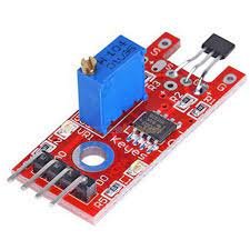
Hall Effect Sensor Module Pinout

The pinout of the hall sensor module from left to right is as follows: GND, VCC, and S. The connection of these pins with the Arduino is provided below.
| Hall Sensor Pin | Arduino UNO Board Pin |
| +5V or VCC | 5V or VIN |
| S or Signal | 2 (digital pin) |
| GND or Ground | GND |
If you want to power the module with external power, then you can give it 3.3 to 5 volts.
Interfacing Hall Effect Sensor Module with Arduino
In this section, we have provided the schematic diagram. This schematic diagram helps us properly connect our Arduino Board to the KY-003 hall effect sensor module.

The wiring schematic is very simple. We have connected the GND pin of the KY-003 Hall Effect Module to the GND pin of our Arduino Board. Then we connected the middle pin to 5V, and at last, we connected the S pin to pin 2 of our Arduino Board. These connections are in the schematic above.
Note: Now, for detection, we will use the built-in LED of the Arduino board at pin 13. This LED will turn on when a magnetic field is close to the Hall Sensor; otherwise, it will remain off.
Sketch
Open the Arduino IDE and go to File > New to create a new file. Now copy this sketch given below and paste it into the Arduino File. Select the COM port of the connected Arduino board and click Upload. This will upload the sketch to the Arduino board. If you have followed the tutorial correctly, the built-in LED will turn on when a magnet is placed near the Hall effect sensor.
const int hallPin = 2 ;     // initializing a pin for the sensor output

const int ledPin =  13 ;  // initializing a pin for the led. Arduino has built in led attached to pin 13

// variables will change :

int hallState = 0 ;    // initializing a variable for storing the status of the hall sensor.

void setup ( ) {

  pinMode ( ledPin , OUTPUT ) ;  // This will initialize the LED pin as an output pin :

  pinMode ( hallPin , INPUT ) ;   // This will initialize the hall effect sensor pin as an input pin to the Arduino :

 Serial.begin( 9600 ) ;

Serial.println ( “ microcontrollerslab.com ” ) ;

Serial.println ( “ Testing the analog hall sensor module : ” ) ;

}

void loop ( ) {

  hallState = digitalRead ( hallPin ) ;  // reading from the sensor and storing the state of the hall effect sensor :

  if ( hallState == LOW ) {   // Checking whether the state of the module is high or low

    Serial.println ( “ The state of the analog hall module is high ” ) ;

    digitalWrite ( ledPin , HIGH ) ;   // turn on the LED if he state of the module is high

  }

  else {

    digitalWrite ( ledPin , LOW ) ;   // otherwise turn off the LED :

Serial.println ( “ The state of the analog hall module is low ” ) ;

  }

}
Code Explanation
In this section, we are going to look at the above code and try to explain how each part works.
const int hallPin = 2 ;     // initializing a pin for the sensor output

const int ledPin =  13 ;     // initializing a pin for the led. Arduino has built in led attached to pin 13

// variables will change :

int hallState = 0 ;          // initializing a variable for storing the status of the hall sensor.
At first, we declare two constants for the digital pin and the built-in pin of the Arduino board as 2 and 13, respectively. Then, we declare a variable hallState and assign it an initial value of 0.
void setup ( ) {

 pinMode ( ledPin , OUTPUT ) ;      // This will initialize the LED pin as an output pin :

 pinMode ( hallPin , INPUT ) ;    // This will initialize the hall effect sensor pin as an input pin to the Arduino :

 Serial.begin( 9600 ) ;

 Serial.println ( “ microcontrollerslab.com ” ) ;

 Serial.println ( “ Testing the analog hall sensor module : ” ) ;

}
In the void setup function, we have set the pin mode of LED pin 13 as output and the hall pin as input. Then we initialized the serial monitor at a baud rate of 9600. At the end of the void setup function, we printed two lines on the serial monitor.
void loop ( ) {

  hallState = digitalRead ( hallPin ) ;  // reading from the sensor and storing the state of the hall effect sensor :

  if ( hallState == LOW ) {     // Checking whether the state of the module is high or low

    Serial.println ( “ The state of the analog hall module is high ” ) ;

    digitalWrite ( ledPin , HIGH ) ;       // turn on the LED if he state of the module is high

  }

  else {

    digitalWrite ( ledPin , LOW ) ;     // otherwise turn off the LED :

Serial.println ( “ The state of the analog hall module is low ” ) ;

  }

}
In the void loop function, we have set the digitalRead() function to continuously read hallPin and store its value in the hallState variable. Now if the value in the hallState variable is 0, it means the Hall effect sensor is detecting a magnetic field, and hence the built-in LED will turn on using the digitalWrite() function along with a line printed on the serial monitor; otherwise, the LED will remain off if no magnetic field is present in the range of the Hall effect sensor.
Output
We have provided the output of the serial monitor below:
microcontrollerslab.com
Testing the analog hall sensor module :
The state of the analog hall module is high
Conclusion
Here we have provided a summary of the topics we have covered in this tutorial:
- What is Hall Effect Phenomenon?
- Hall Effect Sensor Module and its working.
- Pinout of Hall Effect Sensor
- Schematic Diagram
- Sketch
Related Articles:
If you are interested in reading more similar articles, please check the link below:
- Interface MLX90393 Digital Hall Sensor Module with Arduino
- Hall effect sensor working, types, and applications
- TLE4999I3 Hall Effect Sensors
- ESP32 Built-in Hall Effect Sensor with Arduino IDE
So this is all about this tutorial. if you have any issues after reading this article, feel free to comment on this post. Thanks.
Experiment in “solar Panel” in Karachi.
Thank you.
Qutub
What was the output for this experiment ? Can you update the output file?