In this project, we will learn to create a contactless tachometer which is also known as the RPM meter using a pic microcontroller. A contactless digital tachometer project is designed to measure the speed of dc motor using a PIC18F46K22 microcontroller. In our previously posted article, we learned how to control the speed of dc motor using a pic microcontroller. For example, you want to extend that project with LCD display and RPM measurement option.
Tachometer or RPM Meter Introduction
So let’s start with the definition of a tachometer. A tachometer is an electrical device that is used to measure the speed of rotating machines with the help of analog or digital electronics. But digital electronics is more popular. Digital displays are among the most widely used displays for displaying different parameters. Therefore, we will be using a digital liquid crystal display to show RPM measured by digital tachometer.
There are many digital tachometers available in the market. But all these tachometers are not contactless. By contactless means, they have physical contact with the motor. But in this project, we have designed a tachometer which has no physical contact with the motor.
How to Meaure RPM of Motor?
RPM is basically a revolution per minute. That means how many rotations a motor completes in one minute. To measure the speed or RPM of the dc motor, we should measure the number of revolutions it completes per second. After that by multiplying this value with 60, we can get RPM easily.
Contactless tachometer main components
Followings are the major components of contactless digital tachometer using pic microcontroller:
LCD: Liquid crystal display is used to display speed measured by a tachometer. So if you want to make this project. You should know how to interface LCD with pic microcontroller.
PIC18F46K22 microcontroller: This microcontroller is the heart of this project which performs all calculations to measure speed and display measured on LCD. It is also used to drive dc motor by applying Pulse width modulation to a transistor which is used as a switch and it is used to drive dc motor. We have used an external oscillator with pic microcontroller.
Optical infrared sensor: optical infrared sensor is used as a contactless sensor used in this digital tachometer. Infrared light emitter diode emits the infrared light and photo diode absorbs infrared light. So in this project Infrared light emitted by infrared light emitter diode and photo diode is used a optical sensor to measure speed. I will explain its working in later of this article.
Contactless tachometer block diagram
Block diagram of contactless digital tachometer is shown below. All the components used in this dc motor speed measurement are explained above.

Contactless tachometer working
As I discussed earlier there is no physical contact between in and optical sensor. Optical sensor consists of infrared light emitting diode and photo diode. As shown in figure below, both diodes are in front each other. When light emitted by infrared light emitting diode falls on photo diode, output of optical sensor remains zero. But when no light falls on photo diode, output of optical sensor becomes high. So we contact a piece of black small paper with motor shaft. When this paper comes between infrared light emitting diode and photo diode, output become high otherwise output remains zero. So we will get pulse on every revolution of motor.

As shown in above diagram whenever black piece of paper comes between photo diode and infrared diode, no light falls on photo diode and we get high pulse at the output of optical sensor otherwise output remains zero. so we get pulse once per revolution of motor.
so we need to measure these pulses to measure speed of dc motor or any rotating machine. To measure pulses we have used timer zero of pic18f46k22 microcontroller as a counter. when we use timer as a counter, counter increment on very positive or negative edge of pulse. we can configure it in any direction. For example we are using counter to increment on positive edge. So we will get one positive edge once per revolution of dc motor. So the number of times counter counts in one second is equal to speed of dc motor in revolution per second. We can convert it into minutes by multiplying it with 60. So this is a easy way to design contactless tachometer using pic microcontroller.
How to use timer as a counter to measure speed
we are using PIC18F46K22 microcontroller. It has four timers but we are using timer zero as a counter. To use timer as a counter, we have to adjust following bits of timer zero control register.

All the bits of timer zero control register are clear. But to use it as counter T0CS set equal to one.
if T0cs = 0 // timer will be used as a timer
if T0cs= 1 // timer will be used as a counter.
Rest of the things are explained very well in above picture. Circuit diagram of digital contactless tachometer is given below.
Video lecture contactless digital tachometer
Contactless tachometer circuit diagram
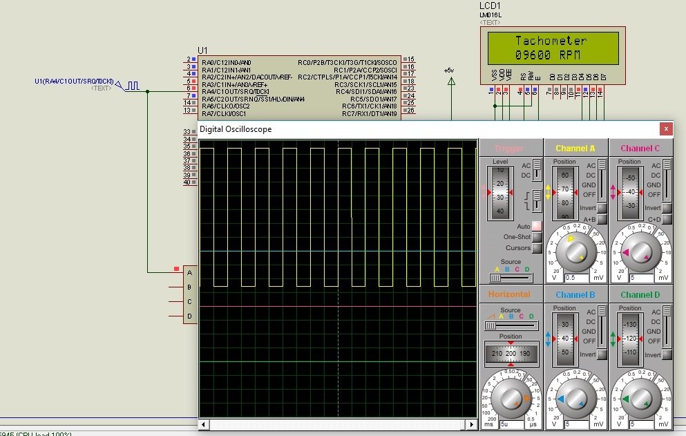
Speed measurement circuit is given below. output of optical sensor is connected with RA4/T0CLK pin which is input of timer zero when it is used as a counter. Pulse width modulation is used to change speed of dc motor. So we are using CCP1 module of PIC microcontroller. For simulation purpose we are using pulse generator in Proteus instead of actual circuit. Rest of the circuit is self explanatory.
Digital contactless tachometer code
 unsigned long speed;
 sbit LCD_RS at RD0_bit;
 sbit LCD_EN at RD1_bit;
 sbit LCD_D4 at RD2_bit;
 sbit LCD_D5 at RD3_bit;
 sbit LCD_D6 at RD4_bit;
 sbit LCD_D7 at RD5_bit;
 sbit LCD_RS_Direction at TRISD0_bit;
 sbit LCD_EN_Direction at TRISD1_bit;
 sbit LCD_D4_Direction at TRISD2_bit;
 sbit LCD_D5_Direction at TRISD3_bit;
 sbit LCD_D6_Direction at TRISD4_bit;
 sbit LCD_D7_Direction at TRISD5_bit;
 char text2[] = "digital tachometerTachometer";
 char text1[12];
 void main() {

 ANSELD=0x00;
 ANSELA=0X00;
 TRISD = 0x00;
 PORTA=0x00;
 TRISA = 0b00010000;
 T0CON = 0b00101000; // TMR0 as 16-bit counter
 Lcd_Init(); // Initialize LCD
 Lcd_Cmd(_LCD_CLEAR); // CLEAR display
 Lcd_Cmd(_LCD_CURSOR_OFF); // Cursor off
 Lcd_Out(1,4,text2); // Write message1 in 1st row
 do {
 T0CON.TMR0ON = 1;
 TMR0L = 0;
 TMR0H = 0;
 Delay_ms(1000); // Wait for 1 sec
 T0CON.TMR0ON = 0; // Stop the timer
 speed = (256*TMR0H + TMR0L)*60;
 inttostr(speed,text1);
 lcd_out(2,1,text1);
 } while(1); // Infinite Loop
 }
if you have any issue after reading this article, let me know with your comments
kindly show the complete proteus figure of this circuit
i am working on same project with pic18f45k50 controller . But the speed measurement is not happening properly. Pls help me
sir, i want same project but by using PIC16F877A controller and block diagram… please send fast….
hello sir, need your help. I am working on a similar project like this noe while using PIC18F4520. Simulatoon ok but realization is reading any speed at random. what can i do
sir can I get the same project for the PIC 18f452 , thankyou.
Need project on 8051
kindly show us the complete code please.
Measuring number of pulse per sec and multiply by 60 is useless for low speed RPM, because indication will be in step of 60. You will never find motor running at 745 RPM either you will find RPM shows 780 or 720 in between nothing it can show.(This is an example purpose only)
please send to me video how to connect with microcontroller
kindly the assembly language program for 8051 microcontroller.