MLX90393 Digital Hall Sensor module is a three-dimensional magnetic field sensor that is used for 3D position detection. The ultra-compact high-performance sensor introduced by Melexis works on the principle of the Hall effect and uses the patented Triaxis Technology. This MLX90393 IC is integrated with a high-resolution ADC and two different protocols i.e. I2C and SPI for message transmission. The device also comes with a temperature sensor and has three selectable operating modes. MLX90393 is designed as a low-power MCU-compatible sensor to detect small magnetic fields in three axes with high accuracy.
The sensor finds its applications in different DIY projects of position detection and consumer products. This tutorial shows the pinout, features, specifications, interfacing, and applications.
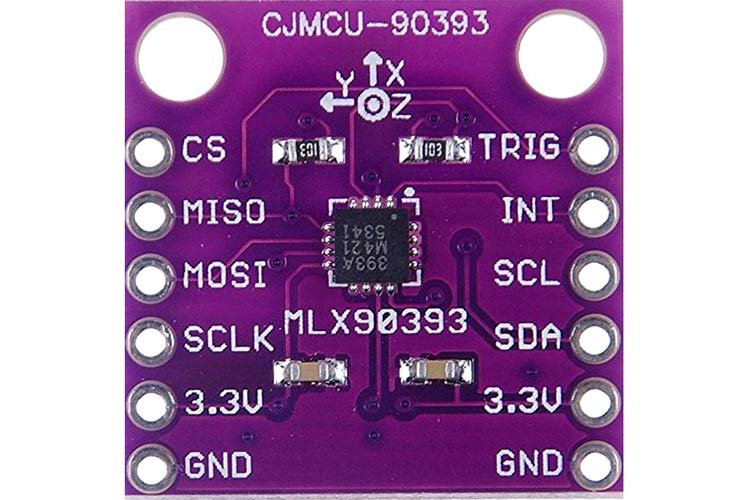
MLX90393 Pinout
The following diagram shows the pinout of the MLX90393 Digital Hall Sensor module:

Pin Configuration
MLX90393 Digital Hall Sensor module has a total of 12 pins. The pin configuration detail in tabular is mentioned below:
| Number | Pin Name | Function |
|---|---|---|
| 1 | CS | Chip Select pin |
| 2 | MISO | Master In Slave Out Data pin |
| 3 | MOSI | Master Out Slave In Data pin |
| 4 | SCLK | SPI Clock input pin |
| 5 | 3.3V | 3.3Volts Power supply pin |
| 6 | GND | Reference potential pin |
| 7 | GND | Reference potential pin |
| 8 | 3.3V | 3.3Volts Power supply pin |
| 9 | SDA | I2C Data input pin |
| 10 | SCL | I2C Clock input pin |
| 11 | INT | Interrupt pin |
| 12 | TRIG | Trigger pin |
- I2C: The Inter-Integrated Circuit protocol is provided for data communication between MCU.
- SPI: Serial Peripheral Interface is also used for serial data transmission.
- INT: The INT also functions as a data ready pin. It triggers a subroutine to read the data.
- TRIG: It is a trigger pin that also functions as an interrupt pin.
- CS: It is a chip select pin to select between SPI and I2C mode.
MLX90393 Digital Hall Sensor Features and Specifications
- Operating Voltage: 2.2 – 3.6 Volts
- Sink/Source Current: 100 uA
- Operating Temperature: -200C – 850C
- 16-bits ADC Resolution: 0.161 uT
- Full Scale Resolution: 44,000 uT
- 12C Address: 0xC0
- Serial Communication Data Rate: 10 MHz
- XYZT Triple-axial Position Output
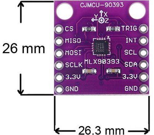
- Dimensions(LxWxH): 26mm x 26.3mm x 5mm
How does the module work?
The sensor uses the Hall effect to detect magnetic field strength and direction of the magnetic field of any object near the module.

The sensor works in three modes which are briefed as follows:
Burst Mode: The mode does the auto-sequencing of data at the maximum data rate in continuous burst mode and in non-continuous mode/standby mode only the counter operates without making an actual conversion.
Single Measure Mode: The mode makes a single conversion and then automatically moves to the Idle mode.
Wake-up Mode: Similar to the burst mode, auto-sequencing is done by comparing it to the reference point.
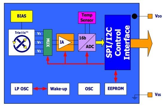
MLX90393 Digital Hall Sensor Chip Block Diagram
The block diagram of the MLX90393 Digital Hall Sensor module showing the internal circuitry of the IC is as follows:
How to interface the MLX90393 module with Microcontrollers?
As we discussed earlier, this module can provide data or communicate with a microcontroller over I2C or SPI communication bus.
Interfacing Through I2C
The interfacing diagram is provided for the visual:

For the data transmission via I2C protocol, follow these steps:
- Connect the power supply pins i.e. 3.3V and GND of the MCU and module.
- SDA and SCL of the module to the I2C interface pins of the MCU.
- Connect the INT and TRIG to the interrupts of the microcontroller unit.
- Use pull-up resistors if the microcontroller unit does not have any embedded in them.
Interfacing through SPI
The interfacing diagram is provided for the visual:

To transmit information through the Serial Peripheral Interface, the following steps must be considered:
- Connect the power supply pins i.e 3.3V and GND of the MCU and module.
- MOSI, MISO, CS, and SCLK of the module to the SPI interface headers of the MCU.
- Connect the INT and TRG to the interrupts of the microcontroller unit.
- Unlike I2C, SPI communication does not require pull-up resistors
MLX90393 Interfacing with Arduino
This section deals with the interfacing of MLX90393 magnetometer with Arduino UNO. In this tutorial, we will use I2C pins of Arduino to interface MLX90393 module through its I2C pins.
Connection Diagram
The following figures shows the connection diagram between Arduino and MLX90393 through their I2C pins.
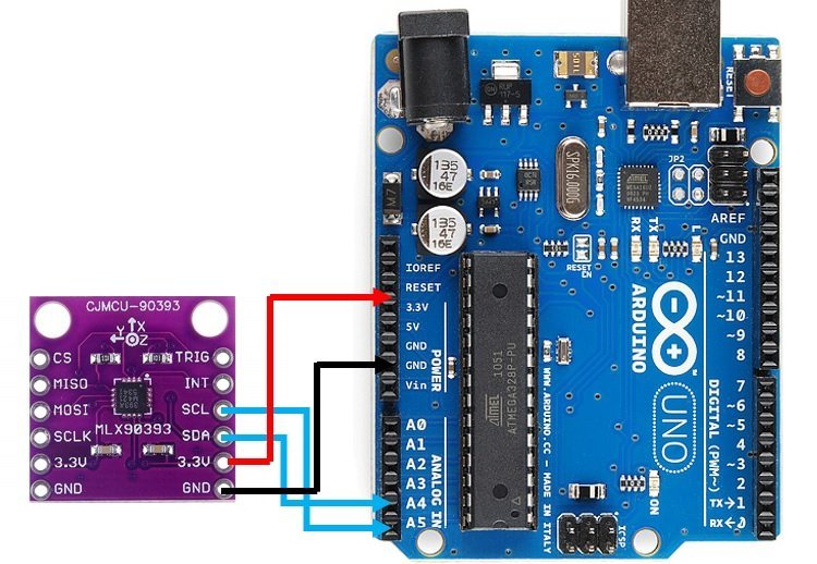
- Setup the circuit. Connect the power supply pin of the module to the 3.3V and GND of Arduino.
- Connect SDA and SCL of the module to PWM A4 and A5 of Arduino UNO to transfer data.
- Make sure to use long wires so that rest of the circuit remains undisturbed.
| MLX90393 | Arduino UNO |
|---|---|
| 3V3 | 3V3 |
| GND | GND |
| SCL | A5 |
| SDA | A4 |
Arduino Code
// Distributed with a free-will license.
// Use it any way you want, profit or free, provided it fits in the licenses of its associated works.
// MLX90393
// This code is designed to work with the MLX90393_I2CS I2C Mini Module available from ControlEverything.com.
// https://www.controleverything.com/products

#include<Wire.h>

// MLX90393 I2C Address is 0x0C(12)
#define Addr 0x0C

void setup()
{
// Initialise I2C communication as MASTER
Wire.begin();
// Initialise serial communication, set baud rate = 9600
Serial.begin(9600);

// Start I2C Transmission
Wire.beginTransmission(Addr);
// Select Write register command
Wire.write(0x60);
// Set AH = 0x00, BIST disabled
Wire.write(0x00);
// Set AL = 0x5C, Hall plate spinning rate = DEFAULT, GAIN_SEL = 5
Wire.write(0x5C);
// Select address register, (0x00 << 2)
Wire.write(0x00);
// Stop I2C Transmission
Wire.endTransmission();

// Request 1 byte of data
Wire.requestFrom(Addr, 1);

// Read status byte
if(Wire.available() == 1)
{
unsigned int c = Wire.read();
}

// Start I2C Transmission
Wire.beginTransmission(Addr);
// Select Write register command
Wire.write(0x60);
// Set AH = 0x02
Wire.write(0x02);
// Set AL = 0xB4, RES for magnetic measurement = 0
Wire.write(0xB4);
// Select address register, (0x02 << 2)
Wire.write(0x08);
// Stop I2C Transmission
Wire.endTransmission();

// Request 1 byte of data
Wire.requestFrom(Addr, 1);

// Read status byte
if(Wire.available() == 1)
{
unsigned int c = Wire.read();
}
delay(300);
}

void loop()
{
unsigned int data[7];

// Start I2C Transmission
Wire.beginTransmission(Addr);
// Start single meaurement mode, ZYX enabled
Wire.write(0x3E);
// Stop I2C Transmission
Wire.endTransmission();

// Request 1 byte of data
Wire.requestFrom(Addr, 1);

// Read status byte
if(Wire.available() == 1)
{
unsigned int c = Wire.read();
}
delay(100);

// Start I2C Transmission
Wire.beginTransmission(Addr);
// Send read measurement command, ZYX enabled
Wire.write(0x4E);
// Stop I2C Transmission
Wire.endTransmission();

// Request 7 bytes of data
Wire.requestFrom(Addr, 7);

// Read 7 bytes of data
// status, xMag msb, xMag lsb, yMag msb, yMag lsb, zMag msb, zMag lsb
if(Wire.available() == 7);
{
data[0] = Wire.read();
data[1] = Wire.read();
data[2] = Wire.read();
data[3] = Wire.read();
data[4] = Wire.read();
data[5] = Wire.read();
data[6] = Wire.read();
}

// Convert the data
int xMag = data[1] * 256 + data[2];
int yMag = data[3] * 256 + data[4];
int zMag = data[5] * 256 + data[6];

// Output data to serial monitor
Serial.print("Magnetic Field in X-Axis : ");
Serial.println(xMag);
Serial.print("Magnetic Field in Y-Axis : ");
Serial.println(yMag);
Serial.print("Magnetic Field in Z-Axis : ");
Serial.println(zMag);
delay(500);
}
Explanation of Code
To run a sketch for MLX90393, first download the library in the Arduino IDE to interface the module. Include the concerned library in the sketch.
As connections are made to communicate through the I2C interface, the setup loop initializes the Serial monitor and I2C transmission. Set all the read and write commands for the data. The chip will read data when the status byte is high. As soon as the 8-bits data is read, it writes the data into the registers. The data is converted into decimal code and displayed through the Serial monitor with a 9600 baud rate.
Upload the code. Open the Serial monitor. It will display the position of the module at that particular time in all three dimensions by measuring the magnetic field strength. Move the module in either one or all the dimensions. The serial dimensions will display the new position of the module.
Magnetic Field in X-Axis : 66
Magnetic Field in Y-Axis : 65458
Magnetic Field in Z-Axis : 8
Magnetic Field in X-Axis : 83
Magnetic Field in Y-Axis : 65477
Magnetic Field in Z-Axis : 65525
Magnetic Field in X-Axis : 76
Magnetic Field in Y-Axis : 65452
Magnetic Field in Z-Axis : 65506
Magnetic Field in X-Axis : 25
Magnetic Field in Y-Axis : 65374
Magnetic Field in Z-Axis : 65512
Magnetic Field in X-Axis : 80
Applications
- Navigation Systems
- Aerospace
- Medical Systems
- Robotics
- Joysticks
- Compass
- Defense Equipment
- Consumer products
2D Diagram
Hi, what is the unit of the magnetometer data? Is it uT?