In Tutorial 4 of LabVIEW, we will take a look at designing a Weather Station using Arduino and LabVIEW. In our last tutorial, we saw how to control the speed and direction of a DC motor using LabVIEW and Arduino and how to create a user interface in LabVIEW’s front panel. Now, for this tutorial, we will interface Arduino with LabVIEW and create a simple weather station to display the intensity of light and temperature on the front panel of LabVIEW. For this purpose, we will connect an LM35 and a light sensor for our weather station, which will measure the temperature and intensity of light in real time and, using the LabVIEW interface, display them on the panel of our weather station. We will divide our weather station project into the following steps:
Steps of Weather Station Project
This project’s steps are listed below:
- Software Requirements for a weather station.
- Hardware Requirements for the weather station.
- Circuit Wiring of weather station
- LabVIEW VI for a weather station
Software Requirement for Weather Station:
- Arduino IDE
- LabVIEW with Arduino interface installed
In case you are beginning with Arduino and LabVIEW, we recommend checking: How to Program Arduino with LabVIEW Step-by-Step Guide.

Hardware Requirement for Weather Station
- Arduino UNO Board
- LM35

Working of LM35 in Weather Station
In our weather station, LM35 is a sensor used to measure the temperature of the surrounding area. The output is actually an analog voltage, which corresponds to the surrounding temperature when multiplied by 100.
- Light-dependent resistor (LDR) :
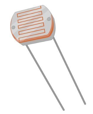
Working of LDR in Weather Station
In our weather station, a light-dependent resistor is used to detect changes in light intensity or as a light sensor. LDR is basically a variable resistor. LDR resistance changes with the intensity of light. If the intensity of light falling on LDR is high, LDR will have low resistance. When the intensity of light decreases, LDR offers high resistance. Hence, there is an inverse relationship between the intensity of light and the resistance of LDR. So the LDR is used as a light sensor.
Now the question comes to mind: how to measure resistance, which in turn can be used to calculate the intensity of light? As you know, the Arduino UNO R3 board has six analog-to-digital converter channels. All analog-to-digital converters can only measure voltage. These channels cannot measure resistance directly. But resistance can be measured indirectly by converting it into voltage. This is basically called signal conditioning. A 10K ohm resistor is used in series with the LDR through a 5-volt source. This circuit is used to convert resistance into voltage. The voltage measured across the LDR can be measured with the help of the analog-to-digital converter on the Arduino. This measured voltage can be converted back into resistance using the voltage division formula.
Circuit Wiring of Weather Station
- Jumper Wires
- Bread Board
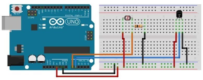
In this section, we will discuss wiring diagram of this project and show a complete circuit diagram.
| Arduino Pins | LM35 sensor pins |
|---|---|
| 5V | 1 |
| A1 | 2 |
| GND | 3 |
Connect a 10K resistor between Pin 2 and Pin 3 of the LM35 (not shown in diagram).
| Arduino pins | LDR sensor pins |
|---|---|
| 5V | 1 |
| A0 | 2 |
Also, connect a 10K resistor between the second pin of the LDR and ground.
This completes our circuit for the weather station, which measures temperature and light intensity.
LabVIEW VI for Weather Station
- Start LabVIEW.
- Create a blank VI for the weather station as in Tutorial 1.
Initializing Arduino in VI
- Go to the LabVIEW “Block Diagram” panel.
- Right-click on the white space. Go to “Arduino” and select “init”. This will add Initializations to the Arduino board.
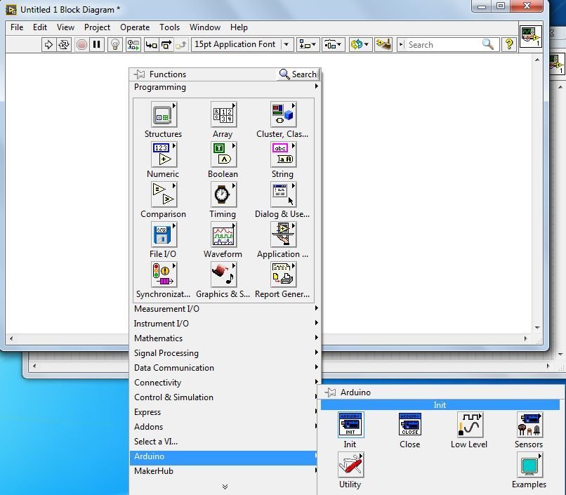
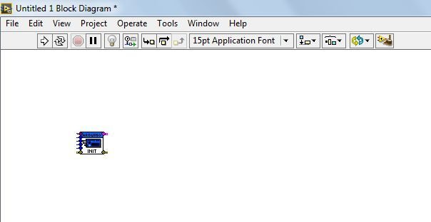
- Bring the cursor anywhere in the LabVIEW “Block Diagram” panel and place “Init”.
- The first input is “VISA resource”. It is the serial port we are using for interfacing with Arduino. We can find it in the “device manager” of the computer under “ports (COM & LPT)…”. Make sure the Arduino board is connected to the computer; otherwise, it won’t be shown. For us, the port is COM4.
- Bring the cursor to the first input of “Init” until it shows “VISA resource”. Right-click on it. Go to “create” and select “constant”. As we will be using a constant value for serial communication with the port for the weather station.

- Click on the arrow; it will show the available options. In our case, it’s “COM4”. Select the appropriate one after checking the device manager as mentioned above; otherwise, it won’t work.

- The second input is “Baud Rate”. Create it as a constant, as done for the “VISA resource”. Right-click on “Baud Rate”, go to “Create” and then select “constant”.

- The third input is “Board Type”, the fourth is “Bytes per packet”, and the fifth is “Connection Type”. We will make these constants as well.

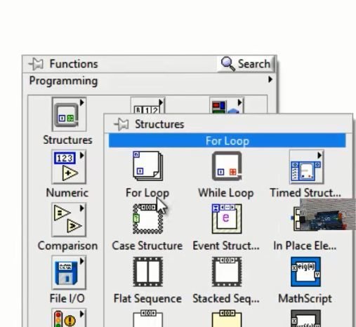
While Loop Structure
- Click on the white space on LabVIEW’s “Block Diagram” and follow “Structure → select While loop“.
- The result is as follows:

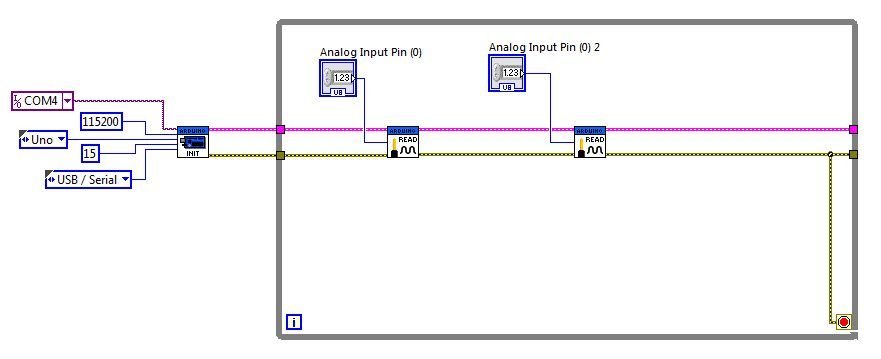
Analog Read Pins for Arduino
- Place two “Analog read pins” one by one and join the diagram as follows:

- Use “Control” to create input parameters, “Analog input pin” for both “Analog Read Pin” blocks as follows:

- This step’s output is shown below.
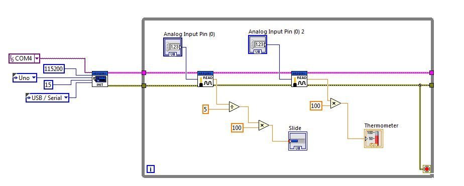
Placing Operators and constants
- Right-click on the white area. Go to “Numeric” and find “Divide”.

- Similarly, find the “Multiply” block, place it, and join them. Create the indicated “Constants” as follows:

- Create “Multiply” and “Constant” once again for the second analog input block.

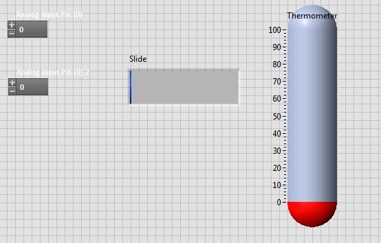
Placing Thermometer and Slide in VI
- Go to the front panel and find “Thermometer” as shown on the block diagram of LabVIEW.

- Also find “slide”, as we found the thermometer. Place both of them on the front panel, one by one.
- Join “Slide” and “Thermometer” as shown on the block diagram of LabVIEW.
- Now go to the Arduino panel by right-clicking on the block diagram. Select “Close” on the block diagram of LabVIEW.

- Now, Join the block diagram of LabVIEW as shown below.

This completes our VI of the weather station.
Uploading Program to Arduino
Now we will upload the program to Arduino and run it from LabVIEW, as shown in previous tutorials.
- Firstly, start the Arduino IDE.
- Then, click “File”, then “Open”, go through all the folders from “Computer” onward, and open the LIFA_BASE Arduino file as shown below.
- After this, upload the program opened in Arduino IDE using the Arrow button on top of Arduino IDE.
- Once uploading is done, close the Arduino IDE. It’s very important to close the Arduino IDE because both LabVIEW and Arduino use COM4. If not closed, LabVIEW will not be able to communicate, and it will crash.
- Lastly, go to the front panel. Write “0” in the LDR box and “1” in the temperature box. They indicate the Arduino pins to which LDR and LM35 are connected in real time.

- Now, run the program for the weather station in the toolbar menu of LabVIEW. The complete workings of the weather station program are shown below.
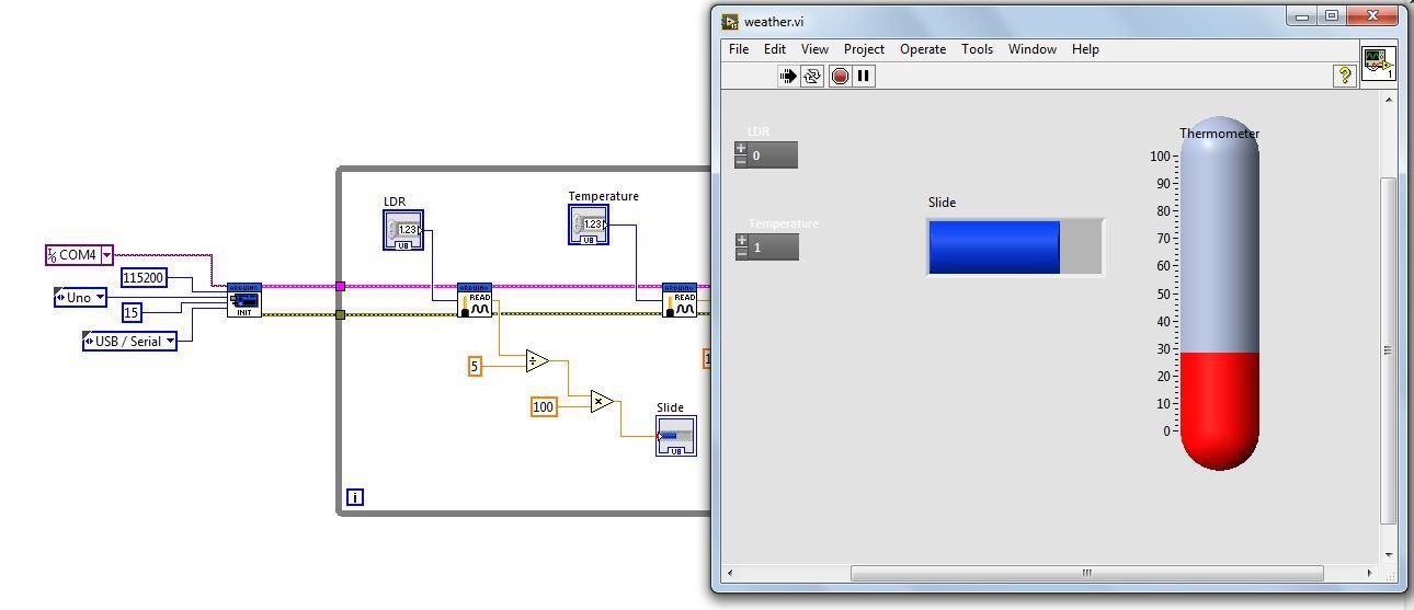
We can see the temperature and light intensity indications on the front panel of the weather station program. When we change the temperature in the real world, the thermometer shows on the panel of LabVIEW, and when the intensity of light changes, it is also indicated on the front panel of LabVIEW.
Conclusion
In this tutorial, we discussed the following topics
- Introduction and steps of weather station project.
- Software and hardware requirements.
- Circuit schematic
- LabVIEW VI program for a weather station
Related Articles
You may also like to read
- Raspberry Pi Pico W OpenWeatherMap API Sensorless Weather Station
- MicroPython: BME280 Web Server with ESP32/ESP8266 (Weather Station)
- DHT11 interfacing with Arduino and weather station
- MPLAB XC8 Compiler – Write your First Program
- Using debugging tools in LabView: tutorial 23
- Data Flow in LabView: tutorial 20
Hey please let me know how to download the lifa base code,please give the link asap
yes I too want bro…if u get pls let me know
hello
please could you provide me with the Arduino code ASAP please