In this tutorial, we will learn how to design a half-adder circuit using LabVIEW. Prior knowledge of LabVIEW is assumed, so if you’re unfamiliar with it, we recommend reviewing some introductory materials first.
For those already acquainted with digital logic design, you likely know the purpose and workings of a half-adder in the context of digital systems. In this tutorial, we will design a VI (Virtual Instrument) that accepts two logic inputs (0 or 1) from the user and returns the sum and carry when these inputs are added together. We’ll begin with a brief introduction to the half-adder, followed by the step-by-step process of designing the VI for performing the half-adder operations.
Introduction to Half-Adder Circuit
An electronic or digital circuit that performs the addition of two binary numbers and is a type of adder is known as a half-adder. Two single binary digits are added in a half-adder, and it is able to return the output with a carry value. A simple half-adder has two inputs, called A and B, and two outputs, S (sum) and C (carry). The common representation uses an XOR logic gate and an AND logic gate.
How to Design Half-Adder Circuit in LabVIEW
Let’s design a VI that will do a simple half-adder operation in LabView. First of all, create a VI as we have discussed in Tutorial 1, and save it for future use, as we have been doing in all the previous tutorials.
Now we have to set the Boolean inputs for the input values A and B to be added and the two Boolean outputs to display sum and carry. For Boolean inputs, we will use Boolean control, i.e., a push button. On the front panel, press right-click, and from the Control Palette, select Boolean, and then select Push Button, as shown in the figure below.

Place two such push buttons for two binary single-digit inputs. Now, in order to place an indicator for the binary output indication, we have to place LEDs. On the front panel, press right-click, and from the Control Palette, select Boolean, and then select Square LED as shown in the figure below.

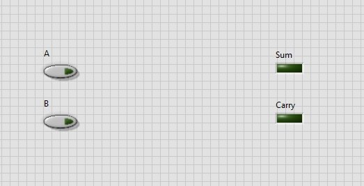
Controls and Indicators
Place two indicators to display the sum and carry on the output. The resulting controls and indicators are shown in the figure below.
Never forget to name the blocks accordingly. Now move to the block diagram for XOR and AND gate placement. From the Function Palette on the block diagram window, select Boolean and then select “Exclusive Or”, as shown in the figure below.

Summing Block
This block will return the sum of the half-adder output. At the input of this block, connect the two Boolean controls created previously, and at the output of it, connect the Boolean indicator, i.e., the square LED you created and named sum previously, as shown in the figure below.

To design the carry operation, we have to use an AND gate. From the Function Palette on the block diagram window, select Boolean and then select AND, as shown in the figure below.

Carry Block Diagram
This block will return the carry of the half-adder output. At the input of this block, connect the two Boolean controls created previously, and at the output of it, connect the Boolean indicator, i.e., the square LED you created and named carry previously, as shown in the figure below.

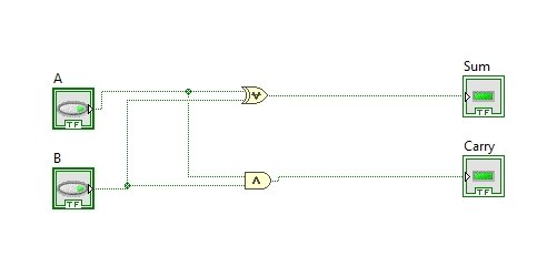
Block Diagram
The complete block diagram of a half-adder is shown in the figure below.
The output of the half adder should be according to the table given below:
| A | B | Sum | Carry |
|---|---|---|---|
| 0 | 0 | 0 | 0 |
| 0 | 1 | 1 | 0 |
| 1 | 0 | 1 | 0 |
| 1 | 1 | 0 | 1 |
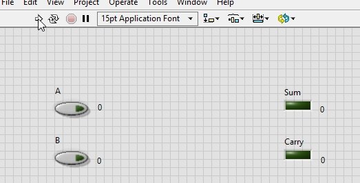
Now on the front panel, set the values of both A and B to 0 and run the VI. Both the LEDs will remain on according to the above table, as shown in the figure below.
Now change the value of A to 1 and keep the value of B to zero, and again run the VI. According to the table, the sum LED will turn ON and the carry will remain OFF, as shown in the figure below.

Now change the value of A to 0 and the value of B to 1, and again run the VI. According to the table, the sum LED will turn ON and the carry LED will remain OFF, as shown in the figure below.

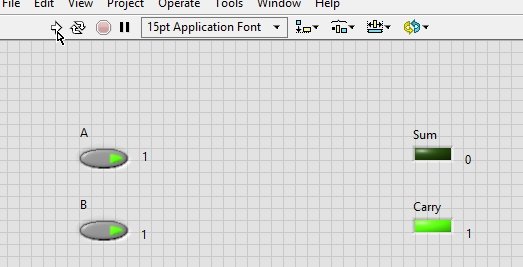
Set the values of both A and B to 1 and again run the VI. The carry LED will now turn ON, the sum LED will turn OFF, and the output will again be in accordance with the above table, as shown in the figure below.
Conclusion
In conclusion, this tutorial provides an in-depth overview of designing a half-adder circuit in LabVIEW’s VI. It also covers a step-by-step procedure explanation of each part of the example in detail. This helps us better understand the concept of designing a half-adder circuit in LabVIEW’s VI. You can utilize and improve this tutorial’s concept to design a full adder circuit in LabVIEW as well. Hopefully, this tutorial was helpful in expanding your knowledge of LabVIEW
You may also like to read
- ESP32 BLE Server GATT Service Battery Level Indication
- ESP32 Bluetooth Low Energy (BLE) using Arduino IDE
- STM32 DMA Tutorial How to Use Direct Memory Access (DMA) in STM32
- MLX90614 Non-contact Infrared Temperature Sensor with ESP32
- RCWL-0516 Microwave Radar Sensor Module with ESP8266 NodeMCU
This concludes today’s article. If you face any issues or difficulties, let us know in the comment section below.