In this STM32 Blue Pill tutorial, we introduction of DMA direct memory access controller of STM32 microcontrollers. We will discuss the hardware and features of the DMA unit, how to configure and use it and its applications.
Recommended Components
The following components are used in this project or are helpful for getting started with STM32 Blue Pill development.
| Component | How it’s used in this project | Buy on Amazon |
|---|---|---|
| STM32F103C8T6 Blue Pill Board | The STM32 board whose DMA controller is covered in this guide. | Check Price |
| ST-Link V2 Programmer | SWD programmer/debugger used to flash code onto the Blue Pill. | Check Price |
| Breadboard & Jumper Wires | For prototyping peripheral connections while testing DMA. | Check Price |
As an Amazon Associate we earn from qualifying purchases. Prices and availability are accurate as of the date/time indicated and are subject to change.
DMA Introduction
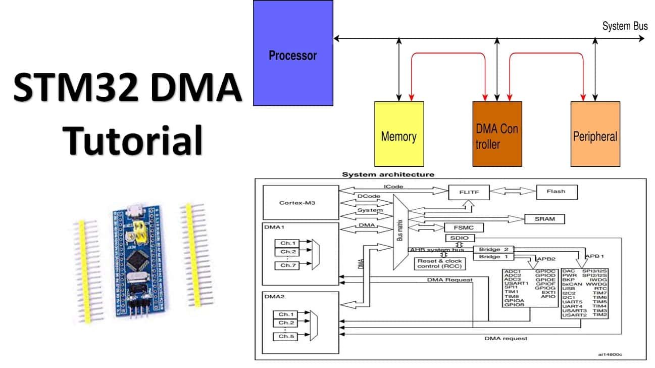
Direct Memory Access typically known as DMA is a data transfer technique in which I/O devices communicate directly with the memory without passing through the Central Processing Unit. In this hardware mechanism, a DMA controller is a digital logic unit in the computer architecture that substitutes the CPU unit and is responsible for accessing the input-output devices and memory for transferring data. It therefore takes off the load of operations related to memory transfers, thereby causing a vast reduction in the CPU load.
A DMA controller is a dedicated hardware that performs read and write operations directly without the involvement of the CPU and saves time that involves opcode fetching, decoding, incrementing, and source/destination test addresses that otherwise, central processing units should do. This leads to high data transfer rates between the peripherals and the memory and communicates large blocks of data speedily.
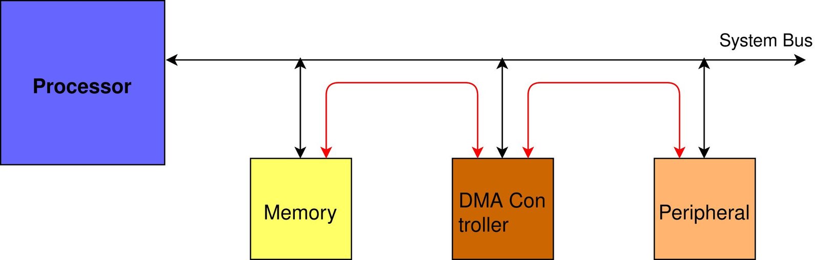
A CPU without a DMA unit may suffer from overload and cause it overwork as the main processor is responsible for transferring data to and from peripherals and memory along with code executing and acquiring instructions. To make sure the CPU works to its full potential, the process of data transfer is given off to the DMA unit so as to decrease the load of the main processor.
STM32 Blue Pill System Architecture showing DMA unit
The diagram below shows the system architecture of STM32F103C8T6 microcontroller which comes with STM32 Blue Pill.
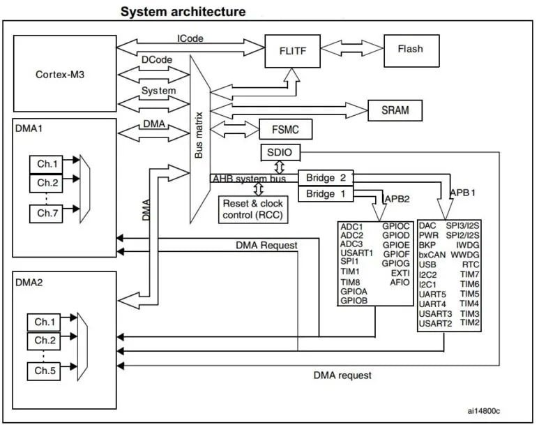
Note in the diagram above that by incorporating a DMA unit, the data stream from any of the peripherals eg ADC1 or USART1 can now be directly sent to the SRAM without the intervention of the main processor. The CPU can continue doing its own tasks thereby increasing the productivity of the system. Although not always advantageous, the DMA unit may pose some issues as well.
The DMA unit shares the system bus with the Cortex-M3 core that enables it to accomplish direct memory transfer. The bus matrix uses round-robin scheduling which makes sure that the CPU has access to minimum half of the system bandwidth. The bus matrix implements round-robin scheduling, thus ensuring at least half of the system bus bandwidth (both to memory and peripheral) for the CPU in cases when the DMA stops the CPU access to the system bus which happens when both the DMA and the main processor have the same target destination.
In short, the DMA unit frees the CPU and allows it to perform other operations. Without any CPU intervention, a fast data transfer occurs between peripherals and memory as well as memory to memory with the aid of the DMA unit.
STM32 Blue Pill DMA Hardware
As you may see in the system architecture below, the STM32F103C8T6 has 2 DMA controllers (DMA1 and DMA2). DMA1has 7 channels and DMA2 has 5 channels. Furthermore, each channel has dedicated resources for managing memory access requests from one or more peripherals which means it has a total of 12 channels which can be used with different peripherals to directly transfer between memory and peripherals. We can also use each DMA channel with one or more peripherals to handle memory transfer requests. To do so, it provides an arbiter which sets the priority for DMA requests.
Key Features
Below we have listed some key features of the DMA unit of STM32 Blue Pill:
- The STM32 Blue Pill features twelve channels that can be configured for DMA requests. This includes seven for DMA1 and five for DMA2
- All channels have their own DMA hardware requests and software triggers which are easily configurable by software.
- The DMA requests also feature priorities in four levels of very high, high, medium and low which can be set through software. They are configured in the DMA_CCRx register. Incase, of hardware, it features equality where the channel with the lower number gets priority over the one with the higher number. The arbiter is responsible for monitoring the channel requests according to the set priority. After that it will initiate the peripheral or memory access sequences.
- It features emulating packing/unpacking, self-reliant source and destination transfer which includes byte, half-word and word.
- Circular Buffer Management
- Features memory to memory, peripheral to peripheral, peripheral to memory and memory to peripheral transfer
- Has the ability to access flash, SRAM, APB1, APB2 and AHB peripherals, both as a source and as a destination.
- Maximum 65536 number of programmable data can be transferred through the DMA unit
- Each channel has three event flags which include DMA half transfer, DMA transfer complete and DMA transfer error for a single interrupt request. These flags enable flexibility as there are individual interrupt enable bits.
Data Handling in DMA
In this section, we will look at how the DMA unit performs the data transactions. There are mainly three operations that dictate the data handling/transfer process.
- Firstly, the data is loaded from the peripheral data register or a particular place in the memory. It is directed through the internal current peripheral or memory address register. Here, for the first transfer, the start address is the base memory or peripheral address which is programmed in the DMA_CPARx/DMA_CMARx register.
- Secondly, the data is stored which got loaded to the peripheral data register or a particular place in the memory that was directed through the internal current peripheral or memory address register. Here, for the first transfer, the start address is the base memory or peripheral address which is programmed in the DMA_CPARx/DMA_CMARx register.
- Thirdly, the DMA_CNDTRx register is post decremented. This register holds the number of data transfers that are left.
DMA Channels
As mentioned previously, STM32 Blue Pill features twelve independent DMA channels which are able to monitor DMA transfers between a memory address and a peripheral address found at a particular address. Maximum 65535 number of programmable data can be transferred by the DMA unit. After the transaction takes place, the register holding the number of data gets decremented.
The DMA_CCRx register contains the PSIZE/MSIZE bits that enable the transfer data sizes of the peripheral/memory to be programmed easily. Depending on the PINC/MINC bits present in the DMA_CCRx register, the peripheral/memory pointers can be set to be post incremented after each transaction occurs. In case the incremented mode is enabled, then the address of the next transfer will be the address of the previous one incremented by 1, 2, or 4 according to the set data size.
The DMA request can be set up in circular mode where continuous data transfer occurs, the number of data which is to be sent continuously reloads according to the initial value set in the channel configuration phase, and the DMA requests continue to work endlessly. To enable circular mode, the CIRC bit present in the DMA_CCRx register is used.
However, the DMA request can also be set up in memory to memory mode. In this case, the DMA channels are not triggered by a request from a peripheral. It is not simultaneously used with circular mode.
DMA Request Mapping
The table below shows the DMA1 requests for each channel from channel 1 to channel 7.
| Peripherals | Channel 1 | Channel 2 | Channel 3 | Channel 4 | Channel 5 | Channel 6 | Channel 7 |
| ADC1 | ADC1 | _ | – | – | – | – | – |
| SPI/I2S | – | SPI1_RX | SPI1_TX | SPI2/I2S2_RX | SPI2/I2S2_TX | – | – |
| USART | – | USART3_TX | USART3_RX | USART1_TX | USART1_RX | USART2_RX | USART2_TX |
| I2C | – | – | – | I2C2_TX | I2C2_RX | I2C1_TX | I2C1_RX |
| TIM1 | – | TIM1_CH1 | – | TIM1_CH4 TIM1_TRIG TIM1_COM | TIM1_UP | TIM1_CH3 | – |
| TIM2 | TIM2_CH3 | TIM2_UP | – | – | TIM2_CH1 | – | TIM2_CH2 TIM2_CH4 |
| TIM3 | – | TIM3_CH3 | TIM3_CH4 TIM3_UP | – | – | TIM3_CH1 TIM3_TRIG | – |
| TIM4 | TIM4_CH1 | – | – | TIM4_CH2 | TIM4_CH3 | – | TIM4_UP |
To activate or deactivate the peripheral DMA request, the DMA control bit present on the registers of the particular peripheral will have to be programmed.
STM32 Blue Pill DMA Configuration
In this section, let us look at how to configure the DMA unit in STM32 Blue Pill. It follows a series of steps to successfully configure the unit.
- Firstly, to configure a DMA channel, the address of the peripheral register present in the DMA_CPARx register is set. After the peripheral event occurs, the data will be transferred from/to this address to/from the memory.
- Secondly, the memory address present in the DMA_CMARx register is set next. After the peripheral event occurs, the data will be transferred from/to this address to/from the memory.
- Next, the total number of data that is to be transferred gets configured in the DMA_CNDTRx register. The value in the register decrements whenever a data transaction occurs.
- The priority of the channel is set in the DMA_CCRx register through the PL[1:0] bits.
- After that the mode of the DMA request is configured along with the data transfer direction, interrupt type, peripheral/memory data size etc. in the DMA_CCRx register.
- Finally, the enable bit for the particular channel in the DMA_CCRx register is set to initiate it.
- After enabling the DMA channel, the DMA request is started from the peripheral that is connected with the configured channel. An interrupt is triggered when half of the data bytes are sent in the case if the HTIE (half transfer interrupt enable) is enabled and marks the setting of the half transfer flag. In the case, if the TCIE ( transfer complete interrupt enable) is enabled, then an interrupt is triggered after all the data is transferred and marks the setting of the transfer complete flag.
You can refer to these STM32 tutorials where we used DMA with ADC, I2C and SPI: