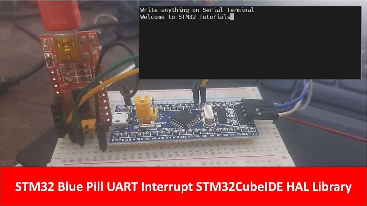
In this tutorial, we will show you how to use STM32 Blue Pill UART in interrupt mode to transmit and receive data. We will use STM32 CubeIDE to create a project where we will use UART interrupt of STM32 Blue Pill to receive data on the Rx pin via interrupt and we will send serial data through a serial terminal by using a USB-TTL converter. As soon as STM32 receives data, it will transmit it back to the serial terminal to display.
As opposed to the polling method where data reception occurs in blocking mode, in UART interrupt mode it is the opposite. The data reception occurs in the background with non-blocking mode. Here, however, a callback function is called after the data reception finishes.
Let’s create and build a project in CubeIDE to learn more!
Recommended Components
The following components are used in this project or are helpful for getting started with STM32 Blue Pill development.
| Component | How it’s used in this project | Buy on Amazon |
|---|---|---|
| STM32F103C8T6 Blue Pill Board | The STM32 board receiving UART data via interrupt. | Check Price |
| ST-Link V2 Programmer | SWD programmer/debugger used to flash code onto the Blue Pill. | Check Price |
| USB-TTL / FTDI Converter | Connects the Blue Pill’s UART2 to a serial terminal on your PC. | Check Price |
| Breadboard & Jumper Wires | For wiring the USB-TTL converter and programmer to the Blue Pill. | Check Price |
As an Amazon Associate we earn from qualifying purchases. Prices and availability are accurate as of the date/time indicated and are subject to change.
Why use UART Port of STM32 Blue Pill?
Whenever we work on embedded system applications development sooner or later we need to use a serial communication protocol. We often use UART/USART to transfer data between microcontroller and computer for various purposes. One of the most important applications is to display data on the serial console of the computer for debugging or logging important events during program execution on a microcontroller. Furthermore, many wireless devices such as GSM, GPS, Bluetooth, Xbee, LoRA, and many others provide a serial interface to transfer data between these devices and a microcontroller.
In a previous tutorial, we looked upon Blue Pill UART Communication and how to send and receive data using the polling method:
Difference Between Interrupt and Polling Method
As we have seen in the last STM32 Blue Pill UART tutorial, In the polling method, microcontroller will do nothing except polling the state of the RX pin. Therefore, it is kind of a waste of microcontroller processing time and resources. On the contrary, by using an interrupt-driven approach, microcontroller does not have to keep checking the status of Rx pin instead a callback will be triggered once data is received and ready to use. But if data is not available, a microcontroller can execute other parts of the code.
The difference will become more clear to you when you see the actual working of STM32 UART interrupt code in the later sections of this tutorial.
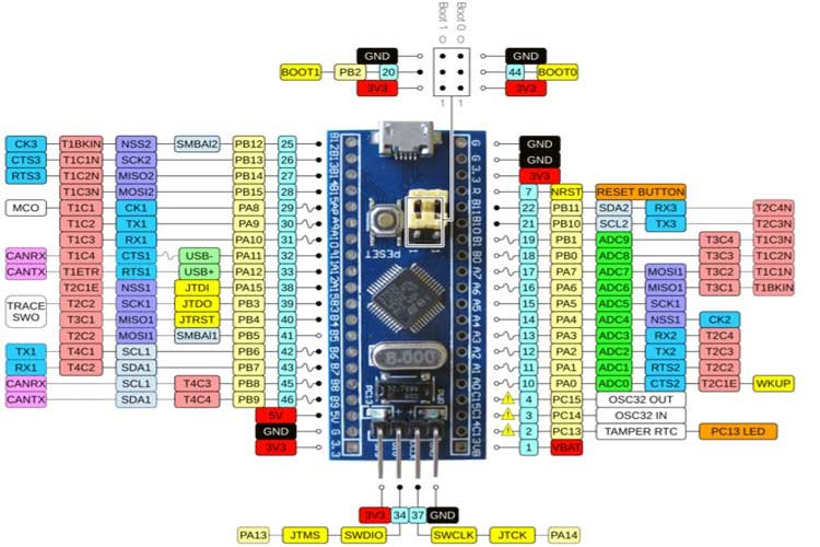
STM32 Blue Pill UART Ports
Blue Pill STM32 consists of three UART modules: UART1, UART2, and UART3.
We can use any UART module for serial data transmission. However, you may have noticed that Blue Pill STM32 microcontroller does not have an onboard ST-Link debugger therefore we will need a USB-TTL converter.
One important thing to keep in mind is that pins for UART1 and UART3 are 5V tolerant however pins for UART2 are standard 3.3V pins.
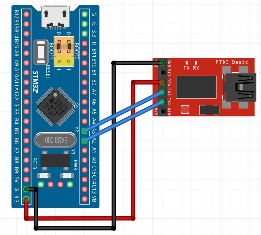
Connect FTDI USB to Serial with STM32 Blue Pill
Let us show you how to connect the FTDI programmer with Blue pill STM32.
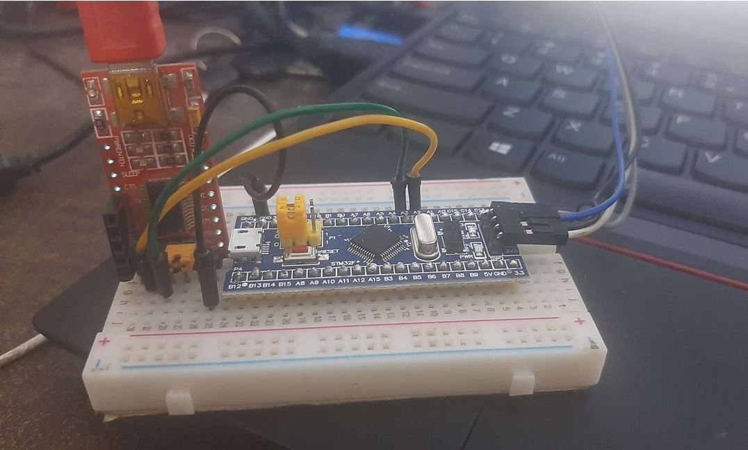
For this guide, we will use the UART2 module pins. VCC of the programmer is connected with 3.3V from the Blue pill and both the GND of the devices are connected together. PA2 is the TX2 pin of STM32 and PA3 is the RX2 pin of STM32. Connect the RX pin of STM32 with TX pin of FTDI and TX pin of STM32 with RX pin of FTDI converter.
STM32 Blue Pill UART Interrupt Example
We will use STM32Cube IDE to program our STM32 board. Open the IDE and head over to a new project.
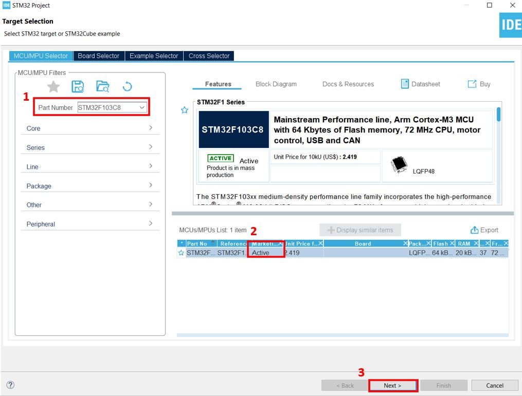
Then for the target selection, specify the STM32 Blue Pill board number. After that click on any column as shown in the picture below. Then click the ‘Next’ button.
Specify the name of your project then click ‘Finish’ to complete the setup of your project.
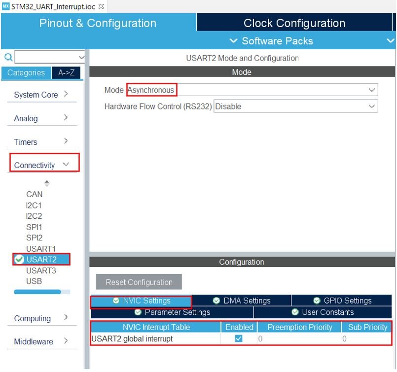
Now head over to Connectivity > USART2 and set the mode as ‘Asynchronous.’ Then head over to NVIC Settings under configuration and enable the USART2 global interrupt. This will enable UART global interrupt and also enables it in nested vectored interrupt controller (NVIC). You can learn more about NVIC here:
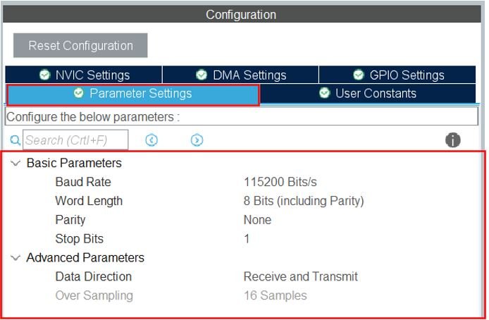
You can view the parameter settings of the UART including the baud rate, word length, parity, etc.
Now go to System Core > RCC then select ‘Crystal/Ceramic Resonator’ in from the High Speed Clock feature.
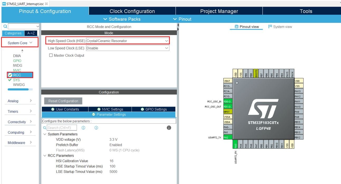
Now we have enabled the RCC external clock source.
Clock Configuration
Next, go to the Clock Configuration found at the top. This will open the following window. Here we will select the clock frequency.
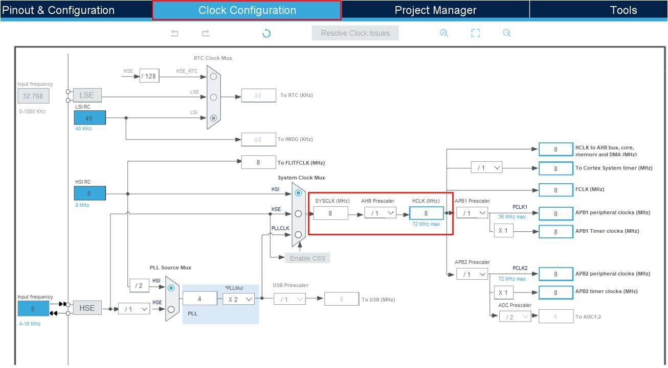
You can specify your system clock. We will set it as 72 MHz. These are the configurations we have set:

Now we will save our file. Press Ctrl + S. The following window will appear. Click ‘Yes.’ This will generate a template code for you.

Another window will appear that will ask if you want to open the perspective. Click ‘Yes.’

STM32 Blue Pill UART Interrupt Code
Now the following page opens. On the right side, you will be able to view the Outline of the code. This happened because we opened our code with perspective. In the center, you can view the main.c file. If you want to go to the Device Configuration Tool, then click the .ioc tab.

Now let us look at our main.c file that was generated.
Modifying Code
We will set up a code in which STM32 Blue Pill will echo back the received bytes to the sender using UART RX interrupt. The code will echo back whatever it will receive on the Rx pin to the terminal. In other words, whatever you type on the serial terminal, it will be sent to the STM32 Blue Pill and STM32 will transmit it back to the computer.
Inside the main.c file, look for the int main() function. Copy the code given below in the main() function.
uint8_t UART2_rxBuffer[26] = {0};

int main(void)
{
	uint8_t message[35] = {'\0'};
	uint8_t num = 0;
	char Message[] = "Write anything on Serial Terminal\r\n"; /* Message to be transmitted through UART */

  HAL_Init();


SystemClock_Config();

  MX_GPIO_Init();
  MX_USART2_UART_Init();

  HAL_UART_Transmit(&huart2, (uint8_t *)Message, strlen(Message), 10);
  HAL_UART_Receive_IT(&huart2, UART2_rxBuffer, 26);

  while (1)
  {

  }

}

void HAL_UART_RxCpltCallback(UART_HandleTypeDef *huart)
{
    HAL_UART_Transmit(&huart2, UART2_rxBuffer, 26, 100);
    HAL_UART_Receive_IT(&huart2, UART2_rxBuffer, 26);
}
How Does Code Work?
First, create a receiving buffer of 26 bytes called UART2_rxBuffer outside the main() function. This will hold the data whenever STM32 will receive data via UART interrupt.
uint8_t UART2_rxBuffer[26] = {0};UART Interrupt Call Back Function
The HAL_UART_RxCpltCallback() function is called when data reception is completed. This function is known as Rx Transfer completed callback. It takes in a single parameter ‘huart’ which is the pointer to the UART_HandleTypeDef structure containing the configuration parameter for the specified UART module. Inside this function, new data transmission and reception is initiated so that the continuity of the transmission/reception of data remains. This will ensure the data transfer occurs in a non-blocking mode.
One important point to note here is that we have specified the received buffer size (UART2_rxBuffer) and its size is 26 bytes. Therefore, this HAL_UART_RxCpltCallback function will be only triggered once Rx transfer has comletely recieved 26 bytes. But one can change it according to its requirement.
void HAL_UART_RxCpltCallback(UART_HandleTypeDef *huart)
{
    HAL_UART_Transmit(&huart2, UART2_rxBuffer, 26, 100);
    HAL_UART_Receive_IT(&huart2, UART2_rxBuffer, 26);
}
HAL UART Data Receive Interrupt Function
HAL_UART_Receive_IT() function is responsible for receiving an amount of data in non-blocking mode. This function enables UART data reception in intrrupt mode and defines size of data to be recieved.
HAL_StatusTypeDef HAL_UART_Receive_IT(UART_HandleTypeDef * 	huart,
 uint8_t * pData,
 uint16_t Size)
This function takes in three parameters.
- The first parameter is the pointer to the UART_HandleTypeDef structure containing the configuration parameters for the specified UART module.
- The second parameter is the pointer to the data buffer which holds the received data.
- The third parameter is the size of data to be received.
main.c file
This is how a complete main.c file will be after modification.
#include "main.h"

uint8_t UART2_rxBuffer[26] = {0};

UART_HandleTypeDef huart2;

void SystemClock_Config(void);
static void MX_GPIO_Init(void);
static void MX_USART2_UART_Init(void);

int main(void)
{
	uint8_t message[35] = {'\0'};
	uint8_t num = 0;
	char Message[] = "Write anything on Serial Terminal\r\n"; /* Message to be transmitted through UART */

  HAL_Init();


  SystemClock_Config();

  MX_GPIO_Init();
  MX_USART2_UART_Init();

  HAL_UART_Transmit(&huart2, (uint8_t *)Message, strlen(Message), 10);
  HAL_UART_Receive_IT(&huart2, UART2_rxBuffer, 26);

  while (1)
  {

  }

}

void HAL_UART_RxCpltCallback(UART_HandleTypeDef *huart)
{
    HAL_UART_Transmit(&huart2, UART2_rxBuffer, 26, 100);
    HAL_UART_Receive_IT(&huart2, UART2_rxBuffer, 26);
}

void SystemClock_Config(void)
{
  RCC_OscInitTypeDef RCC_OscInitStruct = {0};
  RCC_ClkInitTypeDef RCC_ClkInitStruct = {0};

  /** Initializes the RCC Oscillators according to the specified parameters
  * in the RCC_OscInitTypeDef structure.
  */
  RCC_OscInitStruct.OscillatorType = RCC_OSCILLATORTYPE_HSI;
  RCC_OscInitStruct.HSIState = RCC_HSI_ON;
  RCC_OscInitStruct.HSICalibrationValue = RCC_HSICALIBRATION_DEFAULT;
  RCC_OscInitStruct.PLL.PLLState = RCC_PLL_NONE;
  if (HAL_RCC_OscConfig(&RCC_OscInitStruct) != HAL_OK)
  {
    Error_Handler();
  }
  /** Initializes the CPU, AHB and APB buses clocks
  */
  RCC_ClkInitStruct.ClockType = RCC_CLOCKTYPE_HCLK|RCC_CLOCKTYPE_SYSCLK
                              |RCC_CLOCKTYPE_PCLK1|RCC_CLOCKTYPE_PCLK2;
  RCC_ClkInitStruct.SYSCLKSource = RCC_SYSCLKSOURCE_HSI;
  RCC_ClkInitStruct.AHBCLKDivider = RCC_SYSCLK_DIV1;
  RCC_ClkInitStruct.APB1CLKDivider = RCC_HCLK_DIV1;
  RCC_ClkInitStruct.APB2CLKDivider = RCC_HCLK_DIV1;

  if (HAL_RCC_ClockConfig(&RCC_ClkInitStruct, FLASH_LATENCY_0) != HAL_OK)
  {
    Error_Handler();
  }
}

/**
  * @brief USART2 Initialization Function
  * @param None
  * @retval None
  */
static void MX_USART2_UART_Init(void)
{

  /* USER CODE BEGIN USART2_Init 0 */

  /* USER CODE END USART2_Init 0 */

  /* USER CODE BEGIN USART2_Init 1 */

  /* USER CODE END USART2_Init 1 */
  huart2.Instance = USART2;
  huart2.Init.BaudRate = 115200;
  huart2.Init.WordLength = UART_WORDLENGTH_8B;
  huart2.Init.StopBits = UART_STOPBITS_1;
  huart2.Init.Parity = UART_PARITY_NONE;
  huart2.Init.Mode = UART_MODE_TX_RX;
  huart2.Init.HwFlowCtl = UART_HWCONTROL_NONE;
  huart2.Init.OverSampling = UART_OVERSAMPLING_16;
  if (HAL_UART_Init(&huart2) != HAL_OK)
  {
    Error_Handler();
  }
  /* USER CODE BEGIN USART2_Init 2 */

  /* USER CODE END USART2_Init 2 */

}

/**
  * @brief GPIO Initialization Function
  * @param None
  * @retval None
  */
static void MX_GPIO_Init(void)
{

  /* GPIO Ports Clock Enable */
  __HAL_RCC_GPIOD_CLK_ENABLE();
  __HAL_RCC_GPIOA_CLK_ENABLE();

}

/* USER CODE BEGIN 4 */

/* USER CODE END 4 */

/**
  * @brief  This function is executed in case of error occurrence.
  * @retval None
  */
void Error_Handler(void)
{
  /* USER CODE BEGIN Error_Handler_Debug */
  /* User can add his own implementation to report the HAL error return state */
  __disable_irq();
  while (1)
  {
  }
  /* USER CODE END Error_Handler_Debug */
}

#ifdef  USE_FULL_ASSERT
/**
  * @brief  Reports the name of the source file and the source line number
  *         where the assert_param error has occurred.
  * @param  file: pointer to the source file name
  * @param  line: assert_param error line source number
  * @retval None
  */
void assert_failed(uint8_t *file, uint32_t line)
{
  /* USER CODE BEGIN 6 */
  /* User can add his own implementation to report the file name and line number,
     ex: printf("Wrong parameters value: file %s on line %d\r\n", file, line) */
  /* USER CODE END 6 */
}
#endif /* USE_FULL_ASSERT */
Save the main.c file after modifying it. Now we are ready to build our project.
Building the Project
To build our project press Ctrl + B or go to Project > Build All.
Your project will start building. After a few moments, your project will be successfully built if there are no errors.
Connecting ST-Link Programmer with STM32
Now as we have successfully built our project let us move ahead and upload the code to our STM32 board. To do that, first we will have to connect our Blue Pill STM32 with a ST-Link programmer. We will be using ST-Link V2.

This will provide an interface between our computer and our STM32 board. It consists of 10 pins. We will be using pin2 SWDIO, pin6 SWCLK, pin4 GND, and pin8 3.3V to connect with our STM32 board. The SWDIO is the data input/output pin and the SWCLK is the clock pin. Follow the pin configuration given on the ST-LINK V2 to identify each pin.
Follow the table below to connect both devices correctly.
| STM32 | ST-LINK V2 |
|---|---|
| VCC 3.3V pin | pin8 3.3V |
| SWDIO pin | pin2 SWDIO |
| SWCLK pin | pin6 SWCLK |
| GND pin | pin4 GND |

Additionally move the BOOT jumper to the right to enable the microcontroller to go into programming mode.

Now connect your ST-LINK V2 with your computer via the USB port. Both the devices will power ON.
Next press the RUN button in the IDE. The ‘Edit configuration’ window will open up. Click ‘OK’.
After a few moments, the code will be successfully sent to the STM32 board.
Otherwise, press the RESET button on your STM32 board.
Now to bring the Blue pill back to normal mode make sure you bring the BOOT jumper back at its place.
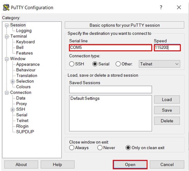
Now connect the USB to TTL serial converter with the STM32 board as mentioned previously. Open Device Manager and head over to Ports to check the COM port through which the USB-TTL converter is connected. It is COM5 in our case.

Open a terminal on your system for example Putty. Set the correct speed and COM port and then press Open to establish a connection.
Press the Reset button of STM32 and the message appears “Write anything on Serial Terminal.” Now type any characters and they will get displayed in the terminal.

You may also like to read:
- STM32 Blue Pill Timer Interrupt with STM32Cube IDE and HAL Libraries
- STM32 Blue Pill External Interrupts with STM32Cube IDE and HAL Libraries
- Push Button with STM32 Blue Pill using STM32Cube IDE – Read Digital Input Pins
- STM32 Blue Pill GPIO Pins with STM32Cube IDE: LED Blinking Tutorial
- UART Interrupt TM4C123G Tiva C LaunchPad – ARM Cortex M4
- Use UART Interrupt of Pic Microcontroller with Examples (PIC18F4550)
hi,
Thank you for these very interesting examples.
I try the 2 relative to interrupts (by push button and UART) and neither seems to work!
I suspect that the IDEcube version could be at the origine of the issue (mine Version: 1.10.1)
Could you check that please. Thank