In this Blue Pill tutorial, we will discuss how to configure STM32 timer module in encoder mode. We will use a rotary encoder to demonstrate that how to read the encoder ticks using STM32Cube IDE and HAL libraries. In the first example, we will display encoder ticks on a serial terminal, and in the second example, we will control the LED’s brightness via the rotary encoder.

Recommended Components
The following components are used in this project or are helpful for getting started with STM32 Blue Pill development.
| Component | How it’s used in this project | Buy on Amazon |
|---|---|---|
| STM32F103C8T6 Blue Pill Board | The STM32 board reading the rotary encoder in timer encoder mode. | Check Price |
| ST-Link V2 Programmer | SWD programmer/debugger used to flash code onto the Blue Pill. | Check Price |
| KY-040 Rotary Encoder | The rotary encoder whose ticks are read by the timer. | Check Price |
| USB-TTL / FTDI Converter | For displaying encoder ticks on a serial terminal over UART. | Check Price |
| 5mm LED | Brightness is controlled by the encoder in the second example. | Check Price |
| Breadboard & Jumper Wires | For wiring the encoder and programmer to the Blue Pill. | Check Price |
As an Amazon Associate we earn from qualifying purchases. Prices and availability are accurate as of the date/time indicated and are subject to change.
Introducing Rotary Encoders
A rotary encoder is such a type of encoder which is used for measuring the angular position of any rotating shaft. It determines the amount and the type of rotation. It generates an analog or digital signal depending on the rotational movement. These can be used to control the brightness of the LED, controlling the servos, and many other things. The rotary encoder has no start, middle, or end, so you can rotate it as much as you want.
On many rotary encoders, when you will move it, you will feel a bump. These are known as steps. Most have 12 steps, but they can be up to 200. There are many types of rotary encoders available which are either classified as the output signal or the sensing technology. The one we are using is the output rotary encoder and it is the simplest one. It is known as an incremental/quadrature encoder.

How do Quadrature Rotary Encoders work?
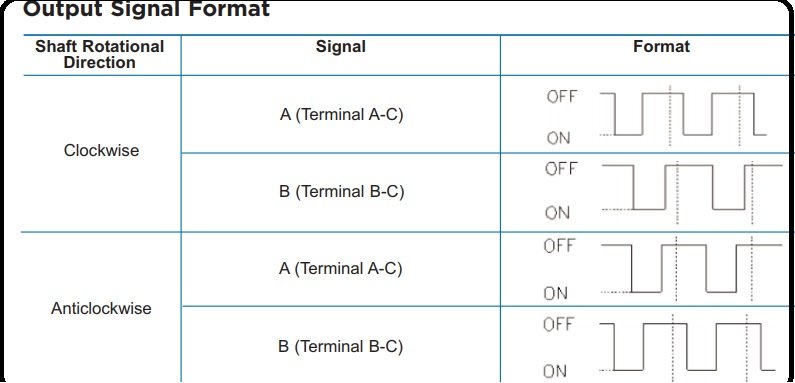
The rotary encoder gives us two square waves output (A and B) which are 90 degrees out of phase which each other. Each channel generates a particular number of equally spaced pulses per revolution also known as PPR. The number of pulses completed each turn varies. We read the value of pulse B when every time A signal pulse goes from positive to zero. When the encoder is turned clockwise, B pulse is positive and when the encoder is turned counter-clockwise, the B pulse is negative. So, we can determine the direction of turn by checking both outputs with micro-controller and by counting the number of A pulses. The direction of rotation depends upon the phase relationship of the two channels.
We can also determine the speed by counting the frequency of pulses. So, you can see that it has a lot of advantages and it is much more applications than a simple potentiometer.
Pinout
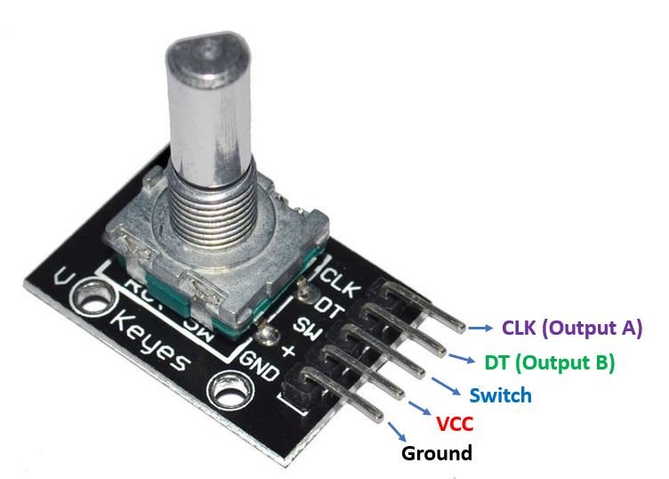
The rotary encoder module consists of five pins such as CLK, DT, SW, +, and GND.
- The GND pin is connected to ground and positive voltages are applied at + pin. These voltages should be within the range of 3.3 volts to 5 volts for normal working of this encoder.
- The SW is the switch pin that gives the output of the active low push button switch. When we push the knob of the rotary encoder from the top, the voltage goes LOW. The rotary encoder thus also acts as a push button.
- The CLK pin gives the main output pulse which is used to determine the rotation. Its output goes from HIGH to LOW (one cycle) whenever the knob of the rotary encoded is rotated by one click.
- The DT pin is also used to determine the rotation but lags the DLK by 90 degree phase shift.
- Two light emitting diodes (LEDs) are connected at pins CLK and DT with the help of two 220 ohms resistor which are connected in series with these light emitting diodes. CLK and DT pins produce square waves which are 90 degree out of phase with each other and these two square waves are used to measure clock wise and anti clock wise rotation of shaft.
STM32 Blue Pill Timer in Encoder Mode
The Blue Pill STM32F103C8 comes with four timers known as TIM1, TIM2, TIM3, and TIM4. They act as a clock and are used to keep track of time based events. The timer module can work in different configurations such as timer mode, counter mode, PWM mode, output compare mode etc. This guide focuses on configuring the timer module in encoder mode.
When configuring the STM32 Blue Pill timer module in encoder mode, the timer module works as a digital counter using two input signals. When both input pins have a valid transition, the counter gets clocked. The count pulses are generated by monitoring the sequence of the transitions of the two inputs. Not only this, but the direction of the signal is also determined. The counter counts up/down according to the sequence of the two inputs. One interesting feature of setting up a timer in encoder mode is that the encoder mode hardware support takes care of all the process of signal detection and monitoring the direction of up/down count. This makes it very simpler and easier to work with.
The timer is able to provide information about the current position of the sensor. Key parameters such as speed, acceleration/deceleration can be found by accessing this current position of the sensor. A second timer configured in capture mode along with the first timer configured in encoder mode will enable us to do that. The period between two encoder events is all that is required and it can be easily measured by setting up the two timers as mentioned above.
STM32 Blue Pill Timer Encoder Mode Project
Let’s create and build a project in STM32 CubeIDE where we will configure a timer in encoder mode and read the counter ticks as well as the push button state continuously. The data will be sent to a serial terminal on our system through UART2.
Open the CubeIDE and head over to a new project.
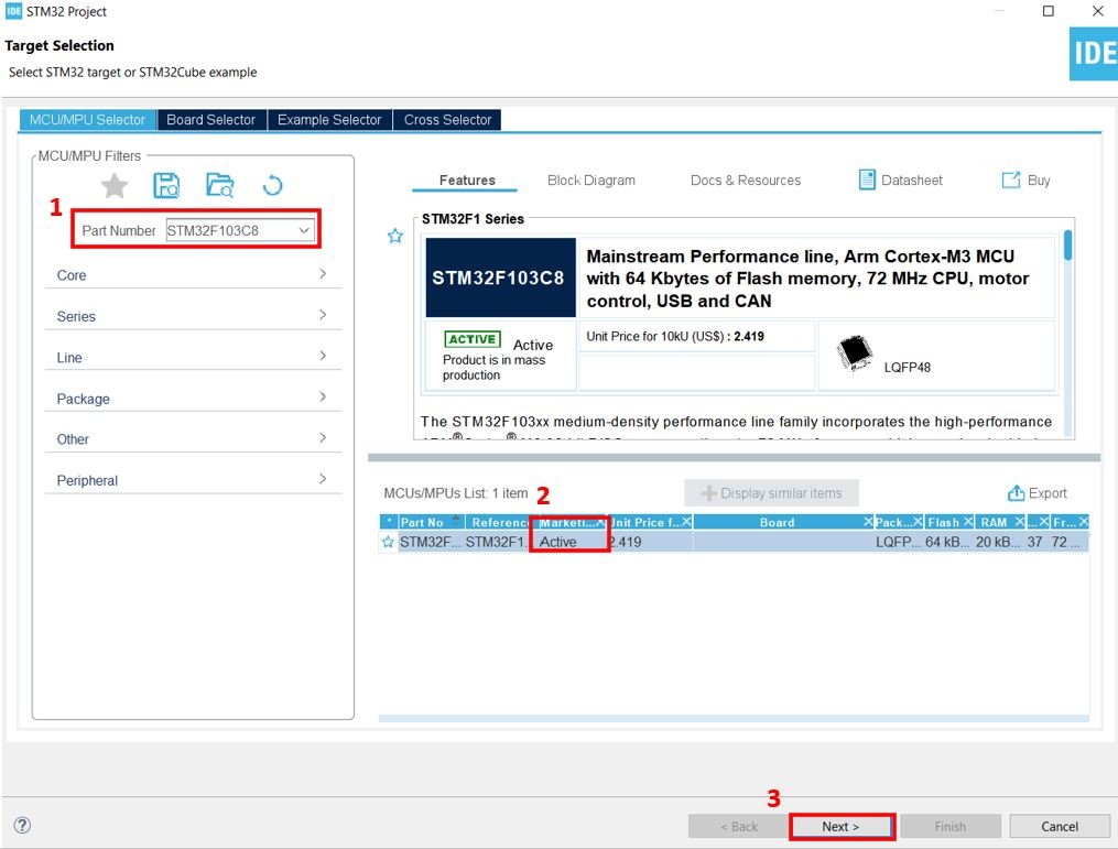
Then for the target selection, specify the STM32 Blue Pill board number. After that click on any column as shown in the picture below. Then click the ‘Next’ button.
Specify the name of your project then click ‘Finish’ to complete the setup of your project.
Setup Timer in Encoder Mode
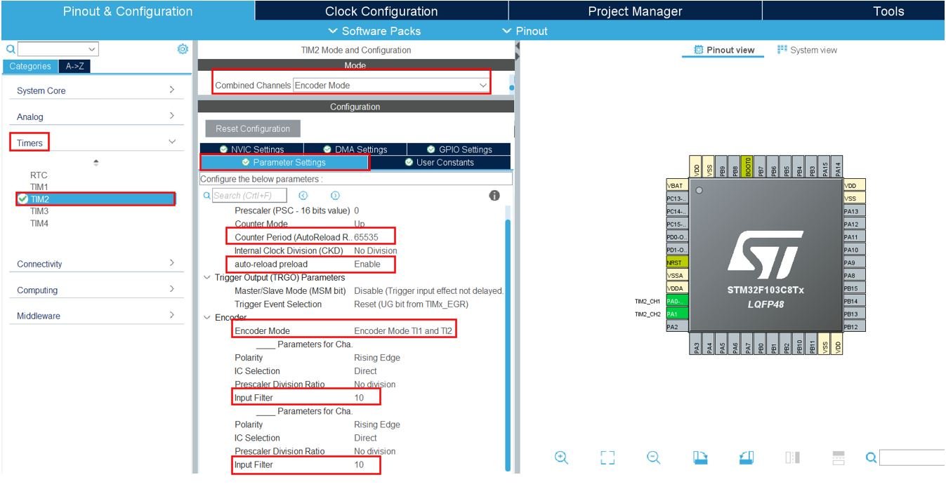
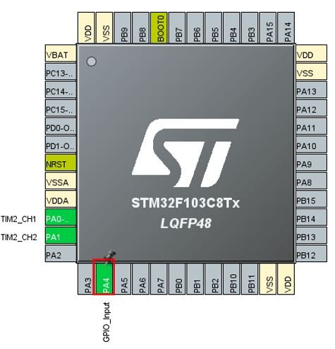
Now head over to Timers to configure the timer to work in encoder mode. We have selected Timer2. For the TIM2 mode and configuration, we have selected combined channels in encoder mode. TIM2_CH1 is PA0 and TIM2_CH2 is PA1. These two pins are the ones that will be connected with CLK Output A and DT Output B pins of the rotary encoder.
Now go to the Parameter Settings and set the counter settings. The counter period is set as 65535. The auto-reload preload is enabled. The encoder mode is set and the input filter is set as 10 to reduce any noise on the input pins.
Click at PA4 and select GPIO_INPUT. This is the input pin that will be connected with the rotary encoder’s SW pin.
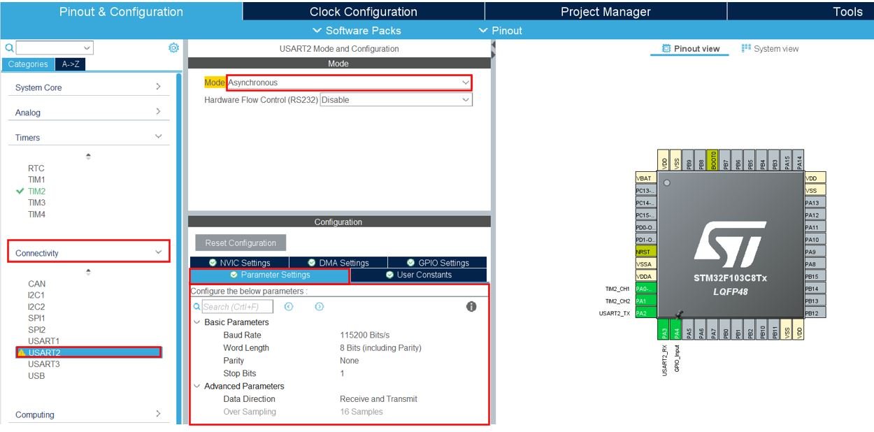
Now head over to Connectivity > USART2 and set the mode as ‘Asynchronous.’ You can also view the parameter settings of the UART including the baud rate, word length, parity, etc.
Now go to System Core > RCC then select ‘Crystal/Ceramic Resonator’ in from the High Speed Clock feature.

Now we have enabled the RCC external clock source.
Clock Configuration
Next go to the Clock Configuration found at the top. This will open the following window. Here we will select the clock frequency.
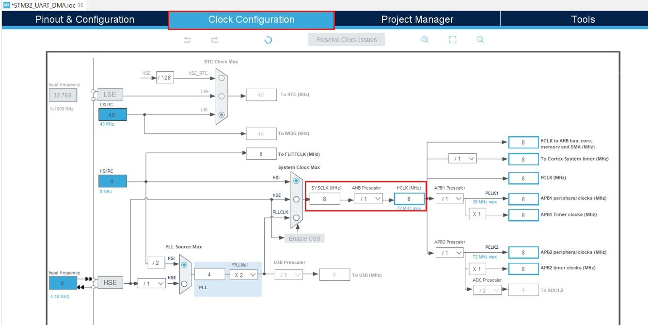
You can specify your system clock. We will set it as 72 MHz. These are the configurations we have set:

Now we will save our file. Press Ctrl + S. The following window will appear. Click ‘Yes.’ This will generate a template code for you.

Another window will appear that will ask if you want to open the perspective. Click ‘Yes.’

Simple Encoder Counter with STM32 Blue Pill Code
We will set up a code in which the Timer2 encoder counts the ticks continuously along with the state of the switch pin. We will monitor the counter values in the serial terminal by connecting our STM32 Blue Pill with an FTDI programmer using UART2 pins that we set up. The data will be printed through UART2 in the form of a string.
Now let us look at our main.c file that was generated.
Look for the MX_TIM2_Init() function.
static void MX_TIM2_Init(void)
{

  TIM_Encoder_InitTypeDef sConfig = {0};
  TIM_MasterConfigTypeDef sMasterConfig = {0};

  htim2.Instance = TIM2;
  htim2.Init.Prescaler = 0;
  htim2.Init.CounterMode = TIM_COUNTERMODE_UP;
  htim2.Init.Period = 65535;
  htim2.Init.ClockDivision = TIM_CLOCKDIVISION_DIV1;
  htim2.Init.AutoReloadPreload = TIM_AUTORELOAD_PRELOAD_ENABLE;
  sConfig.EncoderMode = TIM_ENCODERMODE_TI12;
  sConfig.IC1Polarity = TIM_ICPOLARITY_RISING;
  sConfig.IC1Selection = TIM_ICSELECTION_DIRECTTI;
  sConfig.IC1Prescaler = TIM_ICPSC_DIV1;
  sConfig.IC1Filter = 10;
  sConfig.IC2Polarity = TIM_ICPOLARITY_RISING;
  sConfig.IC2Selection = TIM_ICSELECTION_DIRECTTI;
  sConfig.IC2Prescaler = TIM_ICPSC_DIV1;
  sConfig.IC2Filter = 10;
  if (HAL_TIM_Encoder_Init(&htim2, &sConfig) != HAL_OK)
  {
    Error_Handler();
  }
  sMasterConfig.MasterOutputTrigger = TIM_TRGO_RESET;
  sMasterConfig.MasterSlaveMode = TIM_MASTERSLAVEMODE_DISABLE;
  if (HAL_TIMEx_MasterConfigSynchronization(&htim2, &sMasterConfig) != HAL_OK)
  {
    Error_Handler();
  }

}
This is the initialization function for Timer2. It configures the Timer2 on the set Prescaler, preload, counter mode, and clock frequency values.
Modifying Code
Inside the main.c file, make sure the following code is part of your script by including the lines of code given below.
int main(void)
{
  uint8_t message[50] = {'\0'};

  /* Reset of all peripherals, Initializes the Flash interface and the Systick. */
  HAL_Init();

  /* Configure the system clock */
  SystemClock_Config();

  /* Initialize all configured peripherals */
  MX_GPIO_Init();
  MX_TIM2_Init();
  MX_USART2_UART_Init();

  HAL_TIM_Encoder_Start(&htim2, TIM_CHANNEL_ALL);

  while (1)
      {
          if(HAL_GPIO_ReadPin (GPIOA, GPIO_PIN_4))
          {
              sprintf(message, "Switch Released, Encoder Ticks = %d\n\r", ((TIM2->CNT)>>2));
              HAL_UART_Transmit(&huart2, message, sizeof(message), 100);
          }
          else
          {
              sprintf(message, "Switch Pressed,  Encoder Ticks = %d\n\r", ((TIM2->CNT)>>2));
              HAL_UART_Transmit(&huart2, message, sizeof(message), 100);
          }
          HAL_Delay(100);
      }
}
Working of Code
We will first enable and start the timer in the following lines. Firstly, call MX_TIM2_Init() function to initialize Timer2 on the set Prescaler, Preload, and Clock frequency values.
Then call HAL_TIM_Encoder_Start() to start the TIM encoder interface. It takes in two parameters.
- The first parameter denotes the pointer to the TIM_HandleTypeDef structure that holds the configuration parameters for TIM module.
- The second parameter is the TIM Channels which are to be enabled. This can take either of the three values given below:
- TIM_CHANNEL_1: TIM Channel 1 is enabled
- TIM_CHANNEL_2: TIM Channel 2 is enabled
- TIM_CHANNEL_ALL: Both TIM Channel 1 and TIM Channel 2 are enabled
MX_TIM2_Init();
HAL_TIM_Encoder_Start(&htim2, TIM_CHANNEL_ALL);
Inside the while() loop, the encoder ticks is read and transmitted via UART2 to the serial terminal using HAL_UART_Transmit() after a delay of one second. We use an if-else statement to check if the switch is pressed or released. An appropriate message telling the state of the switch along with the encoder tick value will be transmitted via UART2 to the serial port terminal of our system throughout. The state of the switch pin is read using HAL_GPIO_ReadPin() function which takes in the GPIO peripheral and GPIO port bit to be read. The encoder value is read by right shifting the CNT value by 2. This will make sure that 1 tick is displayed.
  while (1)
      {
          if(HAL_GPIO_ReadPin (GPIOA, GPIO_PIN_4))
          {
              sprintf(message, "Switch Released, Encoder Ticks = %d\n\r", ((TIM2->CNT)>>2));
              HAL_UART_Transmit(&huart2, message, sizeof(message), 100);
          }
          else
          {
              sprintf(message, "Switch Pressed,  Encoder Ticks = %d\n\r", ((TIM2->CNT)>>2));
              HAL_UART_Transmit(&huart2, message, sizeof(message), 100);
          }
          HAL_Delay(100);
      }
main.c file
This is how a complete main.c file will be after modification.
#include "main.h"


TIM_HandleTypeDef htim2;

UART_HandleTypeDef huart2;


/* Private function prototypes -----------------------------------------------*/
void SystemClock_Config(void);
static void MX_GPIO_Init(void);
static void MX_TIM2_Init(void);
static void MX_USART2_UART_Init(void);

int main(void)
{
  uint8_t message[50] = {'\0'};

  /* Reset of all peripherals, Initializes the Flash interface and the Systick. */
  HAL_Init();

  /* Configure the system clock */
  SystemClock_Config();

  /* Initialize all configured peripherals */
  MX_GPIO_Init();
  MX_TIM2_Init();
  MX_USART2_UART_Init();

  HAL_TIM_Encoder_Start(&htim2, TIM_CHANNEL_ALL);

  while (1)
      {
          if(HAL_GPIO_ReadPin (GPIOA, GPIO_PIN_4))
          {
              sprintf(message, "Switch Released, Encoder Ticks = %d\n\r", ((TIM2->CNT)>>2));
              HAL_UART_Transmit(&huart2, message, sizeof(message), 100);
          }
          else
          {
              sprintf(message, "Switch Pressed,  Encoder Ticks = %d\n\r", ((TIM2->CNT)>>2));
              HAL_UART_Transmit(&huart2, message, sizeof(message), 100);
          }
          HAL_Delay(100);
      }
}


/**
  * @brief System Clock Configuration
  * @retval None
  */
void SystemClock_Config(void)
{
  RCC_OscInitTypeDef RCC_OscInitStruct = {0};
  RCC_ClkInitTypeDef RCC_ClkInitStruct = {0};

  /** Initializes the RCC Oscillators according to the specified parameters
  * in the RCC_OscInitTypeDef structure.
  */
  RCC_OscInitStruct.OscillatorType = RCC_OSCILLATORTYPE_HSE;
  RCC_OscInitStruct.HSEState = RCC_HSE_ON;
  RCC_OscInitStruct.HSEPredivValue = RCC_HSE_PREDIV_DIV1;
  RCC_OscInitStruct.HSIState = RCC_HSI_ON;
  RCC_OscInitStruct.PLL.PLLState = RCC_PLL_ON;
  RCC_OscInitStruct.PLL.PLLSource = RCC_PLLSOURCE_HSE;
  RCC_OscInitStruct.PLL.PLLMUL = RCC_PLL_MUL9;
  if (HAL_RCC_OscConfig(&RCC_OscInitStruct) != HAL_OK)
  {
    Error_Handler();
  }
  /** Initializes the CPU, AHB and APB buses clocks
  */
  RCC_ClkInitStruct.ClockType = RCC_CLOCKTYPE_HCLK|RCC_CLOCKTYPE_SYSCLK
                              |RCC_CLOCKTYPE_PCLK1|RCC_CLOCKTYPE_PCLK2;
  RCC_ClkInitStruct.SYSCLKSource = RCC_SYSCLKSOURCE_PLLCLK;
  RCC_ClkInitStruct.AHBCLKDivider = RCC_SYSCLK_DIV1;
  RCC_ClkInitStruct.APB1CLKDivider = RCC_HCLK_DIV2;
  RCC_ClkInitStruct.APB2CLKDivider = RCC_HCLK_DIV1;

  if (HAL_RCC_ClockConfig(&RCC_ClkInitStruct, FLASH_LATENCY_2) != HAL_OK)
  {
    Error_Handler();
  }
}

/**
  * @brief TIM2 Initialization Function
  * @param None
  * @retval None
  */
static void MX_TIM2_Init(void)
{

  TIM_Encoder_InitTypeDef sConfig = {0};
  TIM_MasterConfigTypeDef sMasterConfig = {0};

  htim2.Instance = TIM2;
  htim2.Init.Prescaler = 0;
  htim2.Init.CounterMode = TIM_COUNTERMODE_UP;
  htim2.Init.Period = 65535;
  htim2.Init.ClockDivision = TIM_CLOCKDIVISION_DIV1;
  htim2.Init.AutoReloadPreload = TIM_AUTORELOAD_PRELOAD_ENABLE;
  sConfig.EncoderMode = TIM_ENCODERMODE_TI12;
  sConfig.IC1Polarity = TIM_ICPOLARITY_RISING;
  sConfig.IC1Selection = TIM_ICSELECTION_DIRECTTI;
  sConfig.IC1Prescaler = TIM_ICPSC_DIV1;
  sConfig.IC1Filter = 10;
  sConfig.IC2Polarity = TIM_ICPOLARITY_RISING;
  sConfig.IC2Selection = TIM_ICSELECTION_DIRECTTI;
  sConfig.IC2Prescaler = TIM_ICPSC_DIV1;
  sConfig.IC2Filter = 10;
  if (HAL_TIM_Encoder_Init(&htim2, &sConfig) != HAL_OK)
  {
    Error_Handler();
  }
  sMasterConfig.MasterOutputTrigger = TIM_TRGO_RESET;
  sMasterConfig.MasterSlaveMode = TIM_MASTERSLAVEMODE_DISABLE;
  if (HAL_TIMEx_MasterConfigSynchronization(&htim2, &sMasterConfig) != HAL_OK)
  {
    Error_Handler();
  }

}

/**
  * @brief USART2 Initialization Function
  * @param None
  * @retval None
  */
static void MX_USART2_UART_Init(void)
{

  /* USER CODE BEGIN USART2_Init 0 */

  /* USER CODE END USART2_Init 0 */

  /* USER CODE BEGIN USART2_Init 1 */

  /* USER CODE END USART2_Init 1 */
  huart2.Instance = USART2;
  huart2.Init.BaudRate = 115200;
  huart2.Init.WordLength = UART_WORDLENGTH_8B;
  huart2.Init.StopBits = UART_STOPBITS_1;
  huart2.Init.Parity = UART_PARITY_NONE;
  huart2.Init.Mode = UART_MODE_TX_RX;
  huart2.Init.HwFlowCtl = UART_HWCONTROL_NONE;
  huart2.Init.OverSampling = UART_OVERSAMPLING_16;
  if (HAL_UART_Init(&huart2) != HAL_OK)
  {
    Error_Handler();
  }
  /* USER CODE BEGIN USART2_Init 2 */

  /* USER CODE END USART2_Init 2 */

}

/**
  * @brief GPIO Initialization Function
  * @param None
  * @retval None
  */
static void MX_GPIO_Init(void)
{
  GPIO_InitTypeDef GPIO_InitStruct = {0};

  /* GPIO Ports Clock Enable */
  __HAL_RCC_GPIOD_CLK_ENABLE();
  __HAL_RCC_GPIOA_CLK_ENABLE();

  /*Configure GPIO pin : PA4 */
  GPIO_InitStruct.Pin = GPIO_PIN_4;
  GPIO_InitStruct.Mode = GPIO_MODE_INPUT;
  GPIO_InitStruct.Pull = GPIO_NOPULL;
  HAL_GPIO_Init(GPIOA, &GPIO_InitStruct);

}

/* USER CODE BEGIN 4 */

/* USER CODE END 4 */

/**
  * @brief  This function is executed in case of error occurrence.
  * @retval None
  */
void Error_Handler(void)
{
  /* USER CODE BEGIN Error_Handler_Debug */
  /* User can add his own implementation to report the HAL error return state */
  __disable_irq();
  while (1)
  {
  }
  /* USER CODE END Error_Handler_Debug */
}

#ifdef  USE_FULL_ASSERT
/**
  * @brief  Reports the name of the source file and the source line number
  *         where the assert_param error has occurred.
  * @param  file: pointer to the source file name
  * @param  line: assert_param error line source number
  * @retval None
  */
void assert_failed(uint8_t *file, uint32_t line)
{
  /* USER CODE BEGIN 6 */
  /* User can add his own implementation to report the file name and line number,
     ex: printf("Wrong parameters value: file %s on line %d\r\n", file, line) */
  /* USER CODE END 6 */
}
#endif /* USE_FULL_ASSERT */
Save the main.c file after modifying it. Now we are ready to build our project.
Building the Project
To build our project press Ctrl + B or go to Project > Build All.
Your project will start building. After a few moments, your project will be successfully built if there are no errors.
Connecting ST-Link Programmer with STM32
Now as we have successfully built our project let us move ahead and upload the code to our STM32 board. To do that, first we will have to connect our Blue Pill STM32 with a ST-Link programmer. We will be using ST-Link V2.

This will provide an interface between our computer and our STM32 board. It consists of 10 pins. We will be using pin2 SWDIO, pin6 SWCLK, pin4 GND, and pin8 3.3V to connect with our STM32 board. The SWDIO is the data input/output pin and the SWCLK is the clock pin. Follow the pin configuration given on the ST-LINK V2 to identify each pin.
Follow the table below to connect both devices correctly.
| STM32 | ST-LINK V2 |
| VCC 3.3V pin | pin8 3.3V |
| SWDIO pin | pin2 SWDIO |
| SWCLK pin | pin6 SWCLK |
| GND pin | pin4 GND |

Additionally, move the BOOT jumper to the right to enable the microcontroller to go into programming mode.

Hardware Setup for STM32 Blue Pill Encoder Counter
We will connect a rotary encoder and an FTDI programmer with Blue pill STM32.
For this project we will require the following components:
- STM32 Blue Pill
- Rotary Encoder
- FTDI programmer/ USB to TTL converter
- Connecting Wires
- Breadboard
Connect the components as shown in the schematic diagram below:
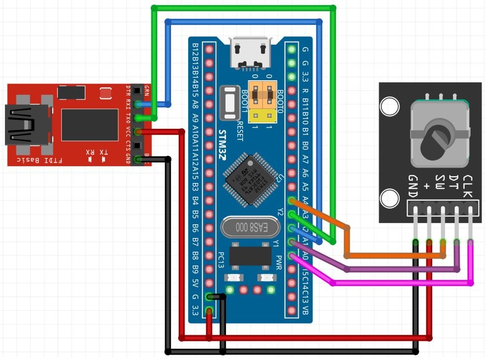
The rotary encoder module has 5 terminals which we will connect with the our Blue Pill. As the rotary encoder module requires an operating voltage in the range of 3.3-5V hence we will connect the VCC terminal with 3.3V which will be in common with the board. The CLK, DT and SW pins with PA0, PA1 and PA4 of STM32 Blue Pill respectively.
For this guide, we are using UART2 module pins. VCC of the programmer is connected with 3.3V from the Blue pill and both the GND of the devices are connected together. PA2 is the TX2 pin of STM32 and PA3 is the RX2 pin of STM32. Connect the RX pin of STM32 with TX pin of FTDI and TX pin of STM32 with RX pin of FTDI converter.
Demonstration
- Now connect your ST-LINK V2 with your computer via the USB port. Both devices will power ON.
- Next press the RUN button in the IDE. The ‘Edit configuration’ window will open up. Click ‘OK’.
- After a few moments, the code will be successfully sent to the STM32 board. Otherwise, press the RESET button on your STM32 board.
- Now to bring the Blue pill back to normal mode make sure you bring the BOOT jumper back at its place.
- Now connect the USB to TTL serial converter with the STM32 board as mentioned previously. Open Device Manager and head over to Ports to check the COM port through which the USB-TTL converter is connected. It is COM5 in our case.

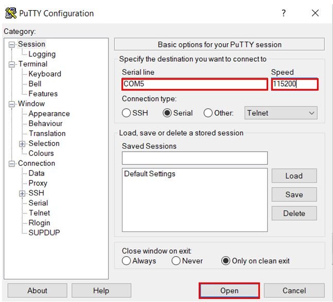
- Open a terminal on your system for example Putty. Set the correct speed and COM port and then press Open to establish a connection.
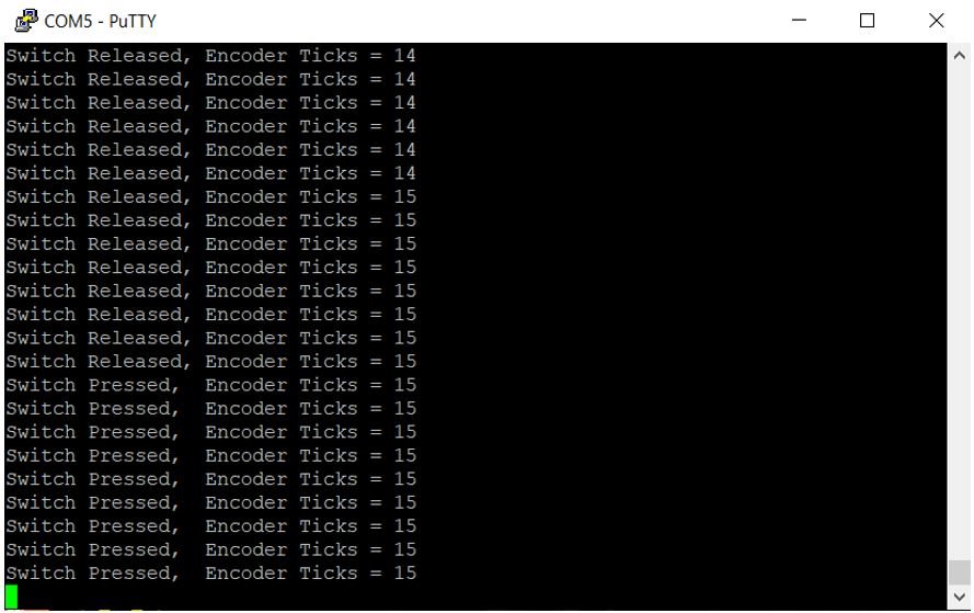
Press the Reset button of STM32. Initially, the encoder tick will be zero. Rotate the knob of the rotary encoder in both directions to see the ticks increasing or decreasing. Now press the push button and the terminal displays a message that the switch was pressed.
Video demo:
STM32 Blue Pill Rotary Encoder LED Brightness Control
Let’s create and build another project in STM32 CubeIDE where we will configure a timer in encoder mode whose values will be mapped to the PWM duty cycle which will control the brightness of an LED setup as an output pin.
So let us begin the project! Create a new project in STM32 Cube IDE and follow similar steps as before.
- Specify the target selection and then name of your project to complete the setup of your project.
- Firstly, configure Timer2 in encoder mode with combined channels TIM2_CH1 and TIM2_CH2 as we did previously.
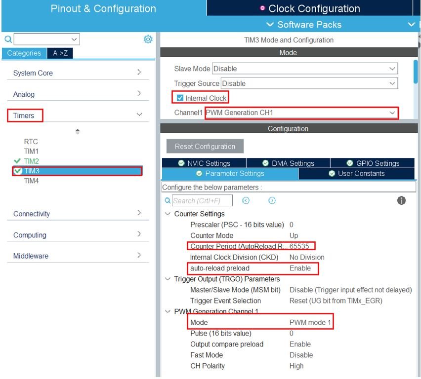
- Next, configure another timer in PWM mode. We have selected Timer3. The mode for Timer3 is set next where we configure the clock source as the internal clock and Channel 1 as PWM Generation CH1. This way Timer3 will work in PWM mode where PA6 (Timer3 Channel 1) will be set as an output. Now go to the Parameter Settings and set the counter settings. The counter period is set as 65535. The auto-reload preload is enabled. The encoder mode is set as PWM mode 1.
The rest of the steps are same as we did previously.
- Now go to System Core > RCC then select ‘Crystal/Ceramic Resonator’ in from the High Speed Clock feature. Now we have enabled the RCC external clock source.
- Next go to the Clock Configuration found at the top. This will open the following window. Here we will select the clock frequency. You can specify your system clock. We will set it as 72MHz.
Now we will save our file. Press Ctrl + S. The following window will appear. Click ‘Yes.’ This will generate a template code for you.
Another window will appear that will ask if you want to open the perspective. Click ‘Yes.’
STM32 Blue Pill LED Dimmer with Rotary Encoder Code
We will set up a code in which the Timer2 encoder value is read and mapped to the duty cycle value of the LED.
Now let us look at our main.c file that was generated. Inside the main.c file, make sure the following code is part of your script by including the lines of code given below.
int main(void)
{
   uint16_t duty_cycle = 0;

  /* Reset of all peripherals, Initializes the Flash interface and the Systick. */
  HAL_Init();

  /* Configure the system clock */
  SystemClock_Config();

  /* Initialize all configured peripherals */
  MX_GPIO_Init();
  MX_TIM2_Init();
  MX_TIM3_Init();

  HAL_TIM_Encoder_Start(&htim2, TIM_CHANNEL_ALL);
  HAL_TIM_PWM_Start(&htim3, TIM_CHANNEL_1);

    while (1)
    {
        if(TIM2->CNT < 1023)
        {
            duty_cycle = ((TIM2->CNT)<<6);
        }
        TIM3->CCR1 = duty_cycle;
        HAL_Delay(10);
    }

}
First we create a variable called ‘duty_cycle’ which initially holds the value 0. Then we initialize all the configured peripherals and set the system clock configuration. After that we start the timer encoder interface and the PWM signal generation by calling HAL_TIM_Encoder_Start() and HAL_TIM_PWM_Start() functions respectively.
Inside the while() loop, the encoder tick value is read and shifted to the timer CCR register which sets the PWM duty cycle percentage for the output LED pin. One thing of importance is that as the counter period is till 65535 hence we have left shifted the encoder tick count by 6. This will make sure the duty cycle changes comparatively faster so that we are able to control the brightness of the LED easily with lesser number of rotary encoder knob’s rotations.
main.c file
This is how a complete main.c file will be after modification.
#include "main.h"

TIM_HandleTypeDef htim2;
TIM_HandleTypeDef htim3;

void SystemClock_Config(void);
static void MX_GPIO_Init(void);
static void MX_TIM2_Init(void);
static void MX_TIM3_Init(void);

int main(void)
{
   uint16_t duty_cycle = 0;

  /* Reset of all peripherals, Initializes the Flash interface and the Systick. */
  HAL_Init();

  /* Configure the system clock */
  SystemClock_Config();

  /* Initialize all configured peripherals */
  MX_GPIO_Init();
  MX_TIM2_Init();
  MX_TIM3_Init();

  HAL_TIM_Encoder_Start(&htim2, TIM_CHANNEL_ALL);
  HAL_TIM_PWM_Start(&htim3, TIM_CHANNEL_1);

    while (1)
    {
        if(TIM2->CNT < 1023)
        {
            duty_cycle = ((TIM2->CNT)<<6);
        }
        TIM3->CCR1 = duty_cycle;
        HAL_Delay(10);
    }

}
/**
  * @brief System Clock Configuration
  * @retval None
  */
void SystemClock_Config(void)
{
  RCC_OscInitTypeDef RCC_OscInitStruct = {0};
  RCC_ClkInitTypeDef RCC_ClkInitStruct = {0};

  /** Initializes the RCC Oscillators according to the specified parameters
  * in the RCC_OscInitTypeDef structure.
  */
  RCC_OscInitStruct.OscillatorType = RCC_OSCILLATORTYPE_HSE;
  RCC_OscInitStruct.HSEState = RCC_HSE_ON;
  RCC_OscInitStruct.HSEPredivValue = RCC_HSE_PREDIV_DIV1;
  RCC_OscInitStruct.HSIState = RCC_HSI_ON;
  RCC_OscInitStruct.PLL.PLLState = RCC_PLL_ON;
  RCC_OscInitStruct.PLL.PLLSource = RCC_PLLSOURCE_HSE;
  RCC_OscInitStruct.PLL.PLLMUL = RCC_PLL_MUL9;
  if (HAL_RCC_OscConfig(&RCC_OscInitStruct) != HAL_OK)
  {
    Error_Handler();
  }
  /** Initializes the CPU, AHB and APB buses clocks
  */
  RCC_ClkInitStruct.ClockType = RCC_CLOCKTYPE_HCLK|RCC_CLOCKTYPE_SYSCLK
                              |RCC_CLOCKTYPE_PCLK1|RCC_CLOCKTYPE_PCLK2;
  RCC_ClkInitStruct.SYSCLKSource = RCC_SYSCLKSOURCE_PLLCLK;
  RCC_ClkInitStruct.AHBCLKDivider = RCC_SYSCLK_DIV1;
  RCC_ClkInitStruct.APB1CLKDivider = RCC_HCLK_DIV2;
  RCC_ClkInitStruct.APB2CLKDivider = RCC_HCLK_DIV1;

  if (HAL_RCC_ClockConfig(&RCC_ClkInitStruct, FLASH_LATENCY_2) != HAL_OK)
  {
    Error_Handler();
  }
}

/**
  * @brief TIM2 Initialization Function
  * @param None
  * @retval None
  */
static void MX_TIM2_Init(void)
{

  /* USER CODE BEGIN TIM2_Init 0 */

  /* USER CODE END TIM2_Init 0 */

  TIM_Encoder_InitTypeDef sConfig = {0};
  TIM_MasterConfigTypeDef sMasterConfig = {0};

  /* USER CODE BEGIN TIM2_Init 1 */

  /* USER CODE END TIM2_Init 1 */
  htim2.Instance = TIM2;
  htim2.Init.Prescaler = 0;
  htim2.Init.CounterMode = TIM_COUNTERMODE_UP;
  htim2.Init.Period = 65535;
  htim2.Init.ClockDivision = TIM_CLOCKDIVISION_DIV1;
  htim2.Init.AutoReloadPreload = TIM_AUTORELOAD_PRELOAD_ENABLE;
  sConfig.EncoderMode = TIM_ENCODERMODE_TI12;
  sConfig.IC1Polarity = TIM_ICPOLARITY_RISING;
  sConfig.IC1Selection = TIM_ICSELECTION_DIRECTTI;
  sConfig.IC1Prescaler = TIM_ICPSC_DIV1;
  sConfig.IC1Filter = 10;
  sConfig.IC2Polarity = TIM_ICPOLARITY_RISING;
  sConfig.IC2Selection = TIM_ICSELECTION_DIRECTTI;
  sConfig.IC2Prescaler = TIM_ICPSC_DIV1;
  sConfig.IC2Filter = 10;
  if (HAL_TIM_Encoder_Init(&htim2, &sConfig) != HAL_OK)
  {
    Error_Handler();
  }
  sMasterConfig.MasterOutputTrigger = TIM_TRGO_RESET;
  sMasterConfig.MasterSlaveMode = TIM_MASTERSLAVEMODE_DISABLE;
  if (HAL_TIMEx_MasterConfigSynchronization(&htim2, &sMasterConfig) != HAL_OK)
  {
    Error_Handler();
  }
  /* USER CODE BEGIN TIM2_Init 2 */

  /* USER CODE END TIM2_Init 2 */

}

/**
  * @brief TIM3 Initialization Function
  * @param None
  * @retval None
  */
static void MX_TIM3_Init(void)
{

  /* USER CODE BEGIN TIM3_Init 0 */

  /* USER CODE END TIM3_Init 0 */

  TIM_ClockConfigTypeDef sClockSourceConfig = {0};
  TIM_MasterConfigTypeDef sMasterConfig = {0};
  TIM_OC_InitTypeDef sConfigOC = {0};

  /* USER CODE BEGIN TIM3_Init 1 */

  /* USER CODE END TIM3_Init 1 */
  htim3.Instance = TIM3;
  htim3.Init.Prescaler = 0;
  htim3.Init.CounterMode = TIM_COUNTERMODE_UP;
  htim3.Init.Period = 65535;
  htim3.Init.ClockDivision = TIM_CLOCKDIVISION_DIV1;
  htim3.Init.AutoReloadPreload = TIM_AUTORELOAD_PRELOAD_ENABLE;
  if (HAL_TIM_Base_Init(&htim3) != HAL_OK)
  {
    Error_Handler();
  }
  sClockSourceConfig.ClockSource = TIM_CLOCKSOURCE_INTERNAL;
  if (HAL_TIM_ConfigClockSource(&htim3, &sClockSourceConfig) != HAL_OK)
  {
    Error_Handler();
  }
  if (HAL_TIM_PWM_Init(&htim3) != HAL_OK)
  {
    Error_Handler();
  }
  sMasterConfig.MasterOutputTrigger = TIM_TRGO_RESET;
  sMasterConfig.MasterSlaveMode = TIM_MASTERSLAVEMODE_DISABLE;
  if (HAL_TIMEx_MasterConfigSynchronization(&htim3, &sMasterConfig) != HAL_OK)
  {
    Error_Handler();
  }
  sConfigOC.OCMode = TIM_OCMODE_PWM1;
  sConfigOC.Pulse = 0;
  sConfigOC.OCPolarity = TIM_OCPOLARITY_HIGH;
  sConfigOC.OCFastMode = TIM_OCFAST_DISABLE;
  if (HAL_TIM_PWM_ConfigChannel(&htim3, &sConfigOC, TIM_CHANNEL_1) != HAL_OK)
  {
    Error_Handler();
  }
  /* USER CODE BEGIN TIM3_Init 2 */

  /* USER CODE END TIM3_Init 2 */
  HAL_TIM_MspPostInit(&htim3);

}

/**
  * @brief GPIO Initialization Function
  * @param None
  * @retval None
  */
static void MX_GPIO_Init(void)
{

  /* GPIO Ports Clock Enable */
  __HAL_RCC_GPIOD_CLK_ENABLE();
  __HAL_RCC_GPIOA_CLK_ENABLE();

}

/* USER CODE BEGIN 4 */

/* USER CODE END 4 */

/**
  * @brief  This function is executed in case of error occurrence.
  * @retval None
  */
void Error_Handler(void)
{
  /* USER CODE BEGIN Error_Handler_Debug */
  /* User can add his own implementation to report the HAL error return state */
  __disable_irq();
  while (1)
  {
  }
  /* USER CODE END Error_Handler_Debug */
}

#ifdef  USE_FULL_ASSERT
/**
  * @brief  Reports the name of the source file and the source line number
  *         where the assert_param error has occurred.
  * @param  file: pointer to the source file name
  * @param  line: assert_param error line source number
  * @retval None
  */
void assert_failed(uint8_t *file, uint32_t line)
{
  /* USER CODE BEGIN 6 */
  /* User can add his own implementation to report the file name and line number,
     ex: printf("Wrong parameters value: file %s on line %d\r\n", file, line) */
  /* USER CODE END 6 */
}
#endif /* USE_FULL_ASSERT */
Save the main.c file after modifying it. Now we are ready to build our project.
Building the Project
To build our project press Ctrl + B or go to Project > Build All.
Your project will start building. After a few moments, your project will be successfully built if there are no errors.
Connecting ST-Link Programmer with STM32
Now as we have successfully built our project let us move ahead and upload the code to our STM32 board. To do that, first we will have to connect our Blue Pill STM32 with a ST-Link programmer. We will be using ST-Link V2.
This will provide an interface between our computer and our STM32 board. It consists of 10 pins. We will be using pin2 SWDIO, pin6 SWCLK, pin4 GND, and pin8 3.3V to connect with our STM32 board. The SWDIO is the data input/output pin and the SWCLK is the clock pin. Follow the pin configuration given on the ST-LINK V2 to identify each pin.
Follow the table below to connect both devices correctly.
| STM32 | ST-LINK V2 |
| VCC 3.3V pin | pin8 3.3V |
| SWDIO pin | pin2 SWDIO |
| SWCLK pin | pin6 SWCLK |
| GND pin | pin4 GND |
Additionally move the BOOT jumper to the right to enable the microcontroller to go into programming mode.
Hardware Setup for STM32 Blue Pill Encoder Counter LED Dimmer
For this project we will require the following components:
- STM32 Blue Pill
- Rotary Encoder
- One 5mm LED
- One 220 ohm current limiting resistor
- Connecting Wires
- Breadboard
Connect the components as shown in the schematic diagram below:
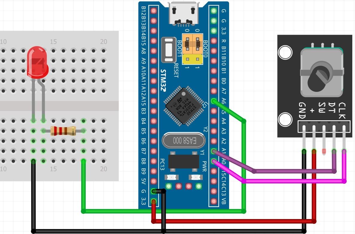
Connect the LED’s anode pin to PA6 through a 220 ohm resistor. The cathode pin will be grounded.
Demonstration
- Now connect your ST-LINK V2 with your computer via the USB port. Both the devices will power ON.
- Next press the RUN button in the IDE. The ‘Edit configuration’ window will open up. Click ‘OK’.
- After a few moments, the code will be successfully sent to the STM32 board. Otherwise, press the RESET button on your STM32 board.
- Now to bring the Blue pill back to normal mode make sure you bring the BOOT jumper back at its place.
Press the Reset button of STM32. Now rotate the knob of the rotary encoder and monitor how the brightness of the LED increases/decreases.
demo:
You may also like to read: