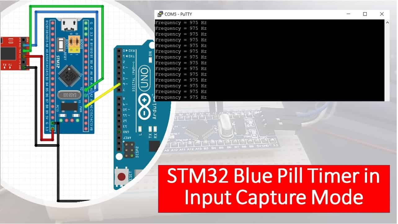
In this STM32 Blue Pill user guide, we will discuss how to configure timer module in input capture mode to measure the frequency of an input signal. We will program our STM32 Blue Pill in STM32 Cube IDE and build a frequency counter whereby one input capture channel will be enabled to capture an external signal on the rising edge.
Recommended Components
The following components are used in this project or are helpful for getting started with STM32 Blue Pill development.
| Component | How it’s used in this project | Buy on Amazon |
|---|---|---|
| STM32F103C8T6 Blue Pill Board | The STM32 board running the timer in input capture mode. | Check Price |
| ST-Link V2 Programmer | SWD programmer/debugger used to flash code onto the Blue Pill. | Check Price |
| USB-TTL / FTDI Converter | For viewing the measured frequency on a serial terminal over UART2. | Check Price |
| Breadboard & Jumper Wires | For wiring the signal source and programmer to the Blue Pill. | Check Price |
As an Amazon Associate we earn from qualifying purchases. Prices and availability are accurate as of the date/time indicated and are subject to change.
STM32 Blue Pill Timers
The Blue Pill STM32F103C8 comes with four timers known as TIM1, TIM2, TIM3, and TIM4. They act as a clock and are used to keep track of time based events. The timer module can work in different configurations such as timer mode, counter mode, PWM mode, output compare mode, etc. This guide focuses on configuring the timer module in input capture mode.
When configuring the STM32 Blue Pill timer module in input capture mode, an internal source clocks the timer module which is the input capture channel pin. When a particular event occurs on the input capture channel pin, its current value is captured and saved to the input capture register TIMx_CCRx. This sets the corresponding CCXIF flag and triggers the interrupt/DMA if it was configured. The capture/compare registers are responsible for securing the counter value after a transition detection occurs by the particular ICx sign.
The figure below shows the main circuit for capture channel 1.
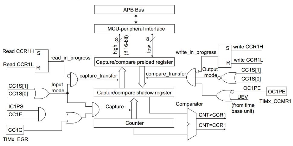
As you may see in the circuit above, the capture channel consists of a capture register with a shadow register, an input stage consisting of a digital filter, a multiplexer, and Prescaler for capturing, and an output stage consisting of output control and a comparator.
Timer configured in an input capture mode, is helpful in many applications where signal measurement and external event timing is required.
STM32 Blue Pill Timer in Input Capture Mode
Let’s create and build a project in STM32 CubeIDE to create a frequency counter by configuring the timer in input capture mode.
Open the CubeIDE and head over to a new project.
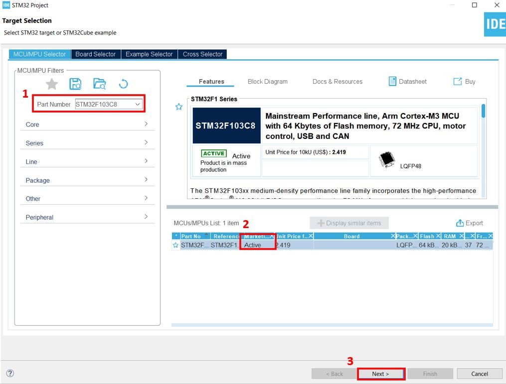
Then for the target selection, specify the STM32 Blue Pill board number. After that click on any column as shown in the picture below. Then click the ‘Next’ button.
Specify the name of your project then click ‘Finish’ to complete the setup of your project.
Setup Timer in Input Capture Mode
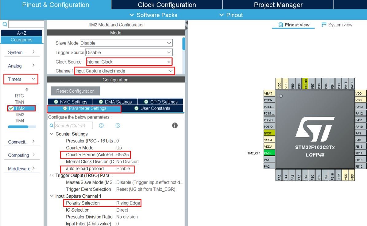
Now head over to Timers to configure the timer to work in input capture mode. We have selected Timer2. For the clock source, we have specified it as an ‘internal clock.’ Moreover, configure channel 1 as the input capture channel on the rising edge which is PA0.
Now go to the Parameter Settings and set the settings. As you may note the counter mode is set up as ‘Up.’ The counter period is set as 65535. The auto-reload is enabled and the rising edge is selected as the polarity.
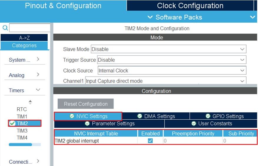
Then enable the TIM2 global interrupt. Head over to NVIC Settings inside Timers > TIM2 and enable it.
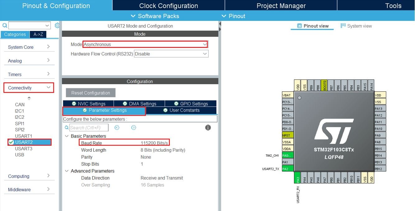
Now head over to Connectivity > USART2 and set the mode as ‘Asynchronous.’ You can also view the parameter settings of the UART including the baud rate, word length, parity, etc.
Now go to System Core > RCC then select ‘Crystal/Ceramic Resonator’ in from the High Speed Clock feature.
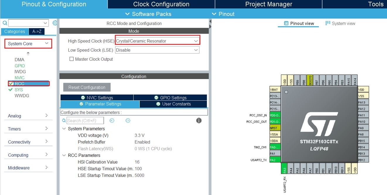
Now we have enabled the RCC external clock source.
Clock Configuration
Next, go to the Clock Configuration found at the top. This will open the following window. Here we will select the clock frequency.
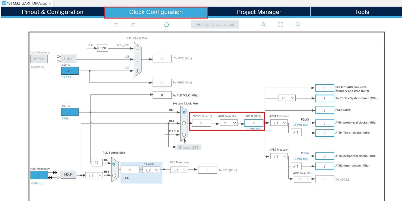
You can specify your system clock. We will set it as 72 MHz. These are the configurations we have set:

Now we will save our file. Press Ctrl + S. The following window will appear. Click ‘Yes.’ This will generate a template code for you.

Another window will appear that will ask if you want to open the perspective. Click ‘Yes.’

Frequency Measurement with STM32 Blue Pill
We will set up a code in which channel 1 will be set up as an input capture direct mode for all rising edges. The rising edge of any digital signal is an edge where the transition of the signal occurs from an active low level to an active high level. Furthermore, the time period is the time between two consecutive rising edges or falling edges.
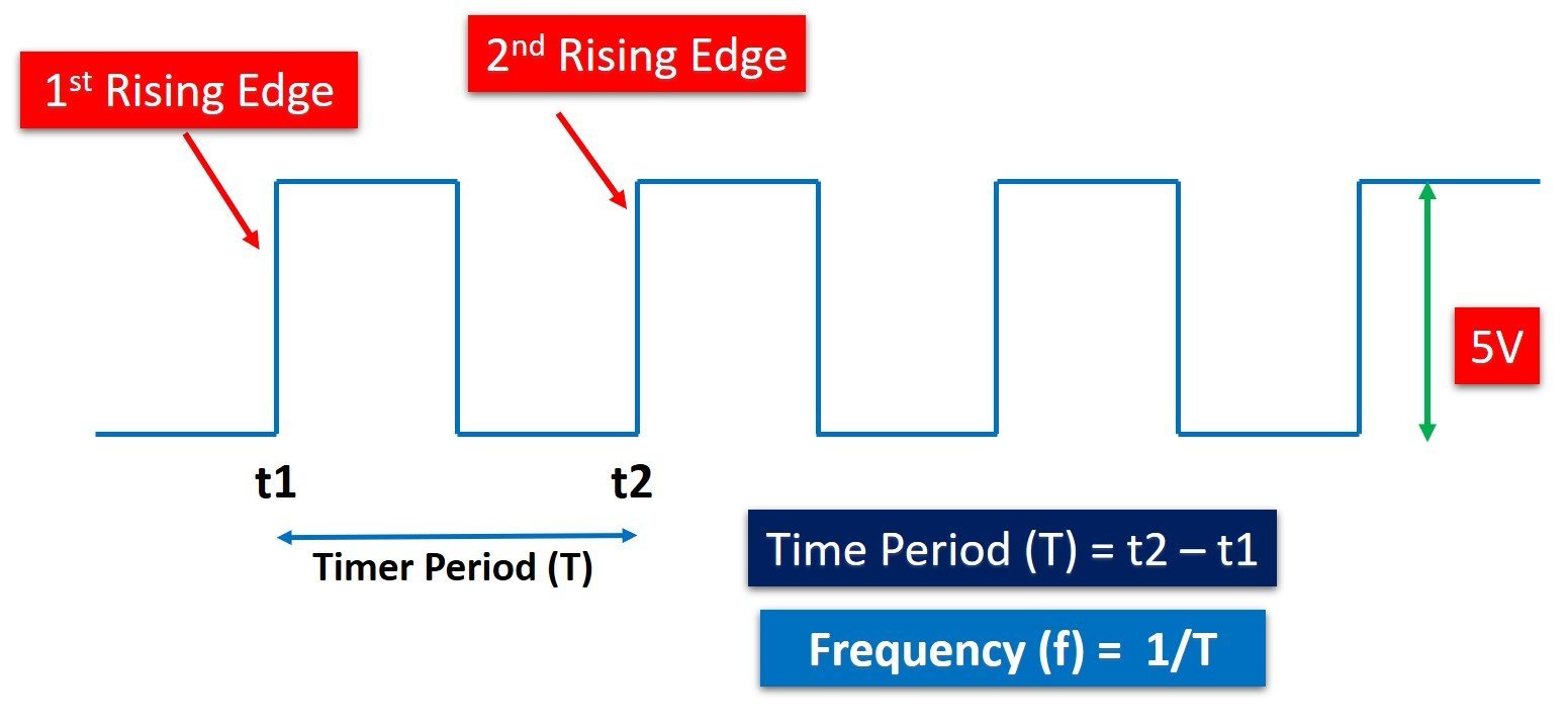
The external signal will be captured to measure frequency that we will use to build a frequency counter. To calculate the frequency values, we will first read from the CCR1 register and obtain the values on the first and second edge which will be T1 and T2 respectively. As the period of the input signal will be the subtracted value of T2 from T1, therefore frequency which is 1/period can be obtained from this value.
We will monitor the frequency readings in the serial terminal by connecting our STM32 Blue Pill with an FTDI programmer using UART2 pins that we set up. The frequency readings will be printed through UART2 in the form of a string.
Frequency Measurement Code
Now let us look at our main.c file that was generated.
Look for the MX_TIM2_Init() function.
static void MX_TIM2_Init(void)
{

  /* USER CODE BEGIN TIM2_Init 0 */

  /* USER CODE END TIM2_Init 0 */

  TIM_ClockConfigTypeDef sClockSourceConfig = {0};
  TIM_MasterConfigTypeDef sMasterConfig = {0};
  TIM_IC_InitTypeDef sConfigIC = {0};

  /* USER CODE BEGIN TIM2_Init 1 */

  /* USER CODE END TIM2_Init 1 */
  htim2.Instance = TIM2;
  htim2.Init.Prescaler = 0;
  htim2.Init.CounterMode = TIM_COUNTERMODE_UP;
  htim2.Init.Period = 65535;
  htim2.Init.ClockDivision = TIM_CLOCKDIVISION_DIV1;
  htim2.Init.AutoReloadPreload = TIM_AUTORELOAD_PRELOAD_ENABLE;
  if (HAL_TIM_Base_Init(&htim2) != HAL_OK)
  {
    Error_Handler();
  }
  sClockSourceConfig.ClockSource = TIM_CLOCKSOURCE_INTERNAL;
  if (HAL_TIM_ConfigClockSource(&htim2, &sClockSourceConfig) != HAL_OK)
  {
    Error_Handler();
  }
  if (HAL_TIM_IC_Init(&htim2) != HAL_OK)
  {
    Error_Handler();
  }
  sMasterConfig.MasterOutputTrigger = TIM_TRGO_RESET;
  sMasterConfig.MasterSlaveMode = TIM_MASTERSLAVEMODE_DISABLE;
  if (HAL_TIMEx_MasterConfigSynchronization(&htim2, &sMasterConfig) != HAL_OK)
  {
    Error_Handler();
  }
  sConfigIC.ICPolarity = TIM_INPUTCHANNELPOLARITY_RISING;
  sConfigIC.ICSelection = TIM_ICSELECTION_DIRECTTI;
  sConfigIC.ICPrescaler = TIM_ICPSC_DIV1;
  sConfigIC.ICFilter = 0;
  if (HAL_TIM_IC_ConfigChannel(&htim2, &sConfigIC, TIM_CHANNEL_1) != HAL_OK)
  {
    Error_Handler();
  }
  /* USER CODE BEGIN TIM2_Init 2 */

  /* USER CODE END TIM2_Init 2 */

}
This is the initialization function for Timer2. It configures the Timer2 on the set Prescaler, Preload, and Clock frequency values.
Modifying Code
Inside the main.c file, make sure the following code is part of your script by including the lines of code given below.
#include "main.h"

#define IDLE   0
#define DONE   1
#define F_CLK  72000000UL

volatile uint8_t state = IDLE;
volatile uint8_t message[35] = {'\0'};
volatile uint32_t T1 = 0;
volatile uint32_t T2 = 0;
volatile uint32_t ticks = 0;
volatile uint16_t TIM2_OVC = 0;
volatile uint32_t frequency = 0;

TIM_HandleTypeDef htim2;
UART_HandleTypeDef huart2;

void SystemClock_Config(void);
static void MX_GPIO_Init(void);
static void MX_TIM2_Init(void);
static void MX_USART2_UART_Init(void);


int main(void)
{
  HAL_Init();
  SystemClock_Config();

  MX_GPIO_Init();
  MX_TIM2_Init();
  MX_USART2_UART_Init();

  HAL_TIM_Base_Start_IT(&htim2);
  HAL_TIM_IC_Start_IT(&htim2, TIM_CHANNEL_1);

  while (1)
  {

  }

}

void HAL_TIM_IC_CaptureCallback(TIM_HandleTypeDef* htim)
{
    if(state == IDLE)
    {
        T1 = TIM2->CCR1;
        TIM2_OVC = 0;
        state = DONE;
    }
    else if(state == DONE)
    {
        T2 = TIM2->CCR1;
        ticks = (T2 + (TIM2_OVC * 65536)) - T1;
        frequency = (uint32_t)(F_CLK/ticks);
        if(frequency != 0)
        {
          sprintf(message, "Frequency = %lu Hz\n\r", frequency);
          HAL_UART_Transmit(&huart2, message, sizeof(message), 100);
        }
        state = IDLE;
    }
}

void HAL_TIM_PeriodElapsedCallback(TIM_HandleTypeDef* htim)
{
    TIM2_OVC++;
}
Enable and Start Timer in Input Capture Mode
We will first enable the timer in the following lines. Firstly, call MX_TIM2_Init() function to initialize Timer2 on the set Prescaler, Preload and Clock frequency values. Then call HAL_TIM_Base_Start_IT() to start the TIM Base generation in interrupt mode. It takes in a single parameter which is the pointer to the TIM_HandleTypeDef structure that holds the configuration parameters for the timer module. It is ‘&htim2’ in our case.
To start the timer input capture measurement in interrupt mode, we will call the function HAL_TIM_IC_Start_IT(). This function takes in two parameters. The first parameter is the pointer to the TIM_HandleTypeDef structure. The second parameter is the channel which is to be enabled. It can take any values from the ones listed below:
- TIM_CHANNEL_1: timer channel 1 is enabled
- TIM_CHANNEL_2: timer channel 2 is enabled
- TIM_CHANNEL_3: timer channel 3 is enabled
- TIM_CHANNEL_4: timer channel 4 is enabled
In our case, it is channel 1 that is selected.
TIM_HandleTypeDef htim2;
MX_TIM2_Init();

HAL_TIM_Base_Start_IT(&htim2);
HAL_TIM_IC_Start_IT(&htim2, TIM_CHANNEL_1);
Frequency Measurement
Inside the HAL_TIM_IC_CaptureCallback() function we check for two states: IDLE and DONE. If the state is IDLE, then capture the value of Timer2 to the CCR1 register for the first rising edge and save it in the variable ‘T1’ which initially held the value 0. At this point, an interrupt is triggered in which case the captured value of timer2 gets saved in T1 and the state changes to ‘DONE.’
When the state is DONE, then another rising edge occurs on the input capture channel 1 pin, the timer2 captured value to the CCR1 register is saved in the variable ‘T2’ which initially held the value 0. The frequency is calculated by dividing 1 by (T2-T1) which is the time period.
However, we took into account the timer2 overflow count as well. This is because there may be a situation where the timer2 overflows before the second rising edge occurs.The ‘TIM2_OVC’ variable holds the number of overflows that occurred after the first rising edge. This value multiplied by 65536 ticks is added to T2 before it gets subtracted from T1 to find the number of ticks. The frequency is then calculated by dividing the clock frequency by the number of ticks. This calculated frequency reading is transmitted to the system serial port through UART2. The state is again set to IDLE at this point.
void HAL_TIM_IC_CaptureCallback(TIM_HandleTypeDef* htim)
{
    if(state == IDLE)
    {
        T1 = TIM2->CCR1;
        TIM2_OVC = 0;
        state = DONE;
    }
    else if(state == DONE)
    {
        T2 = TIM2->CCR1;
        ticks = (T2 + (TIM2_OVC * 65536)) - T1;
        frequency = (uint32_t)(F_CLK/ticks);
        if(frequency != 0)
        {
          sprintf(message, "Frequency = %lu Hz\n\r", frequency);
          HAL_UART_Transmit(&huart2, message, sizeof(message), 100);
        }
        state = IDLE;
    }
}

void HAL_TIM_PeriodElapsedCallback(TIM_HandleTypeDef* htim)
{
    TIM2_OVC++;
}
main.c file
This is how a complete main.c file will be after modification.
#include "main.h"

#define IDLE   0
#define DONE   1
#define F_CLK  72000000UL
volatile uint8_t state = IDLE;
volatile uint8_t message[35] = {'\0'};
volatile uint32_t T1 = 0;
volatile uint32_t T2 = 0;
volatile uint32_t ticks = 0;
volatile uint16_t TIM2_OVC = 0;
volatile uint32_t frequency = 0;

TIM_HandleTypeDef htim2;
UART_HandleTypeDef huart2;

void SystemClock_Config(void);
static void MX_GPIO_Init(void);
static void MX_TIM2_Init(void);
static void MX_USART2_UART_Init(void);


int main(void)
{
  HAL_Init();
  SystemClock_Config();

  MX_GPIO_Init();
  MX_TIM2_Init();
  MX_USART2_UART_Init();

  HAL_TIM_Base_Start_IT(&htim2);
  HAL_TIM_IC_Start_IT(&htim2, TIM_CHANNEL_1);

  while (1)
  {

  }

}

void HAL_TIM_IC_CaptureCallback(TIM_HandleTypeDef* htim)
{
    if(state == IDLE)
    {
        T1 = TIM2->CCR1;
        TIM2_OVC = 0;
        state = DONE;
    }
    else if(state == DONE)
    {
        T2 = TIM2->CCR1;
        ticks = (T2 + (TIM2_OVC * 65536)) - T1;
        frequency = (uint32_t)(F_CLK/ticks);
        if(frequency != 0)
        {
          sprintf(message, "Frequency = %lu Hz\n\r", frequency);
          HAL_UART_Transmit(&huart2, message, sizeof(message), 100);
        }
        state = IDLE;
    }
}

void HAL_TIM_PeriodElapsedCallback(TIM_HandleTypeDef* htim)
{
    TIM2_OVC++;
}

/**
  * @brief System Clock Configuration
  * @retval None
  */
void SystemClock_Config(void)
{
  RCC_OscInitTypeDef RCC_OscInitStruct = {0};
  RCC_ClkInitTypeDef RCC_ClkInitStruct = {0};

  /** Initializes the RCC Oscillators according to the specified parameters
  * in the RCC_OscInitTypeDef structure.
  */
  RCC_OscInitStruct.OscillatorType = RCC_OSCILLATORTYPE_HSE;
  RCC_OscInitStruct.HSEState = RCC_HSE_ON;
  RCC_OscInitStruct.HSEPredivValue = RCC_HSE_PREDIV_DIV1;
  RCC_OscInitStruct.HSIState = RCC_HSI_ON;
  RCC_OscInitStruct.PLL.PLLState = RCC_PLL_ON;
  RCC_OscInitStruct.PLL.PLLSource = RCC_PLLSOURCE_HSE;
  RCC_OscInitStruct.PLL.PLLMUL = RCC_PLL_MUL9;
  if (HAL_RCC_OscConfig(&RCC_OscInitStruct) != HAL_OK)
  {
    Error_Handler();
  }
  /** Initializes the CPU, AHB and APB buses clocks
  */
  RCC_ClkInitStruct.ClockType = RCC_CLOCKTYPE_HCLK|RCC_CLOCKTYPE_SYSCLK
                              |RCC_CLOCKTYPE_PCLK1|RCC_CLOCKTYPE_PCLK2;
  RCC_ClkInitStruct.SYSCLKSource = RCC_SYSCLKSOURCE_PLLCLK;
  RCC_ClkInitStruct.AHBCLKDivider = RCC_SYSCLK_DIV1;
  RCC_ClkInitStruct.APB1CLKDivider = RCC_HCLK_DIV2;
  RCC_ClkInitStruct.APB2CLKDivider = RCC_HCLK_DIV1;

  if (HAL_RCC_ClockConfig(&RCC_ClkInitStruct, FLASH_LATENCY_2) != HAL_OK)
  {
    Error_Handler();
  }
}

/**
  * @brief TIM2 Initialization Function
  * @param None
  * @retval None
  */
static void MX_TIM2_Init(void)
{

  /* USER CODE BEGIN TIM2_Init 0 */

  /* USER CODE END TIM2_Init 0 */

  TIM_ClockConfigTypeDef sClockSourceConfig = {0};
  TIM_MasterConfigTypeDef sMasterConfig = {0};
  TIM_IC_InitTypeDef sConfigIC = {0};

  /* USER CODE BEGIN TIM2_Init 1 */

  /* USER CODE END TIM2_Init 1 */
  htim2.Instance = TIM2;
  htim2.Init.Prescaler = 0;
  htim2.Init.CounterMode = TIM_COUNTERMODE_UP;
  htim2.Init.Period = 65535;
  htim2.Init.ClockDivision = TIM_CLOCKDIVISION_DIV1;
  htim2.Init.AutoReloadPreload = TIM_AUTORELOAD_PRELOAD_ENABLE;
  if (HAL_TIM_Base_Init(&htim2) != HAL_OK)
  {
    Error_Handler();
  }
  sClockSourceConfig.ClockSource = TIM_CLOCKSOURCE_INTERNAL;
  if (HAL_TIM_ConfigClockSource(&htim2, &sClockSourceConfig) != HAL_OK)
  {
    Error_Handler();
  }
  if (HAL_TIM_IC_Init(&htim2) != HAL_OK)
  {
    Error_Handler();
  }
  sMasterConfig.MasterOutputTrigger = TIM_TRGO_RESET;
  sMasterConfig.MasterSlaveMode = TIM_MASTERSLAVEMODE_DISABLE;
  if (HAL_TIMEx_MasterConfigSynchronization(&htim2, &sMasterConfig) != HAL_OK)
  {
    Error_Handler();
  }
  sConfigIC.ICPolarity = TIM_INPUTCHANNELPOLARITY_RISING;
  sConfigIC.ICSelection = TIM_ICSELECTION_DIRECTTI;
  sConfigIC.ICPrescaler = TIM_ICPSC_DIV1;
  sConfigIC.ICFilter = 0;
  if (HAL_TIM_IC_ConfigChannel(&htim2, &sConfigIC, TIM_CHANNEL_1) != HAL_OK)
  {
    Error_Handler();
  }
  /* USER CODE BEGIN TIM2_Init 2 */

  /* USER CODE END TIM2_Init 2 */

}

/**
  * @brief USART2 Initialization Function
  * @param None
  * @retval None
  */
static void MX_USART2_UART_Init(void)
{

  /* USER CODE BEGIN USART2_Init 0 */

  /* USER CODE END USART2_Init 0 */

  /* USER CODE BEGIN USART2_Init 1 */

  /* USER CODE END USART2_Init 1 */
  huart2.Instance = USART2;
  huart2.Init.BaudRate = 115200;
  huart2.Init.WordLength = UART_WORDLENGTH_8B;
  huart2.Init.StopBits = UART_STOPBITS_1;
  huart2.Init.Parity = UART_PARITY_NONE;
  huart2.Init.Mode = UART_MODE_TX_RX;
  huart2.Init.HwFlowCtl = UART_HWCONTROL_NONE;
  huart2.Init.OverSampling = UART_OVERSAMPLING_16;
  if (HAL_UART_Init(&huart2) != HAL_OK)
  {
    Error_Handler();
  }
  /* USER CODE BEGIN USART2_Init 2 */

  /* USER CODE END USART2_Init 2 */

}

/**
  * @brief GPIO Initialization Function
  * @param None
  * @retval None
  */
static void MX_GPIO_Init(void)
{

  /* GPIO Ports Clock Enable */
  __HAL_RCC_GPIOD_CLK_ENABLE();
  __HAL_RCC_GPIOA_CLK_ENABLE();

}

/* USER CODE BEGIN 4 */

/* USER CODE END 4 */

/**
  * @brief  This function is executed in case of error occurrence.
  * @retval None
  */
void Error_Handler(void)
{
  /* USER CODE BEGIN Error_Handler_Debug */
  /* User can add his own implementation to report the HAL error return state */
  __disable_irq();
  while (1)
  {
  }
  /* USER CODE END Error_Handler_Debug */
}

#ifdef  USE_FULL_ASSERT
/**
  * @brief  Reports the name of the source file and the source line number
  *         where the assert_param error has occurred.
  * @param  file: pointer to the source file name
  * @param  line: assert_param error line source number
  * @retval None
  */
void assert_failed(uint8_t *file, uint32_t line)
{
  /* USER CODE BEGIN 6 */
  /* User can add his own implementation to report the file name and line number,
     ex: printf("Wrong parameters value: file %s on line %d\r\n", file, line) */
  /* USER CODE END 6 */
}
#endif /* USE_FULL_ASSERT */
Save the main.c file after modifying it. Now we are ready to build our project.
Building the Project
To build our project press Ctrl + B or go to Project > Build All.
Your project will start building. After a few moments, your project will be successfully built if there are no errors.
Connecting ST-Link Programmer with STM32
Now as we have successfully built our project let us move ahead and upload the code to our STM32 board. To do that, first we will have to connect our Blue Pill STM32 with a ST-Link programmer. We will be using ST-Link V2.

This will provide an interface between our computer and our STM32 board. It consists of 10 pins. We will be using pin2 SWDIO, pin6 SWCLK, pin4 GND, and pin8 3.3V to connect with our STM32 board. The SWDIO is the data input/output pin and the SWCLK is the clock pin. Follow the pin configuration given on ST-LINK V2 to identify each pin.
Follow the table below to connect both devices correctly.
| STM32 | ST-LINK V2 |
| VCC 3.3V pin | pin8 3.3V |
| SWDIO pin | pin2 SWDIO |
| SWCLK pin | pin6 SWCLK |
| GND pin | pin4 GND |

Additionally move the BOOT jumper to the right to enable the microcontroller to go into programming mode.

Hardware Setup for Frequency Measurement STM32 Blue Pill Timer in Input Capture Mode.
To demonstrate the working of the above given frequency measurement code, we will connect a 980Hz frequency signal to PA0 pin of STM32. We use Arduino Uno to generate 980Hz frequency digital signal through the PWM pin 6 of Arduino. The default frequency of Arduino PWM signal for pin 5 and pin 6 is 980 Hz.
For this project we will require the following components:
- STM32 Blue Pill
- Arduino Uno
- FTDI programmer/ USB to TTL converter
- Connecting Wires
- Breadboard
Connect the components as shown in the schematic diagram below:
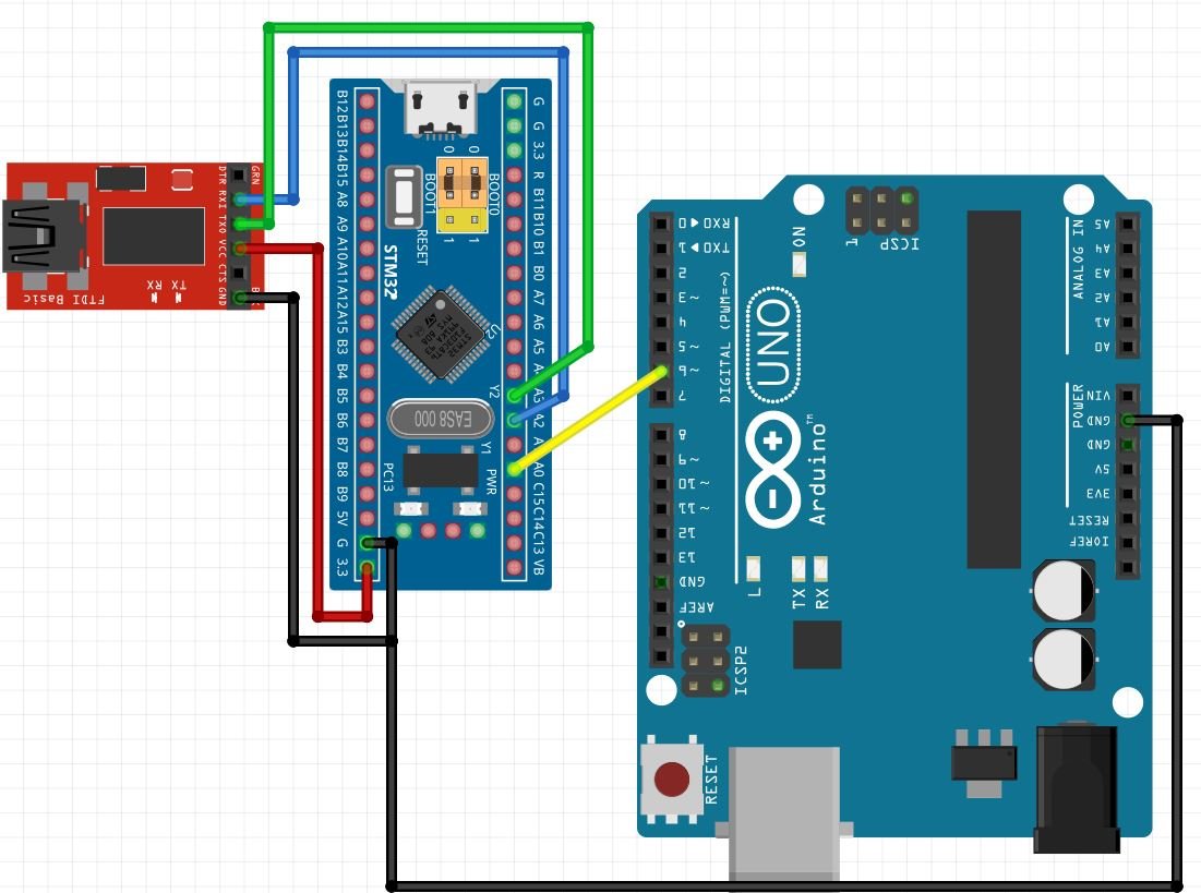
Connect Arduino PWM pin 6 with input capture pin PA0 of STM32 Blue Pin. Moreover, make sure both the microcontrollers have their ground in common.
For this guide, we are using UART2 module pins. VCC of the programmer is connected with 3.3V from the Blue pill and both the GND of the devices are connected together. PA2 is the TX2 pin of STM32 and PA3 is the RX2 pin of STM32. Connect the RX pin of STM32 with TX pin of FTDI and TX pin of STM32 with RX pin of FTDI converter.
Arduino Uno Program
After setting up the hardware, open Arduino IDE to program Arduino Uno with the following code:
int Pin = 6;      //PWM pin 6

void setup() {
  pinMode(Pin, OUTPUT);  // sets the pin as output
  analogWrite(Pin, 127); // analogRead values go from 0 to 1023, analogWrite values from 0 to 255
}

void loop() {
}
Demonstration
- Now connect your ST-LINK V2 with your computer via the USB port. Both STM32 Blue Pill and the ST-LINK V2 will power ON.
- Next press the RUN button in the IDE. The ‘Edit configuration’ window will open up. Click ‘OK’.
- After a few moments, the code will be successfully sent to the STM32 board. Otherwise, press the RESET button on your STM32 board.
- Now to bring the Blue pill back to normal mode make sure you bring the BOOT jumper back at its place.
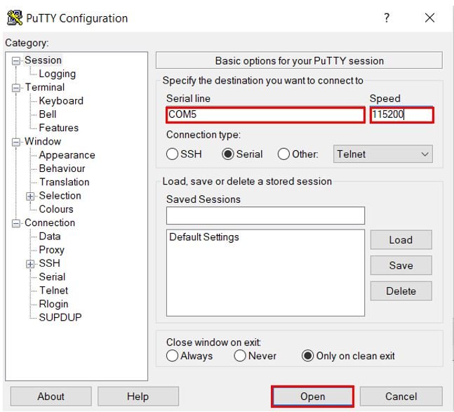
- Now connect the USB to TTL serial converter with the STM32 board as mentioned previously. Open Device Manager and head over to Ports to check the COM port through which the USB-TTL converter is connected. It is COM5 in our case.

- Open a terminal on your system for example Putty. Set the correct speed and COM port and then press Open to establish a connection.
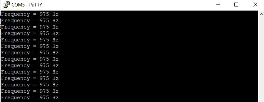
Press the Reset button of STM32. The terminal starts displaying the frequency readings. We are providing a 980Hz frequency signal and measuring 975Hz frequency value.
You may also like to read:
Hello,
I wanted to use this code on my STM32F103C8T6, without connecting the display to the screen with the UART, but simply by turning on the bluepill LED (PC13). So I removed the code steps from the UART configuration and just configured the LED instead. However I can’t get the program to work.
Do I need to call the HAL_TIM_IC_CaptureCallback function at some point or does it happen automatically?
Thanks for your help.
Hi
I have this code dowloaded from internet and its working fine.
Is there a way to calibrate the counte with this code?
I know that i can change this value >>TIMER1_BASE->ARR = 36000;
But still not exactly.
>>>>>>>
#include //https://github.com/wayoda/LedControl/archive/master.zip
LedControl lc = LedControl(PB1, PB10, PB11, 1); // DIN(PB1), CLK(PB10), CS(PB11)
volatile int mon_flag;
unsigned long freq;
byte fq[8], pd, x;
void setup() {
Serial.begin(9600);
lc.shutdown(0, false);
lc.setIntensity(0, 6); // ljusstyrka 0-15
lc.clearDisplay(0);
pinMode(PA15, INPUT_PULLDOWN); // ingång för frekvensmätare
RCC_BASE->APB1ENR |= (1 << 2) | (1 << 1) | (1 <APB2ENR |= (1 << 3) | (1 << 11) | (1 << 2) | (1 << 0) | (1 <MAPR = (1 << 8) | (1 <= 10000000) {
x = 8;
}
if (freq < 10000000) {
lc.setRow(0, 7, 0);
x = 7;
}
if (freq < 1000000) {
lc.setRow(0, 6, 0);
x = 6;
}
if (freq < 100000) {
lc.setRow(0, 5, 0);
x = 5;
}
if (freq < 10000) {
lc.setRow(0, 4, 0);
x = 4;
}
if (freq < 1000) {
lc.setRow(0, 3, 0);
x = 3;
}
if (freq < 100) {
lc.setRow(0, 2, 0);
x = 2;
}
if (freq < 10) {
lc.setRow(0, 1, 0);
x = 1;
}
for (int i = 0; i CR1 = 0; //stopp timer
TIMER2_BASE->CCER = 0; TIMER2_BASE->PSC = 0; TIMER2_BASE->CNT = 0;
TIMER2_BASE->CCR1 = 0; TIMER2_BASE->CCR2 = 0; TIMER2_BASE->CCR3 = 0;
TIMER2_BASE->CCR4 = 0; TIMER2_BASE->PSC = 0; TIMER2_BASE->SR = 0;
TIMER2_BASE->CCMR2 = 0;
TIMER2_BASE->CR2 = 1 <SMCR = (1 <ARR = 65535; //count to maximum
TIMER2_BASE->EGR = 1; //läs om register.
TIMER2_BASE->CR1 |= (1 <CR1 = 1 <CCER = 0; TIMER3_BASE->PSC = 0; TIMER3_BASE->CNT = 0;
TIMER3_BASE->CCR1 = 0; TIMER3_BASE->CCR2 = 0; TIMER3_BASE->CCR3 = 0;
TIMER3_BASE->CCR4 = 0; TIMER3_BASE->PSC = 0; TIMER3_BASE->SR = 0; TIMER3_BASE->CR2 = 0;
TIMER3_BASE->CCMR1 = 0;
TIMER3_BASE->SMCR = (1 << 2) | (1 << 1) | (1 << 0) | (1 <ARR = 65535; //count up
TIMER3_BASE->EGR = 1; //läs om register.
TIMER3_BASE->CR1 |= (1 <CR1 = (1 << 3) | (1 <CNT = 0;
TIMER1_BASE->CR2 = (1 <CCER = 0; // inaktivera timerutgångar till fysiska ben
TIMER1_BASE->PSC = F_CPU / 36000 – 1 ; // 1999; // 72000000/2000= 36000 kHz timerklocka
TIMER1_BASE->ARR = 36000; //räkna upp till 36000 (1 sekund)
TIMER1_BASE->EGR = 1; //läs om register.
TIMER1_BASE->CR1 |= (1 <CR1 & 1) {
asm volatile(“nop”);
if (mon_flag) {
return;
}
}
freq = TIMER3_BASE->CNT <CNT ;
}
Are you sure that you want to read from CCR1? Don’t you want CNT?