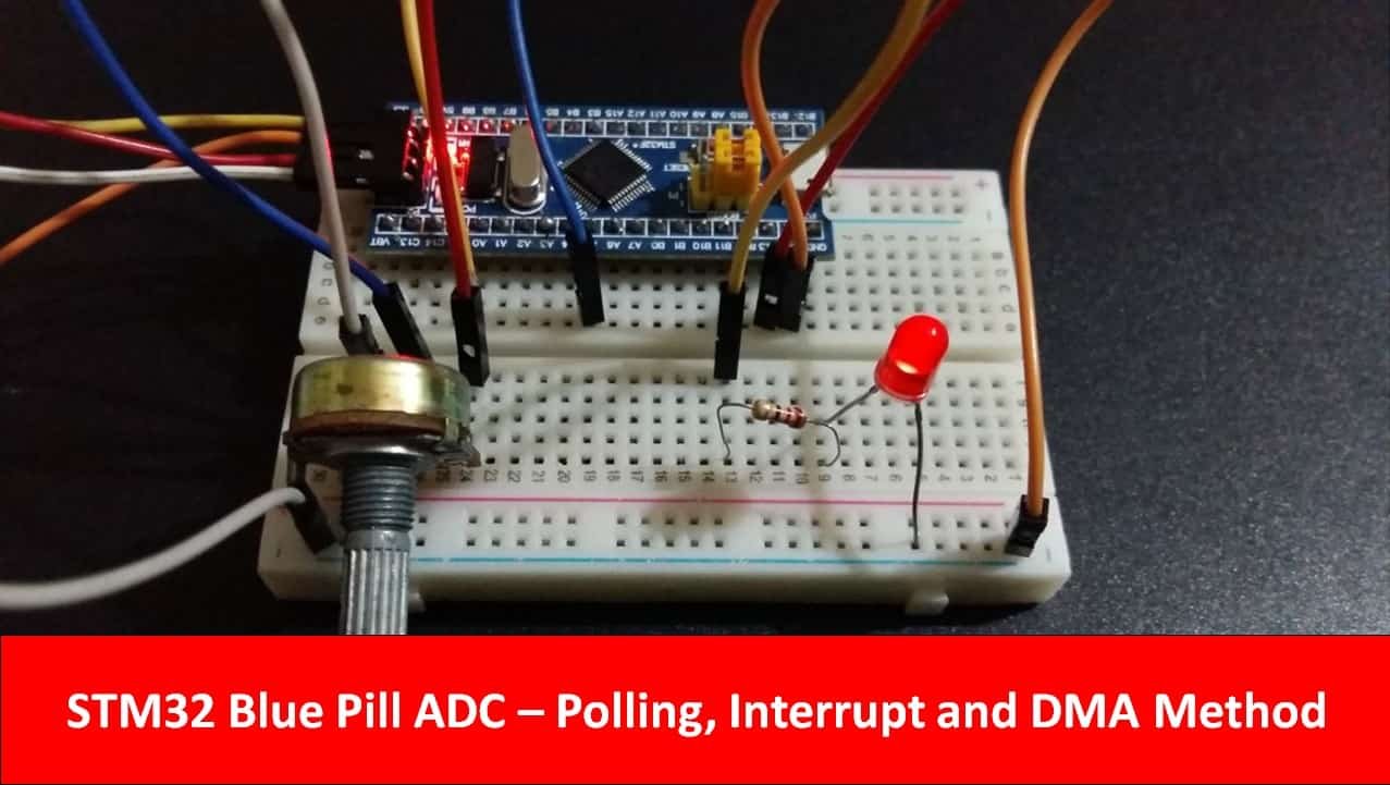
In this STM32 Blue Pill tutorial, we will learn to use ADC and read analog input voltage using STM32CubeIDE and HAL libraries. We will discuss three methods to read ADC including polling, interrupt, and DMA method. This will be demonstrated with the help of an LED dimmer example where we will connect the potentiometer as an analog input with one of the ADC pins of STM32 and measured digital values will be mapped to the PWM duty cycle which will control an LED brightness.
Recommended Components
The following components are used in this project or are helpful for getting started with STM32 Blue Pill development.
| Component | How it’s used in this project | Buy on Amazon |
|---|---|---|
| STM32F103C8T6 Blue Pill Board | The STM32 board reading the analog input via ADC. | Check Price |
| ST-Link V2 Programmer | SWD programmer/debugger used to flash code onto the Blue Pill. | Check Price |
| 10kΩ Potentiometer | The analog input that varies the ADC reading. | Check Price |
| 5mm LED | Its brightness is controlled by the mapped ADC value. | Check Price |
| Resistor Kit (incl. 220Ω) | A 220Ω current-limiting resistor for the LED. | Check Price |
| Breadboard & Jumper Wires | For wiring the potentiometer and LED to the Blue Pill. | Check Price |
As an Amazon Associate we earn from qualifying purchases. Prices and availability are accurate as of the date/time indicated and are subject to change.
STM32 Blue Pill ADC Polling Method
As mentioned before, there are three ways of accessing ADC values. We will look at all three of them separately. Let us start with the first method which is known as polling. In this scenario, the ADC module is configured in blocking mode. When the ADC conversion initiates, the CPU stops until the ADC conversion is finished. After the ADC conversion completes, the CPU starts again and continues with the execution of the main code.
We will use STM32Cube IDE to program our STM32 board. Open the IDE and head over to a new project.
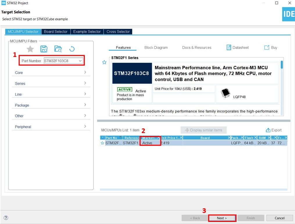
Then for the target selection, specify the STM32 Blue Pill board number. After that click on any column as shown in the picture below. Then click the ‘Next’ button.
Specify the name of your project then click ‘Finish’ to complete the setup of your project.
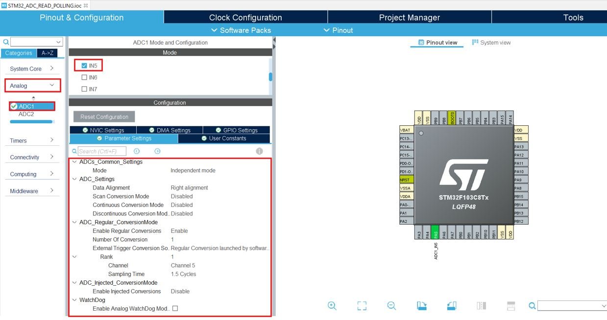
Firstly, we will set up an Analog Input Pin in single Conversion Mode. This will be connected with the potentiometer. Head over to Analog and select ADC1. We have selected PA5 (channel 5) as the input pin and you can also view the parameter settings of the analog channel that we selected.
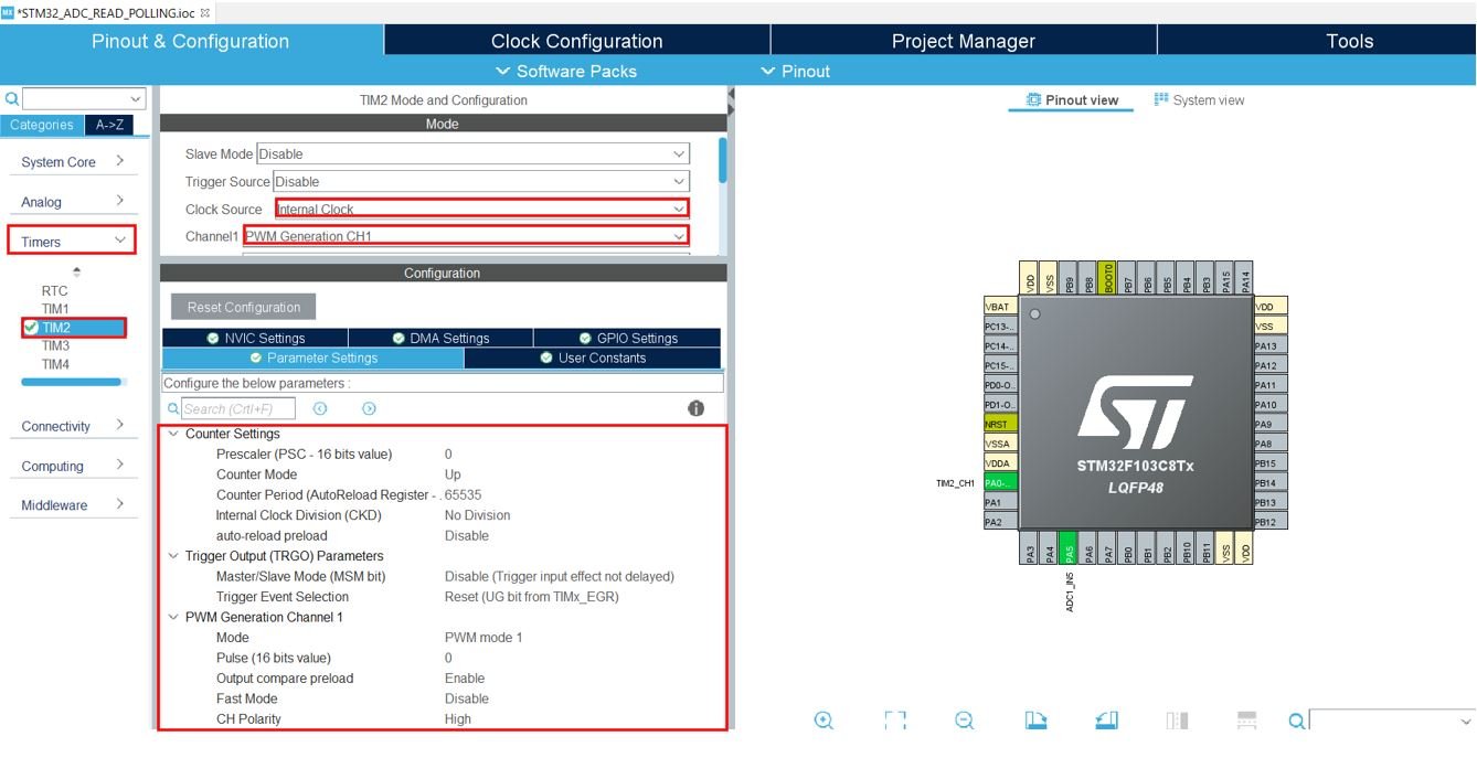
Next head over to Timers and select TIM2. The mode for Timer2 is set next where we configure the clock source as the internal clock and Channel 1 as PWM Generation CH1. This way Timer2 will work in PWM mode where PA0 (Timer2 Channel 1) will be set as an output.
Now go to System Core > RCC then select ‘Crystal/Ceramic Resonator’ from the High-Speed Clock feature.
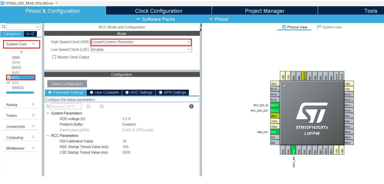
Now we have enabled the RCC external clock source.
Clock Configuration
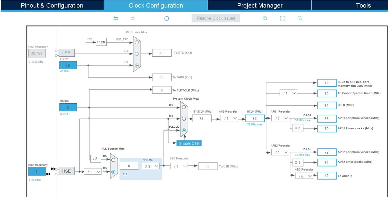
Next go to the Clock Configuration found at the top. This will open the following window. Here we will select the clock frequency.
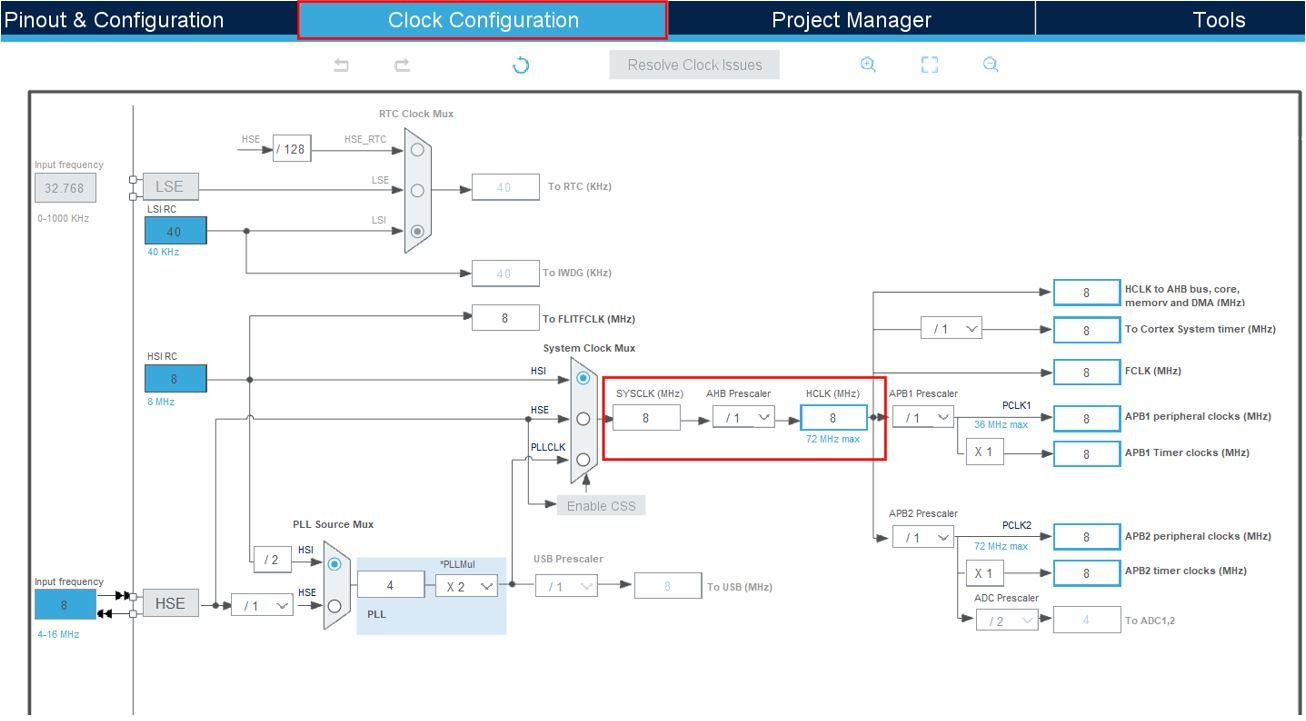
You can specify your system clock. We will set it as 72MHz. These are the configurations we have set. The ADC peripherals are assigned a default clock of 12MHz.
Now we will save our file. Press Ctrl + S. The following window will appear. Click ‘Yes.’ This will generate a template code for you.

Another window will appear that will ask if you want to open the perspective. Click ‘Yes.’

ADC Read Polling Method with STM32 Blue Pill Code
Now let us look at our main.c file that was generated.
We will set up a code in which the ADC is initialized at Channel 5 where a potentiometer is connected and the timer2 is configured to work in PWM mode with Channel 1 as an output where an LED will be connected. The ADC values will be converted to equivalent duty cycle values that will alter the brightness of the LED. However, in this case the ADC module will work in polling (blocking mode).
Inside the main.c file, look for the int main() function. Copy the code given below in the main() function.
int main(void)
{
  uint16_t AD_RES = 0;
  HAL_Init();
  SystemClock_Config();
  MX_GPIO_Init();
  MX_ADC1_Init();
  MX_TIM2_Init();

  HAL_TIM_PWM_Start(&htim2, TIM_CHANNEL_1);
  HAL_ADCEx_Calibration_Start(&hadc1);

  while (1)
      {
          HAL_ADC_Start(&hadc1);
          HAL_ADC_PollForConversion(&hadc1, 1);
          AD_RES = HAL_ADC_GetValue(&hadc1);
          TIM2->CCR1 = (AD_RES<<4);
          HAL_Delay(1);
      }
}
Configure ADC in Polling Mode
The HAL_ADCEx_Calibration_Start() function is called to start an automatic calibration. This function takes in a parameter which is the pointer to a ADC_HandleTypeDef structure that contains the configuration information for the specified ADC. It is ‘&hadc1’ in our case.
HAL_ADCEx_Calibration_Start(&hadc1);Inside the while loop, we call HAL_ADC_Start() to enable the ADC and start the conversion of the regular channels. It takes in a single parameter ‘hadc’ which is the pointer to a ADC_HandleTypeDef structure that contains the configuration information for the specified ADC. It is ‘&hadc1’ in our case.
HAL_ADC_Start(&hadc1);Then we call HAL_ADC_PollForConversion() to poll for regular conversion. It takes in two parameters. The first parameter is the pointer to a ADC_HandleTypeDef structure that contains the configuration information for the specified ADC which is ‘&hadc1’ in our case. The second parameter is the timeout in milliseconds which we have specified as 1 millisecond.
HAL_ADC_PollForConversion(&hadc1, 1);After that the ADC conversion value from data register of regular channel is acquired by using HAL_ADC_GetValue() and mapped to the PWM duty cycle. The ADC conversion value is read and shifted to the timer CCR register which sets the PWM duty cycle percentage for the output LED pin.
 AD_RES = HAL_ADC_GetValue(&hadc1);
 TIM2->CCR1 = (AD_RES<<4);
Save the main.c file after modifying it. Now we are ready to build our project.
Building the Project
To build our project press Ctrl + B or go to Project > Build All.
Your project will start building. After a few moments, your project will be successfully built if there are no errors.
Connecting ST-Link Programmer with STM32
Now as we have successfully built our project let us move ahead and upload the code to our STM32 board. To do that, first we will have to connect our Blue Pill STM32 with a ST-Link programmer. We will be using ST-Link V2.

This will provide an interface between our computer and our STM32 board. It consists of 10 pins. We will be using pin2 SWDIO, pin6 SWCLK, pin4 GND, and pin8 3.3V to connect with our STM32 board. The SWDIO is the data input/output pin and the SWCLK is the clock pin. Follow the pin configuration given on the ST-LINK V2 to identify each pin.
Follow the table below to connect both devices correctly.
| STM32 | ST-LINK V2 |
| VCC 3.3V pin | pin8 3.3V |
| SWDIO pin | pin2 SWDIO |
| SWCLK pin | pin6 SWCLK |
| GND pin | pin4 GND |

Additionally move the BOOT jumper to the right to enable the microcontroller to go into programming mode.

Hardware Setup for ADC LED Dimmer
For this ADC Read LED Dimmer project we will require the following components:
- STM32 Blue Pill
- One 10k Potentiometer
- One 5mm LED
- One 220 ohm current limiting resistor
- Connecting Wires
- Breadboard
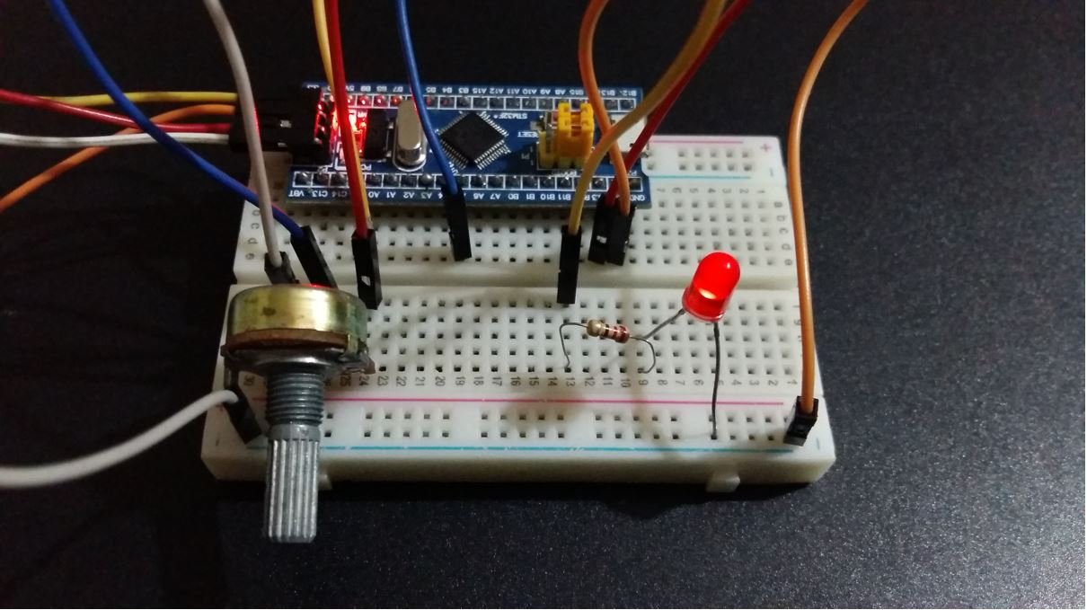
Connect the components as shown in the schematic diagram below:
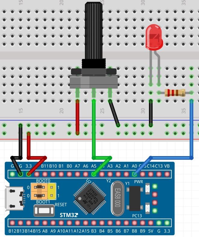
Connect one terminal of potentiometer with 3.3V to power it up, the center terminal with PA5, and the third terminal with common ground. Connect the LED’s anode pin to PA0 through a 220-ohm resistor. The cathode pin will be grounded.
Demonstration
- Now connect your ST-LINK V2 with your computer via the USB port. Both devices will power ON.
- Next press the RUN button in the IDE. The ‘Edit configuration’ window will open up. Click ‘OK’.
- After a few moments, the code will be successfully sent to the STM32 board. Otherwise, press the RESET button on your STM32 board.
- Now to bring the Blue pill back to normal mode hence make sure you bring the BOOT jumper back at its place.
Rotate the knob of the potentiometer and the LED’s brightness will change as the ADC values increase/decrease.
STM32 Blue Pill ADC Interrupt Method
In this section let us configure the ADC module using the interrupt method. In this scenario, the ADC module is configured in non-blocking mode where the ADC is triggered to start the ADC conversion. Unlike the polling method, the CPU does not stop but continues the execution of the main code. The completion of the ADC conversion marks the triggering of the interrupt. This enables the CPU to change situation to the ISR handler and save the ADC conversion values. Using interrupt method with high rate of conversions can however overload the CPU.
To work using the interrupt method, create a new project in STM32 Cube IDE and follow similar steps as before.
- Specify the target selection and then name of your project to complete the setup of your project.
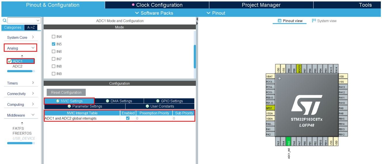
- Firstly, we will set up an Analog Input Pin in single Conversion Mode. This will be connected with the potentiometer. Head over to Analog and select ADC1. We have selected PA5 (channel 5) as the input pin. Head over to NVIC Settings under configuration and enable the ADC1 and ADC2 global interrupt.
The rest of the steps are same as we did previously.
- Select Timer2 to work in PWM Mode and Output on Channel 1.
- Now go to System Core > RCC then select ‘Crystal/Ceramic Resonator’ in from the High Speed Clock feature. Now we have enabled the RCC external clock source.
- Next go to the Clock Configuration found at the top. This will open the following window. Here we will select the clock frequency. You can specify your system clock. We will set it as 72MHz. These are the configurations we have set. The ADC peripherals are assigned a default clock of 12MHz.
Now we will save our file. Press Ctrl + S. The following window will appear. Click ‘Yes.’ This will generate a template code for you.
Another window will appear that will ask if you want to open the perspective. Click ‘Yes.’
ADC Read Interrupt Method with STM32 Blue Pill Code
Now let us look at our main.c file that was generated.
We will set up a code in which the ADC is initialized at Channel 5 where a potentiometer is connected and the timer2 is configured to work in PWM mode with Channel 1 as an output where an LED will be connected. The ADC values will be converted to equivalent duty cycle values that will alter the brightness of the LED. However, in this case the ADC module is configured in interrupt mode (non-blocking mode).
Inside the main.c file, look for the int main() function. Copy the code given below in the main() function.
uint16_t AD_RES = 0;

int main(void)
{
  HAL_Init();

  /* Configure the system clock */
  SystemClock_Config();

  /* Initialize all configured peripherals */
  MX_GPIO_Init();
  MX_ADC1_Init();
  MX_TIM2_Init();

  HAL_TIM_PWM_Start(&htim2, TIM_CHANNEL_1);
  HAL_ADCEx_Calibration_Start(&hadc1);

  while (1)
  {
      HAL_ADC_Start_IT(&hadc1);
      TIM2->CCR1 = (AD_RES<<4);
      HAL_Delay(1);
  }
}
Configure ADC in Interrupt Mode
The HAL_ADC_Start_IT() function is responsible for enabling the interrupt and starting ADC conversion of regular channels. It takes in a single parameter which is the pointer to the ADC_HandleTypeDef structure that contains the configuration parameters for the specified ADC. In our case it is ‘&hadc1.’
HAL_ADC_Start_IT(&hadc1);The HAL_ADC_ConvCpItCallback() function is the regular conversion complete callback in non blocking mode. It also takes in the same parameter which is the pointer to the ADC_HandleTypeDef structure. Inside this callback, the ADC value is read and updated using HAL_ADC_GetValue().
void HAL_ADC_ConvCpltCallback(ADC_HandleTypeDef* hadc)
{
    AD_RES = HAL_ADC_GetValue(&hadc1);
}
Save the main.c file after modifying it. Now build and flash the project and it will give same results as with the polling method.
STM32 Blue Pill ADC DMA Method
Lastly, we will show you how to configure the ADC module using the DMA method. In this scenario, the ADC module is configured in non-blocking mode where the DMA sends the ADC values from the peripheral to the memory directly. The CPU is not involved as was the case in polling and interrupt.
To configure ADC using the DMA unit, create a new project in STM32 Cube IDE and follow similar steps as before.
- Specify the target selection and then name of your project to complete the setup of your project.
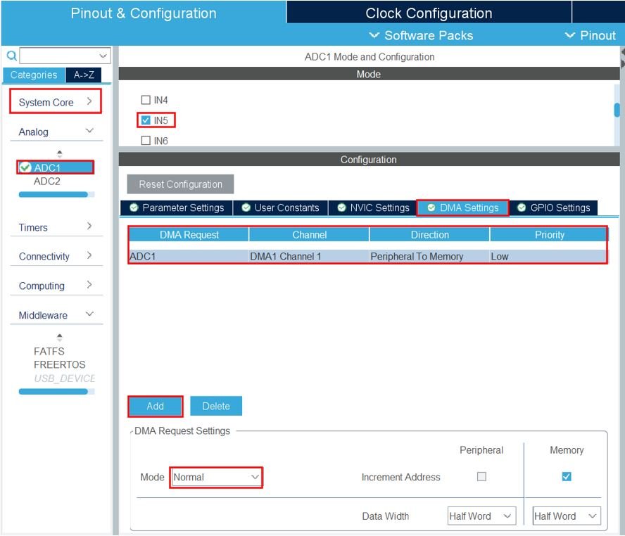
- Firstly, we will set up an Analog Input Pin in single Conversion Mode. This will be connected with the potentiometer. Head over to Analog and select ADC1. We have selected PA5 (channel 5) as the input pin. Head over to DMA Settings and add the DMA request for the particular peripheral by clicking the Add button. Select ADC1. You can view the details off the DMA request by clicking the DMA that was just added. We have set the mode as ‘Normal.’ You can even set it as ‘Circular’ in which case the DMA continuously updates the data.
The rest of the steps are same as we did previously in polling and interrupt modes.
- Select Timer2 to work in PWM Mode and Output on Channel 1.
- Now go to System Core > RCC then select ‘Crystal/Ceramic Resonator’ in from the High Speed Clock feature. Now we have enabled the RCC external clock source.
- Next go to the Clock Configuration found at the top. This will open the following window. Here we will select the clock frequency. You can specify your system clock. We will set it as 72MHz. These are the configurations we have set. The ADC peripherals are assigned a default clock of 12MHz.
Now we will save our file. Press Ctrl + S. The following window will appear. Click ‘Yes.’ This will generate a template code for you.
Another window will appear that will ask if you want to open the perspective. Click ‘Yes.’
ADC Read DMA Method with STM32 Blue Pill Code
Now let us look at our main.c file that was generated.
We will set up a code in which the ADC is initialized at Channel 5 where a potentiometer is connected and the timer2 is configured to work in PWM mode with Channel 1 as an output where an LED will be connected. The ADC values will be converted to equivalent duty cycle values that will alter the brightness of the LED. However, in this case the ADC module is configured in DMA mode (non-blocking mode).
Inside the main.c file, look for the int main() function. Copy the code given below in the main() function.
uint16_t AD_RES = 0;

int main(void)
{
    HAL_Init();
    SystemClock_Config();
    MX_GPIO_Init();
    MX_DMA_Init();
    MX_ADC1_Init();
    MX_TIM2_Init();
    HAL_TIM_PWM_Start(&htim2, TIM_CHANNEL_1);

    HAL_ADCEx_Calibration_Start(&hadc1);

    while (1)
    {
        HAL_ADC_Start_DMA(&hadc1, &AD_RES, 1);
        HAL_Delay(1);
    }
}
Configure ADC in DMA Mode
The HAL_ADC_Start_DMA() function is responsible for enabling the ADC DMA request after last transfer in Single-ADC mode and also enabling the ADC peripheral. It takes in three parameters. The first parameter is the pointer to the ADC_HandleTypeDef structure holding the configuration parameters for the specified ADC. The second parameter is the destination buffer address. The third parameter is the length of data that will be shifted from the ADC peripheral to memory.
HAL_ADC_Start_DMA(&hadc1, &AD_RES, 1);The HAL_ADC_ConvCpItCallback() function is the regular conversion complete callback in non-blocking mode. It takes in a single parameter which is the pointer to the ADC_HandleTypeDef structure. At this point, the ADC conversion and DMA transfer finishes, hence the destination buffer address gets updated. This ADC conversion value is mapped to the PWM duty cycle which determines the brightness of the LED.
void HAL_ADC_ConvCpltCallback(ADC_HandleTypeDef* hadc)
{

   TIM2->CCR1 = (AD_RES<<4);
}
Save the main.c file after modifying it. Now build and flash the project and it will give same results as with the polling and interrupt methods.
You may also like to read:
- STM32 Blue Pill UART Communication Tutorial with CubeIDE and HAL Libraries
- STM32 Blue Pill UART Interrupt with CubeIDE and HAL Libraries
- STM32 Blue Pill UART DMA with STM32Cube IDE and HAL Libraries
- STM32 Blue Pill Timer Interrupt with STM32Cube IDE and HAL Libraries
- Push Button with STM32 Blue Pill using STM32Cube IDE – Read Digital Input Pins
- STM32 Blue Pill External Interrupts with STM32Cube IDE and HAL Libraries
- STM32 Blue Pill GPIO Pins with STM32Cube IDE: LED Blinking Tutorial