In this tutorial, we will learn how to interface DS18B20 temperature sensor with STM32 Blue Pill and program it in STM32CubeIDE using HAL libraries. Firstly, we will briefly introduce you to DS18B20 sensor, then interface it with STM32 and program it for temperature measurement using STMCube IDE. For demonstration, we will connect an SSD1306 OLED with the STM32 Blue Pill to display the sensor data on the OLED.
Recommended Components
The following components are used in this project or are helpful for getting started with STM32 Blue Pill development.
| Component | How it’s used in this project | Buy on Amazon |
|---|---|---|
| STM32F103C8T6 Blue Pill Board | The STM32 board reading the sensor and driving the OLED. | Check Price |
| ST-Link V2 Programmer | SWD programmer/debugger used to flash code onto the Blue Pill. | Check Price |
| DS18B20 Temperature Sensor | The 1-Wire digital temperature sensor read in this project. | Check Price |
| Resistor Kit (incl. 4.7kΩ) | The 4.7kΩ pull-up resistor for the DS18B20 data line. | Check Price |
| 0.96" SSD1306 OLED Display | I2C OLED used to display the temperature readings. | Check Price |
| Breadboard & Jumper Wires | For wiring the sensor and OLED to the Blue Pill. | Check Price |
As an Amazon Associate we earn from qualifying purchases. Prices and availability are accurate as of the date/time indicated and are subject to change.
DS18B20 Introduction
DS18B20 is a temperature sensor that is single-wire programmable in nature. It is widely used to measure the temperature of chemical solutions and substances which are present in a hard environment. One of the advantages of using this sensor is that we only require a single pin of our microcontrollers to transfer data. Thus, it is extremely convenient to use this sensor with a microcontroller as we can measure multiple temperatures by using the least number of pins of our development board.
The table below shows some key characteristics of the ds18b120 sensor.
| Feature | Value |
|---|---|
| Operating Voltage | 3-5V |
| Temperature Range | -55°C to +125°C |
| Accuracy | ±0.5°C |
| Output Resolution | 9-12 bit |
Pinout Diagram
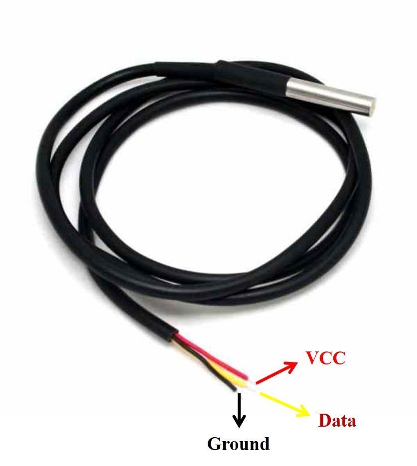
A waterproof version of this sensor is also available in the market. The following figures show the pinout of the DS18B20 sensors.
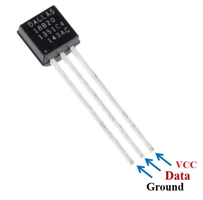
The following diagram shows the pinout of the normal DS18B20 temperature sensor.
The table below lists the pin configurations:
| Pin | Description |
|---|---|
| VCC | This is the pin that powers up the sensor. It is 3.3V or 5V for STM32 Blue Pill boards. |
| Data | This pin gives the temperature reading. |
| Ground | This pin is connected with the ground |
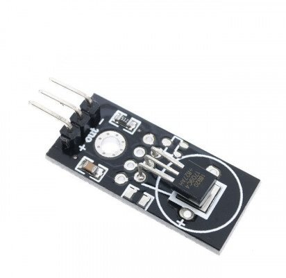
This temperature sensor also comes in a single package module which contains a sensor and a pull-up resistor. If you are using a module, you do not need to connect an external 4.7K ohm resistor. This is because the module already has an onboard pull-up resistor.
Interface DS18B20 sensor with STM32 Blue Pill and OLED
We will need the following components for this project.
- STM32 Blue Pill board
- DS18B20 Sensor
- 4.7k ohm resistor
- SSD1306 OLED
- Breadboard
- Connecting Wires
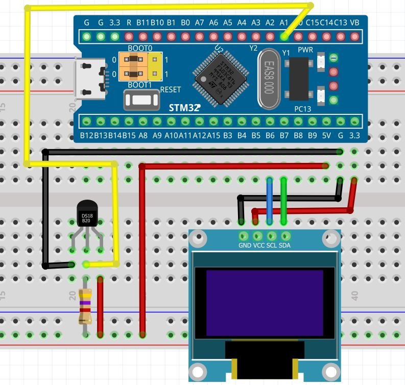
The connections between DS18B20 and Blue Pill can be seen below.
| DS18B20 Sensor Pin | STM32 Blue Pill Pin |
|---|---|
| GND | GND |
| Data | The data out pin will be connected with a GPIO output pin with a 4.7k ohm pull-up resistor. We will use PA1 to connect with the data pin. |
| VCC | 5V |
The connections between the OLED and Blue Pill can be seen below.
| STM32 Blue Pill | SSD1306 OLED Display |
|---|---|
| 3.3V | VCC |
| PB7 (I2C1_SDA) | SDA |
| PB6 (I2C1_SCL) | SCL |
| GND | GND |
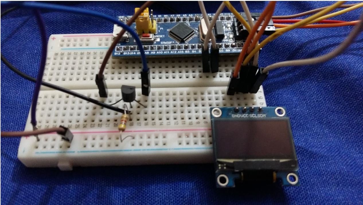
Connect the DS18B20 sensor and OLED with STM32 Blue Pill as shown in the schematic diagram below. We are using the same connections as specified in the tables above.
You can read this in-depth guide on OLED with STM32:
STM32 Blue Pill DS18B20 with OLED using STMCube IDE
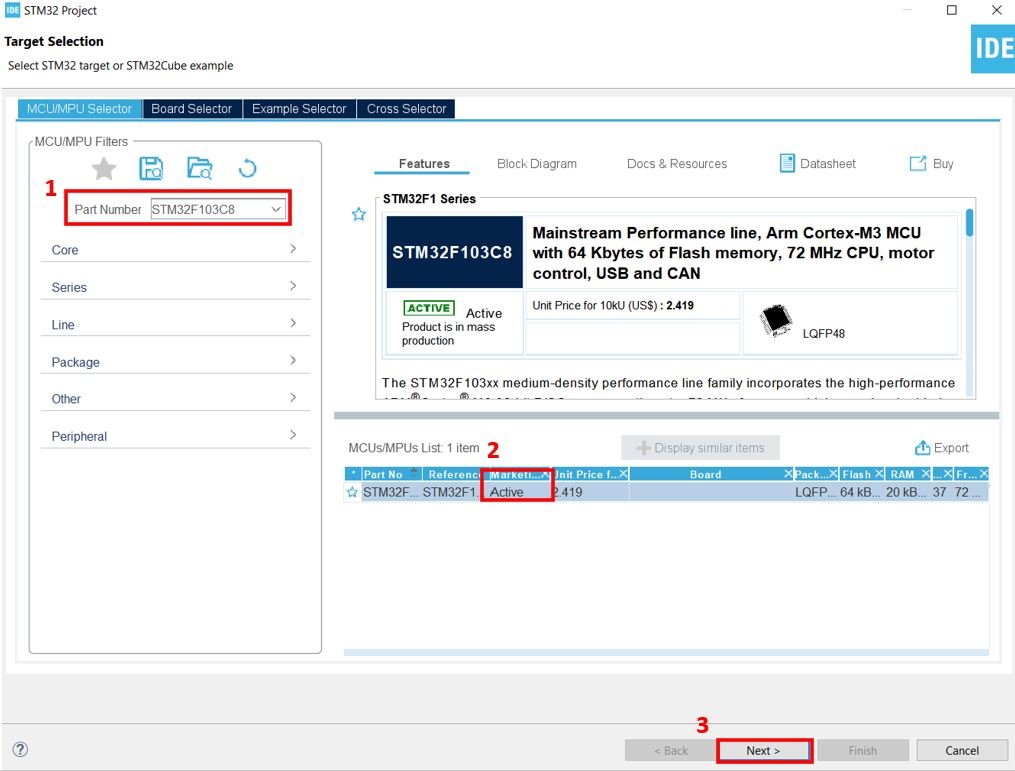
We will use STM32Cube IDE to program our STM32 board. Open the IDE and head over to a new project.
Then for the target selection, specify the STM32 Blue Pill board number. After that click on any column as shown in the picture below. Then click the ‘Next’ button.
Specify the name of your project then click ‘Finish’ to complete the setup of your project.
Go to System Core > RCC then select ‘Crystal/Ceramic Resonator’ in from the High Speed Clock feature.
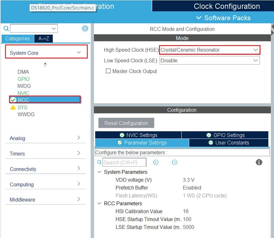
Now we have enabled the RCC external clock source.
Now head over to Timers > TIM1 and select the Clock Source as ‘Internal Clock.’ Then click the Parameter Settings and set the Prescaler as 63 and set the trigger event selection as Reset.

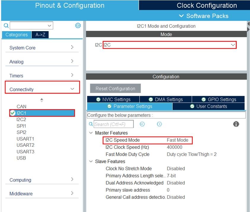
Head over to Connectivity > I2C1. Select the I2C mode as ‘I2C.’ Then go to ‘Parameter Settings’ and set the I2C speed mode as ‘Fast Mode.’ This is necessary for the SSD1306 OLED.
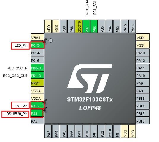
Setup PA0, PA1 and PC13 as GPIO_Output pins. Label PA0 as Test_Pin, PA1 as DS18B20_Pin and PC13 as LED_Pin.
Clock Configuration
Next, go to the Clock Configuration found at the top. This will open the following window. Here we will select the clock frequency.
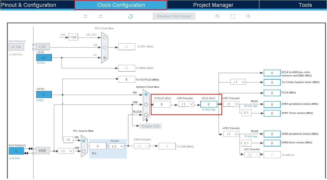
Set the system clock as 48 MHz. These are the configurations we have set:
Now we will save our file. Press Ctrl + S. The following window will appear. Click ‘Yes.’ This will generate a template code for you.

Another window will appear that will ask if you want to open the perspective. Click ‘Yes.’

STM32 DS18B20 Library
To acquire DS18B20 temperature readings with STM32 Blue Pill using STMCube IDE, we will require ds18b20 and onewire libraries. Let us show you how to include them in your project in order to access the APIs provided by each of them.
ds18b20.h
Go to Core > Inc and create a new file called ‘ds18b20.h‘ Copy the following code from this link and save it to this file.
onewire.h
Go to Core > Inc and create a new file called ‘onewire.h‘ Copy the following code from this link and save it to this file.
ds18b20.c
Go to Core > Inc and create a new file called ‘ds18b20.c‘ Copy the following code from this link and save it to this file.
onewire.c
Go to Core > Inc and create a new file called ‘onewire.c‘ Copy the following code from this link and save it to this file.
SSD1306 OLED Libraries
As we are working with an SSD1306 OLED with our STM32 Blue Pill, we will require the ssd1306.h and fonts.h libraries. These libraries will be used to access different functions that will enable us to display texts and numbers on the OLED in various ways.
ssd1306.h
Go to Core > Inc and create a new file called ‘ssd1306.h‘ Copy the following code from this link and save it to this file.
fonts.h
Go to Core > Inc and create a new file called ‘fonts.h‘ Copy the following code from this link and save it to this file.
ssd1306.c
Similarly, head over to Core > Src and create a new file called ‘ssd1306.c‘ Copy the following code from this link and save it to this file.
fonts.c
Head over to Core > Src and create a new file called ‘fonts.c‘ Copy the following code from this link and save it to this file.
STM32 Blue Pill DS18B20 Sensor with OLED Code
Now let us look at our main.c file that was generated. Inside the main.c file, make sure the following code is part of your script by including the lines of code given below. We will use HAL library functions and DS18B20 libraries to access the sensor data and display them on the OLED using the fonts.h and ssd1306.h APIs.
#include "main.h"
#include "gpio.h"
#include "tim.h"
#include "onewire.h"
#include "ds18b20.h"
#include "string.h"
#include <stdio.h>
#include "fonts.h"
#include "ssd1306.h"

I2C_HandleTypeDef hi2c1;

TIM_HandleTypeDef htim1;

void SystemClock_Config(void);
static void MX_I2C1_Init(void);

float temperature;
char string[64];

int main(void)
{
  HAL_Init();
  SystemClock_Config();
  MX_GPIO_Init();
  MX_TIM1_Init();
  MX_I2C1_Init();

  SSD1306_Init();

  DS18B20_Init(DS18B20_Resolution_12bits);
  HAL_GPIO_WritePin(TEST_Pin_GPIO_Port, TEST_Pin_Pin, 0);

  while (1)
  {
	  DS18B20_ReadAll();
	  HAL_GPIO_WritePin(TEST_Pin_GPIO_Port, TEST_Pin_Pin, 1);
      DS18B20_StartAll();
      HAL_GPIO_WritePin(TEST_Pin_GPIO_Port, TEST_Pin_Pin, 0);
		uint8_t ROM_tmp[8];
		uint8_t i;

	for(i = 0; i < DS18B20_Quantity(); i++)
		{
			if(DS18B20_GetTemperature(i, &temperature))
			{
				DS18B20_GetROM(i, ROM_tmp);
				memset(string, 0, sizeof(string));
				sprintf(string, "%.2f C", temperature);
				SSD1306_GotoXY (20, 0);
				SSD1306_Puts ("Temperature", &Font_7x10, 1);
				SSD1306_GotoXY (25, 30);
				SSD1306_Puts (string, &Font_11x18, 1);
				SSD1306_UpdateScreen();
			}
		}
		HAL_Delay(1000);
		HAL_GPIO_TogglePin(LED_Pin_GPIO_Port, LED_Pin_Pin);
  }
}
How does the Code Works?
We start off by including the necessary libraries for this project which include the DS18B20 libraries for the sensor functionality and fonts.h and ssd1306.h libraries for the OLED functionality.
#include "main.h"
#include "onewire.h"
#include "ds18b20.h"
#include "string.h"
#include <stdio.h>
#include "fonts.h"
#include "ssd1306.h"
Moreover, we include gpio.h and tim.h files inside our main.c file. As our DS18B20 libraries use these files, hence we created separate gpio.h, gpio.c, tim.h and tim.c files inside our project with the generated gpio and timer functions.
#include "gpio.h"
#include "tim.h"
main()
Inside the main function, first all the peripherals are initialized, system clock is configured and all the configured peripherals are initialized.
  HAL_Init();
  SystemClock_Config();
  MX_GPIO_Init();
  MX_TIM1_Init();
  MX_I2C1_Init();
Next, we initialize the OLED. We use the SSD1306_Init() function for initialization.
SSD1306_Init();Initialize the DS18B20 sensor with 12 bits resolution by calling DS18B20_Init() and specifiying the sensor resolution as a parameter inside this function. Moreover, we set the state of the Test_Pin as low.
  DS18B20_Init(DS18B20_Resolution_12bits);
  HAL_GPIO_WritePin(TEST_Pin_GPIO_Port, TEST_Pin_Pin, 0);
Read and Display Sensor Data
Inside the infinite while loop, we start accessing the temperature readings from the DS18B20 sensor and display them on the OLED screen.
  while (1)
  {
	  DS18B20_ReadAll();
	  HAL_GPIO_WritePin(TEST_Pin_GPIO_Port, TEST_Pin_Pin, 1);
      DS18B20_StartAll();
      HAL_GPIO_WritePin(TEST_Pin_GPIO_Port, TEST_Pin_Pin, 0);
		uint8_t ROM_tmp[8];
		uint8_t i;

	for(i = 0; i < DS18B20_Quantity(); i++)
		{
			if(DS18B20_GetTemperature(i, &temperature))
			{
				DS18B20_GetROM(i, ROM_tmp);
				memset(string, 0, sizeof(string));
				sprintf(string, "%.2f C", temperature);
				SSD1306_GotoXY (20, 0);
				SSD1306_Puts ("Temperature", &Font_7x10, 1);
				SSD1306_GotoXY (25, 30);
				SSD1306_Puts (string, &Font_11x18, 1);
				SSD1306_UpdateScreen();
			}
		}
		HAL_Delay(1000);
		HAL_GPIO_TogglePin(LED_Pin_GPIO_Port, LED_Pin_Pin);
  }
To start reading the DS18B20 sensor, we first call the function DS18B20_ReadAll(). This reads the temperatures of all the connected sensors in a loop. Then we set the state of the Test_Pin to high and call DS18B20_Start() before setting the state of the Test_Pin to low again. The DS18B20_Start() function resets the onewire bus, skips the ROM command and starts the conversion on all the sensors.
DS18B20_ReadAll();
HAL_GPIO_WritePin(TEST_Pin_GPIO_Port, TEST_Pin_Pin, 1);
DS18B20_StartAll();
HAL_GPIO_WritePin(TEST_Pin_GPIO_Port, TEST_Pin_Pin, 0);
After that we run a for loop to obtain the temperature readings using DS18B20_GetTemperature() and display them on the OLED. In our case, the loop runs once as we are using a single DS18B20 sensor.
If the DS18B20_GetTemperature() Then we convert the float temperature variable to string consisting of reading and its unit and display them on the OLED.
To display the sensor data on the OLED, first, we will set the x and the y axis position from where the text should start. SSD1306_gotoXY() function is used to set the write pointers. We have passed (20,0) as the parameter to display the text ‘Temperature’. We use SSD1306_Puts() function to display the temperature readings along with its unit on the screen at starting x-axis and y-axis at (25,30). This function takes in three parameters which is the string to be displayed, the font name and the color of the text. Additionally, call SSD1306_UpdateScreen() to display the text on the screen. The readings will update on the screen after every second and the LED_Pin connected at PC13 (on-board LED) also toggles.
	for(i = 0; i < DS18B20_Quantity(); i++)
		{
			if(DS18B20_GetTemperature(i, &temperature))
			{
				DS18B20_GetROM(i, ROM_tmp);
				memset(string, 0, sizeof(string));
				sprintf(string, "%.2f C", temperature);
				SSD1306_GotoXY (20, 0);
				SSD1306_Puts ("Temperature", &Font_7x10, 1);
				SSD1306_GotoXY (25, 30);
				SSD1306_Puts (string, &Font_11x18, 1);
				SSD1306_UpdateScreen();
			}
		}
		HAL_Delay(1000);
		HAL_GPIO_TogglePin(LED_Pin_GPIO_Port, LED_Pin_Pin);
  }
main.c file
This is how a complete main.c file will be after modification.
#include "main.h"
#include "gpio.h"
#include "tim.h"
#include "onewire.h"
#include "ds18b20.h"
#include "string.h"
#include <stdio.h>
#include "fonts.h"
#include "ssd1306.h"

I2C_HandleTypeDef hi2c1;

TIM_HandleTypeDef htim1;

void SystemClock_Config(void);
static void MX_I2C1_Init(void);

float temperature;
char string[64];

int main(void)
{
  HAL_Init();
  SystemClock_Config();
  MX_GPIO_Init();
  MX_TIM1_Init();
  MX_I2C1_Init();

  SSD1306_Init();

  DS18B20_Init(DS18B20_Resolution_12bits);
  HAL_GPIO_WritePin(TEST_Pin_GPIO_Port, TEST_Pin_Pin, 0);

  while (1)
  {
	  DS18B20_ReadAll();
	  HAL_GPIO_WritePin(TEST_Pin_GPIO_Port, TEST_Pin_Pin, 1);
      DS18B20_StartAll();
      HAL_GPIO_WritePin(TEST_Pin_GPIO_Port, TEST_Pin_Pin, 0);
		uint8_t ROM_tmp[8];
		uint8_t i;

	for(i = 0; i < DS18B20_Quantity(); i++)
		{
			if(DS18B20_GetTemperature(i, &temperature))
			{
				DS18B20_GetROM(i, ROM_tmp);
				memset(string, 0, sizeof(string));
				sprintf(string, "%.2f C", temperature);
				SSD1306_GotoXY (20, 0);
				SSD1306_Puts ("Temperature", &Font_7x10, 1);
				SSD1306_GotoXY (25, 30);
				SSD1306_Puts (string, &Font_11x18, 1);
				SSD1306_UpdateScreen();
			}
		}
		HAL_Delay(1000);
		HAL_GPIO_TogglePin(LED_Pin_GPIO_Port, LED_Pin_Pin);
  }
}

/**
  * @brief System Clock Configuration
  * @retval None
  */
void SystemClock_Config(void)
{
  RCC_OscInitTypeDef RCC_OscInitStruct = {0};
  RCC_ClkInitTypeDef RCC_ClkInitStruct = {0};

  /** Initializes the RCC Oscillators according to the specified parameters
  * in the RCC_OscInitTypeDef structure.
  */
  RCC_OscInitStruct.OscillatorType = RCC_OSCILLATORTYPE_HSE;
  RCC_OscInitStruct.HSEState = RCC_HSE_ON;
  RCC_OscInitStruct.HSEPredivValue = RCC_HSE_PREDIV_DIV1;
  RCC_OscInitStruct.HSIState = RCC_HSI_ON;
  RCC_OscInitStruct.PLL.PLLState = RCC_PLL_ON;
  RCC_OscInitStruct.PLL.PLLSource = RCC_PLLSOURCE_HSE;
  RCC_OscInitStruct.PLL.PLLMUL = RCC_PLL_MUL6;
  if (HAL_RCC_OscConfig(&RCC_OscInitStruct) != HAL_OK)
  {
    Error_Handler();
  }
  /** Initializes the CPU, AHB and APB buses clocks
  */
  RCC_ClkInitStruct.ClockType = RCC_CLOCKTYPE_HCLK|RCC_CLOCKTYPE_SYSCLK
                              |RCC_CLOCKTYPE_PCLK1|RCC_CLOCKTYPE_PCLK2;
  RCC_ClkInitStruct.SYSCLKSource = RCC_SYSCLKSOURCE_PLLCLK;
  RCC_ClkInitStruct.AHBCLKDivider = RCC_SYSCLK_DIV1;
  RCC_ClkInitStruct.APB1CLKDivider = RCC_HCLK_DIV2;
  RCC_ClkInitStruct.APB2CLKDivider = RCC_HCLK_DIV1;

  if (HAL_RCC_ClockConfig(&RCC_ClkInitStruct, FLASH_LATENCY_1) != HAL_OK)
  {
    Error_Handler();
  }
}

/**
  * @brief I2C1 Initialization Function
  * @param None
  * @retval None
  */
static void MX_I2C1_Init(void)
{

  /* USER CODE BEGIN I2C1_Init 0 */

  /* USER CODE END I2C1_Init 0 */

  /* USER CODE BEGIN I2C1_Init 1 */

  /* USER CODE END I2C1_Init 1 */
  hi2c1.Instance = I2C1;
  hi2c1.Init.ClockSpeed = 400000;
  hi2c1.Init.DutyCycle = I2C_DUTYCYCLE_2;
  hi2c1.Init.OwnAddress1 = 0;
  hi2c1.Init.AddressingMode = I2C_ADDRESSINGMODE_7BIT;
  hi2c1.Init.DualAddressMode = I2C_DUALADDRESS_DISABLE;
  hi2c1.Init.OwnAddress2 = 0;
  hi2c1.Init.GeneralCallMode = I2C_GENERALCALL_DISABLE;
  hi2c1.Init.NoStretchMode = I2C_NOSTRETCH_DISABLE;
  if (HAL_I2C_Init(&hi2c1) != HAL_OK)
  {
    Error_Handler();
  }
  /* USER CODE BEGIN I2C1_Init 2 */

  /* USER CODE END I2C1_Init 2 */

}

/**
  * @brief TIM1 Initialization Function
  * @param None
  * @retval None
  */


/**
  * @brief GPIO Initialization Function
  * @param None
  * @retval None
  */


/* USER CODE BEGIN 4 */

/* USER CODE END 4 */

/**
  * @brief  This function is executed in case of error occurrence.
  * @retval None
  */
void Error_Handler(void)
{
  /* USER CODE BEGIN Error_Handler_Debug */
  /* User can add his own implementation to report the HAL error return state */
  while(1)
  {
  }
  /* USER CODE END Error_Handler_Debug */
}

#ifdef  USE_FULL_ASSERT
/**
  * @brief  Reports the name of the source file and the source line number
  *         where the assert_param error has occurred.
  * @param  file: pointer to the source file name
  * @param  line: assert_param error line source number
  * @retval None
  */
void assert_failed(uint8_t *file, uint32_t line)
{
  /* USER CODE BEGIN 6 */
  /* User can add his own implementation to report the file name and line number,
     ex: printf("Wrong parameters value: file %s on line %d\r\n", file, line) */
  /* USER CODE END 6 */
}
#endif /* USE_FULL_ASSERT */
Save the main.c file after modifying it. Now we are ready to build our project.
Building the Project
To build our project press Ctrl + B or go to Project > Build All.
Your project will start building. After a few moments, your project will be successfully built if there are no errors.
Connecting ST-Link Programmer with STM32
Now as we have successfully built our project let us move ahead and upload the code to our STM32 board. First, we will have to connect our Blue Pill STM32 with an ST-Link programmer. We will be using ST-Link V2.

This will provide an interface between our computer and our STM32 board. It consists of 10 pins. We will be using pin2 SWDIO, pin6 SWCLK, pin4 GND, and pin8 3.3V to connect with our STM32 board. The SWDIO is the data input/output pin and the SWCLK is the clock pin. Follow the pin configuration given on ST-LINK V2 to identify each pin.
Follow the table below to connect both devices correctly.
| STM32 | ST-LINK V2 |
|---|---|
| VCC 3.3V pin | pin8 3.3V |
| SWDIO pin | pin2 SWDIO |
| SWCLK pin | pin6 SWCLK |
| GND pin | pin4 GND |

Additionally, move the BOOT jumper to the right to enable the microcontroller to go into programming mode.

- Now connect your ST-LINK V2 with your computer via the USB port. Both devices will power ON.
- Next press the RUN button in the IDE. The ‘Edit configuration’ window will open up. Click ‘OK’.
- After a few moments, the code will be successfully sent to the STM32 board. Otherwise, press the RESET button on your STM32 board.
- Now to bring the Blue pill back to normal mode make sure you bring the BOOT jumper back to its place.
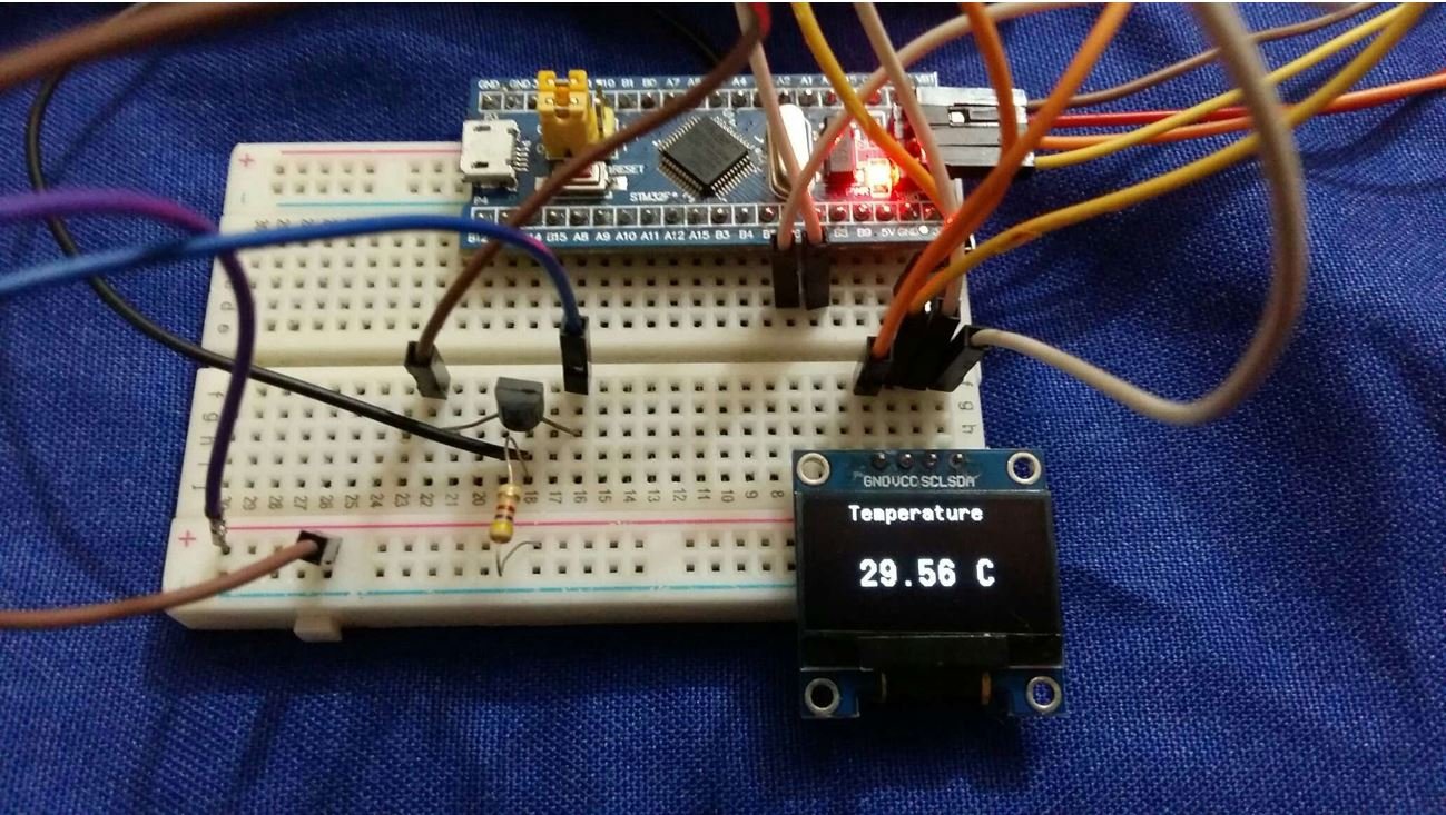
Once the code is uploaded to the board, the OLED will start displaying the temperature readings on the screen, which will update to new values after every second.
Watch the video below:
You may also like to read:
Fantastic Site, so full of information, what a pleasure!
This is, Excellency, my passion. So great
Hello and thank you for your work.
You don’t mention the purpose of the Test_Pin and where it is connected on the board. Please don’t name pins Test_Pin 🙂
Why is there Test_Pin and DS18B20_Pin for a OneWire application ?
I would also like to know what is the purpose of TEST_Pin, especially I get a build error:
../Core/Src/main.c:116:22: error: ‘TEST_Pin_GPIO_Port’ undeclared (first use in this function);
Regards
W.P.
Thank you very much very explanatory.
If the files gpio.h, tim.h are not created check this:
https://community.st.com/t5/stm32cubemx-mcu/usart-h-usart-c-and-the-gpio-h-gpio-c-files-are-missing/td-p/166257
thank u so much nice content