In this STM32 Blue Pill user guide, we will learn how to send and receive data through SPI communication protocol between a master STM32 and a slave STM32 board. We will particularly focus on showing you three methods to receive data via SPI communication that involves polling, DMA, and interrupt methods. Therefore, we will create and build three projects in STM32 Cube IDE to effectively demonstrate all three methods where we will send a string of message from the SPI master which acts as a transmitter to the SPI slave which acts as the receiver. So let us begin!
Recommended Components
The following components are used in this project or are helpful for getting started with STM32 Blue Pill development.
| Component | How it’s used in this project | Buy on Amazon |
|---|---|---|
| STM32F103C8T6 Blue Pill Board (x2) | Two boards act as the SPI master (transmitter) and slave (receiver). | Check Price |
| ST-Link V2 Programmer | SWD programmer/debugger used to flash code onto both boards. | Check Price |
| USB-TTL / FTDI Converter | Lets the slave print received data to a serial terminal. | Check Price |
| Breadboard & Jumper Wires | For wiring the SPI bus between the two boards. | Check Price |
As an Amazon Associate we earn from qualifying purchases. Prices and availability are accurate as of the date/time indicated and are subject to change.
STM32 Blue Pill SPI Transmitter
Before moving ahead to SPI receiver, let us first briefly go over the different types of modes of transmitting data via the SPI bus.
| Polling | SPI data transmission through the polling method occurs in blocking mode. When the data transmission starts, the CPU stops until all the data is transmitted. After the data transmission completes, the CPU starts again and continues with the execution of the main code. The data is sent in bytes where there the CPU waits until the current byte is fully transmitted and then sends the next one. |
| Interrupt | In this scenario, the SPI data transmission occurs in non-blocking mode. Unlike the polling method, the CPU does not stop but continues the execution of the main code. The completion of data transmission marks the triggering of the interrupt. This enables the CPU to send the next byte of data. Using interrupt method with high data rate can however overload the CPU. |
| DMA | The DMA method is more efficient than polling or interrupt methods. In this scenario, data transmission occurs in non-blocking mode where the DMA transfers the data from the peripheral to the memory directly. The CPU is not involved as was the case in polling and interrupt. |
| Timer Interrupt | A periodic timer interrupt can also be used to transfer data via the SPI bus. In this case, each data byte is transferred when the timer overflows according to the timer overflow period set. This method is fine to use in applications where the sampling rate is less in which case the user can set an appropriate sample period to set the timer. The CPU is still involved in this process as the interrupt signal has to be monitored and the data is to be read from the memory and sent to the SPI peripheral. |
| Timer Interrupt & DMA | Using timer interrupt with DMA resolves the involvement of the CPU for data transmission. When the timer overflow occurs, the DMA gets triggered hence now it is responsible for data transfers. Different data sampling rates can easily be configured by setting an appropriate timer period. |
SPI Data Transmission STM32 Blue Pill Master and Slave Configuration
As we mentioned before, we will set up an STM32 Blue Pill master and slave that will communicate via the SPI bus. The SPI master will be the transmitter that will send data to the SPI slave which will be the receiver. The STM32 Blue Pill master and slave boards will be connected with the SPI pins. The STM32 Blue Pill features two sets of SPI channels. We will configure SPI1 channel for this guide. Moreover, the slave Blue Pill will be connected with a FTDI programmer/USB-TTL converter. By using a USB-TTL converter with the receiver, we will be able to display the received data on the serial port terminal.
We will require the following components for this project:
- Two STM32 Blue Pill boards
- FTDI Programmer/ USB to TTL converter
- Connecting Wires
Hardware Setup
As we are using SPI channel 1 pins which translate to PA5 as the SCK pin and PA7 as the MOSI pin. Hence these two pins will be used for SPI communication between the two boards. Connect the SCK and MOSI pins of both boards together along with common ground.
We will use the UART2 module pins for the receiver. VCC of the programmer is connected with 3.3V from the Blue pill and both the GND of the devices are connected together. PA2 is the TX2 pin of STM32 and PA3 is the RX2 pin of STM32. Connect the RX pin of STM32 with TX pin of FTDI and TX pin of STM32 with RX pin of FTDI converter.
The schematic diagram below shows the connections of the SPI master and slave devices that we will use for our projects.

STM32 Blue Pill SPI Master as a Transmitter Project
First, we will set up our STM32 Blue Pill SPI master as a transmitter in Cube IDE. Open the IDE and head over to a new project.
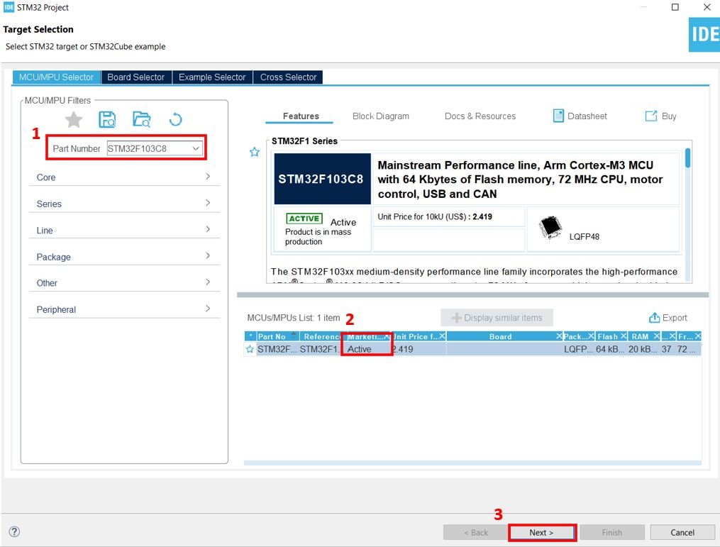
Then for the target selection, specify the STM32 Blue Pill board number. After that click on any column as shown in the picture below. Then click the ‘Next’ button.
Specify the name of your project then click ‘Finish’ to complete the setup of your project.
Firstly go to System Core > RCC then select ‘Crystal/Ceramic Resonator’ in from the High Speed Clock feature.
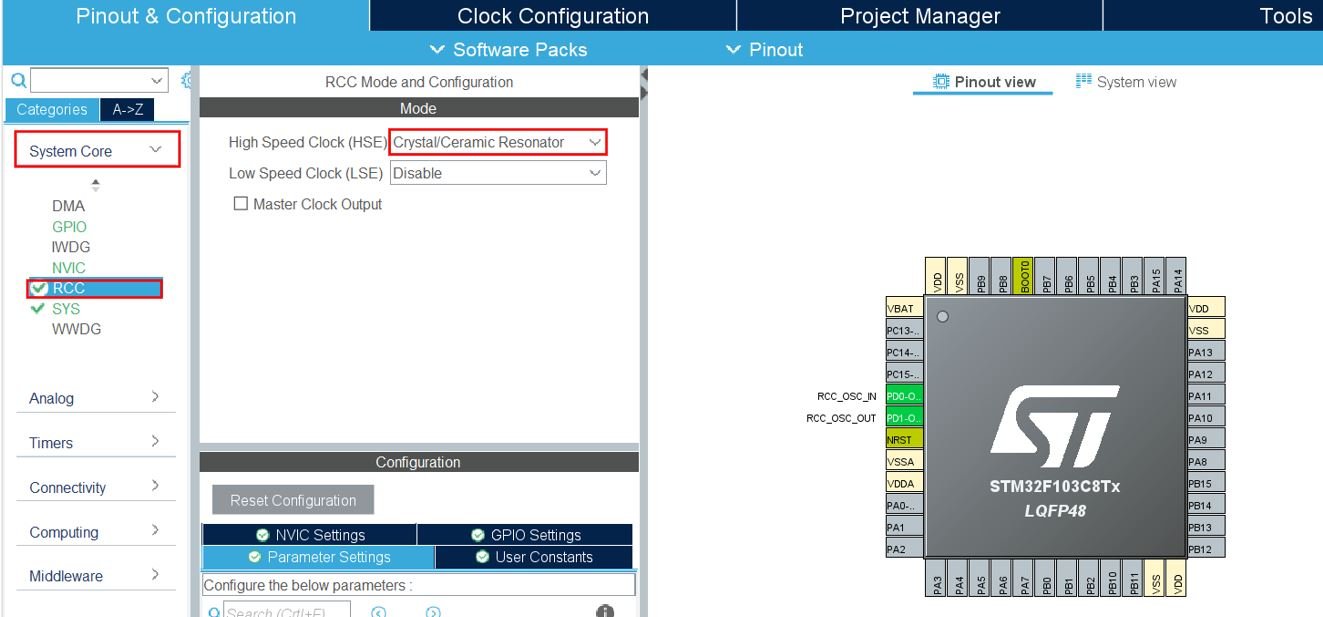
Now we have enabled the RCC external clock source.
Clock Configuration
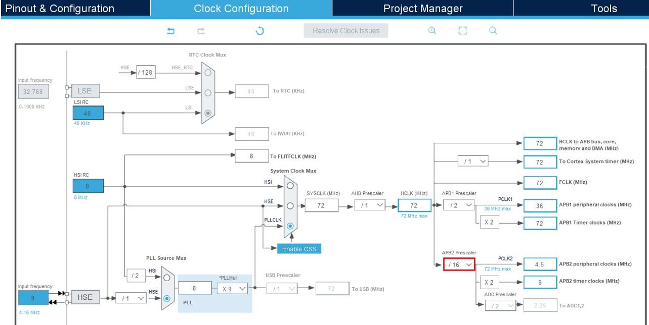
Next go to the Clock Configuration found at the top. This will open the following window. Here we will select the clock frequency.
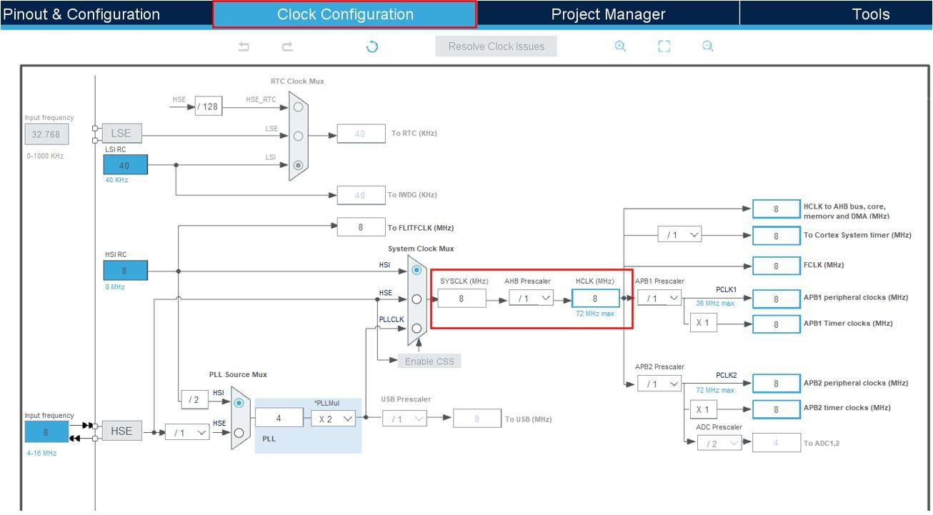
You can specify your system clock. We will set it as 72MHz. These are the configurations we have set. The APB2 Prescaler is set to 16. This is to make sure the SPI bit rate is slower than the UART baud rate so that the receiver board is easily able to send the data it receives.
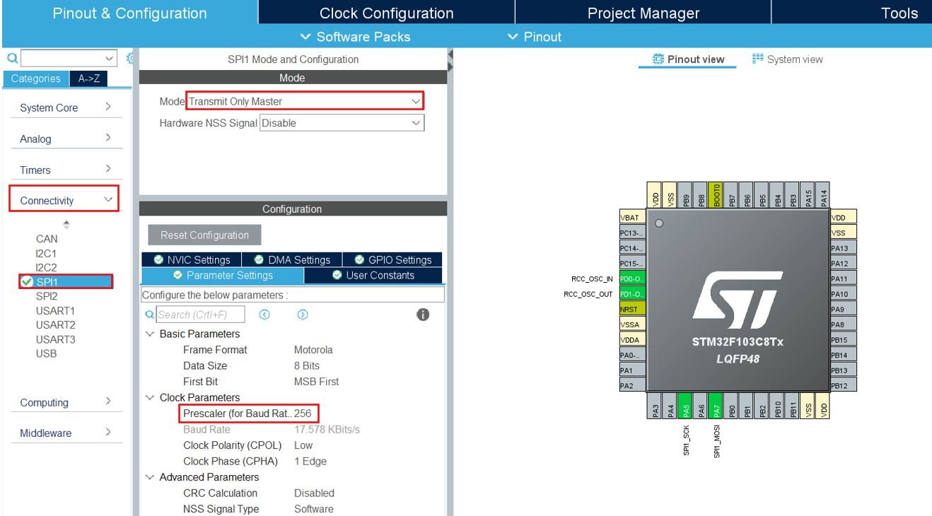
Now head over to Connectivity > SPI1 to enable SPI1 module. This enables PA5 as the SPI SCK pin and PA7 as the SPI MOSI pin. We have set the mode as ‘Transmit Only Master.’ The prescaler is set as 256.
Now we will save our file. Press Ctrl + S. The following window will appear. Click ‘Yes.’ This will generate a template code for you.

Another window will appear that will ask if you want to open the perspective. Click ‘Yes.’

STM32 Blue Pill SPI Master as a Transmitter Code
A main.c file gets generated. Inside the main.c file, make sure the following code is part of your script by including the lines of code given below.
#include "main.h"
SPI_HandleTypeDef hspi1;
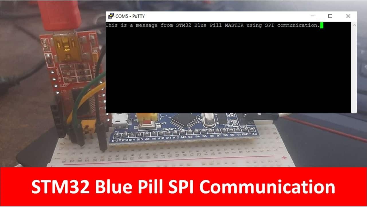
uint8_t TX_Data[] = "This is a message from STM32 Blue Pill MASTER using SPI communication.";
void SystemClock_Config(void);
static void MX_GPIO_Init(void);
static void MX_SPI1_Init(void);
int main(void)
{
HAL_Init();
SystemClock_Config();
MX_GPIO_Init();
MX_SPI1_Init();
HAL_SPI_Transmit(&hspi1, TX_Data, sizeof(TX_Data), 5000);
while (1)
{
}
}
We are using the polling method to transmit data using the SPI bus. To transmit an amount of data in blocking mode, we call the function HAL_SPI_Transmit(). This function takes in four parameters. The first parameter is the pointer to the SPI_HandleTypeDef structure that holds the configuration parameters for SPI module. The second parameter is the pointer to the data buffer. The third parameter is the size of the data buffer. The last parameter is the timeout duration in milliseconds which we have set as 5 seconds.
HAL_SPI_Transmit(&hspi1, TX_Data, sizeof(TX_Data), 5000);Here, we are transmitting the data buffer ‘TX_Data’ which contains the string “This is a message from STM32 Blue Pill MASTER using SPI communication.” via the SPI1bus.
Save the main.c file after modifying it. Now we are ready to build our project.
Building the Project
To build our project press Ctrl + B or go to Project > Build All.
Your project will start building. After a few moments, your project will be successfully built if there are no errors.
Connecting ST-Link Programmer with STM32
Now as we have successfully built our project let us move ahead and upload the code to our STM32 board. To do that, first we will have to connect our Blue Pill STM32 with a ST-Link programmer. We will be using ST-Link V2.

This will provide an interface between our computer and our STM32 board. It consists of 10 pins. We will be using pin2 SWDIO, pin6 SWCLK, pin4 GND, and pin8 3.3V to connect with our STM32 board. The SWDIO is the data input/output pin and the SWCLK is the clock pin. Follow the pin configuration given on the ST-LINK V2 to identify each pin.
Follow the table below to connect both devices correctly.
| STM32 | ST-LINK V2 |
| VCC 3.3V pin | pin8 3.3V |
| SWDIO pin | pin2 SWDIO |
| SWCLK pin | pin6 SWCLK |
| GND pin | pin4 GND |

Additionally move the BOOT jumper to the right to enable the microcontroller to go into programming mode.

- Now connect your ST-LINK V2 with your computer via the USB port. Both the devices will power ON.
- Next press the RUN button in the IDE. The ‘Edit configuration’ window will open up. Click ‘OK’.
- After a few moments, the code will be successfully sent to the STM32 board. Otherwise, press the RESET button on your STM32 board.
- Now to bring the Blue pill back to normal mode make sure you bring the BOOT jumper back at its place.
Our SPI Master is ready to transmit the message. Let us setup the SPI slave to receive the message. We will show you three different modes in which we can set up our SPI slave to receive the data from the transmitter.
Method 1: STM32 Blue Pill SPI Slave as a Receiver using Polling
Now let us build our projects for the SPI slave using the polling, interrupt and DMA methods to show you the differences. We will start off by configuring the SPI1 module for the receiver in polling mode.
So let us begin the project! Create a new project in STM32 Cube IDE and follow similar steps as before.
- Specify the target selection and then name of your project to complete the setup of your project.
- Now go to System Core > RCC then select ‘Crystal/Ceramic Resonator’ in from the High Speed Clock feature. Now we have enabled the RCC external clock source.
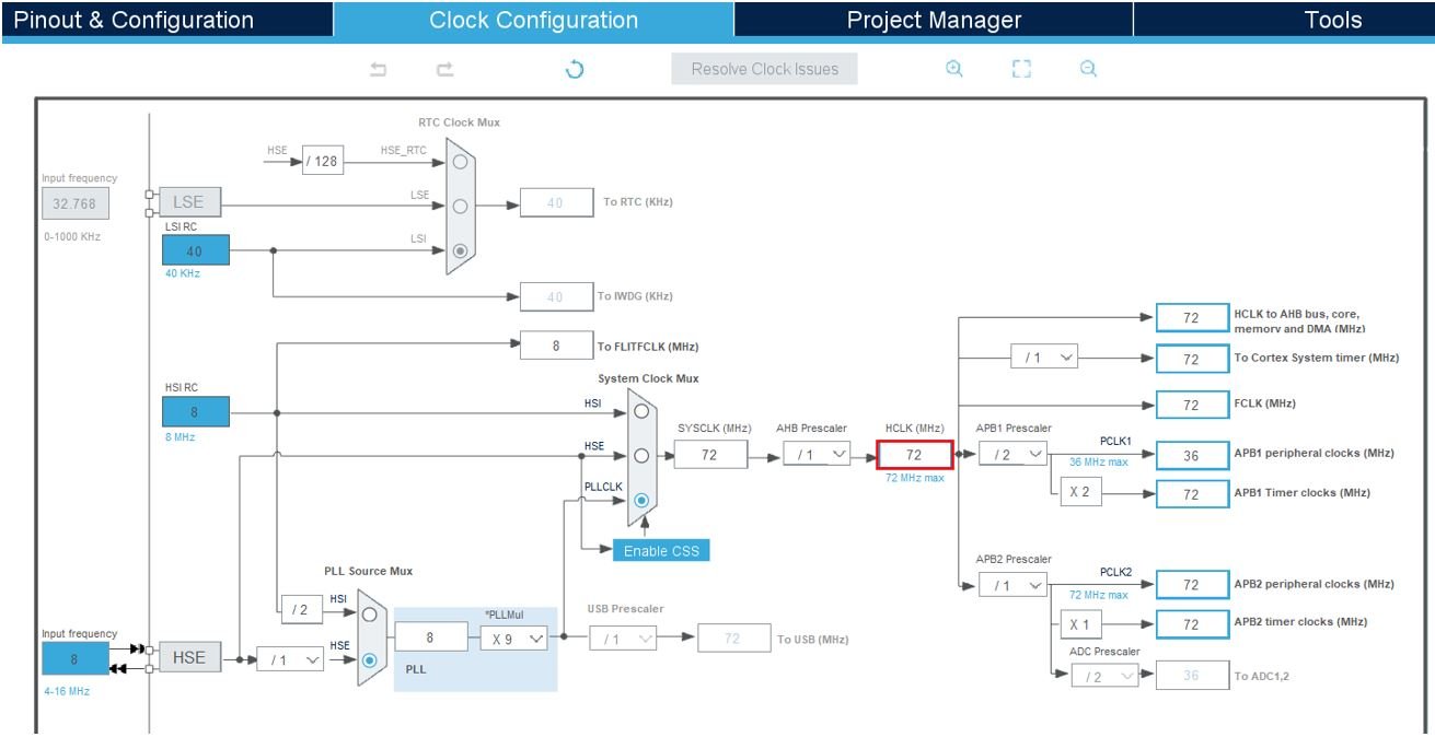
- Next go to the Clock Configuration found at the top. This will open the following window. Here we will select the clock frequency. You can specify your system clock. We will set it as 72MHz.
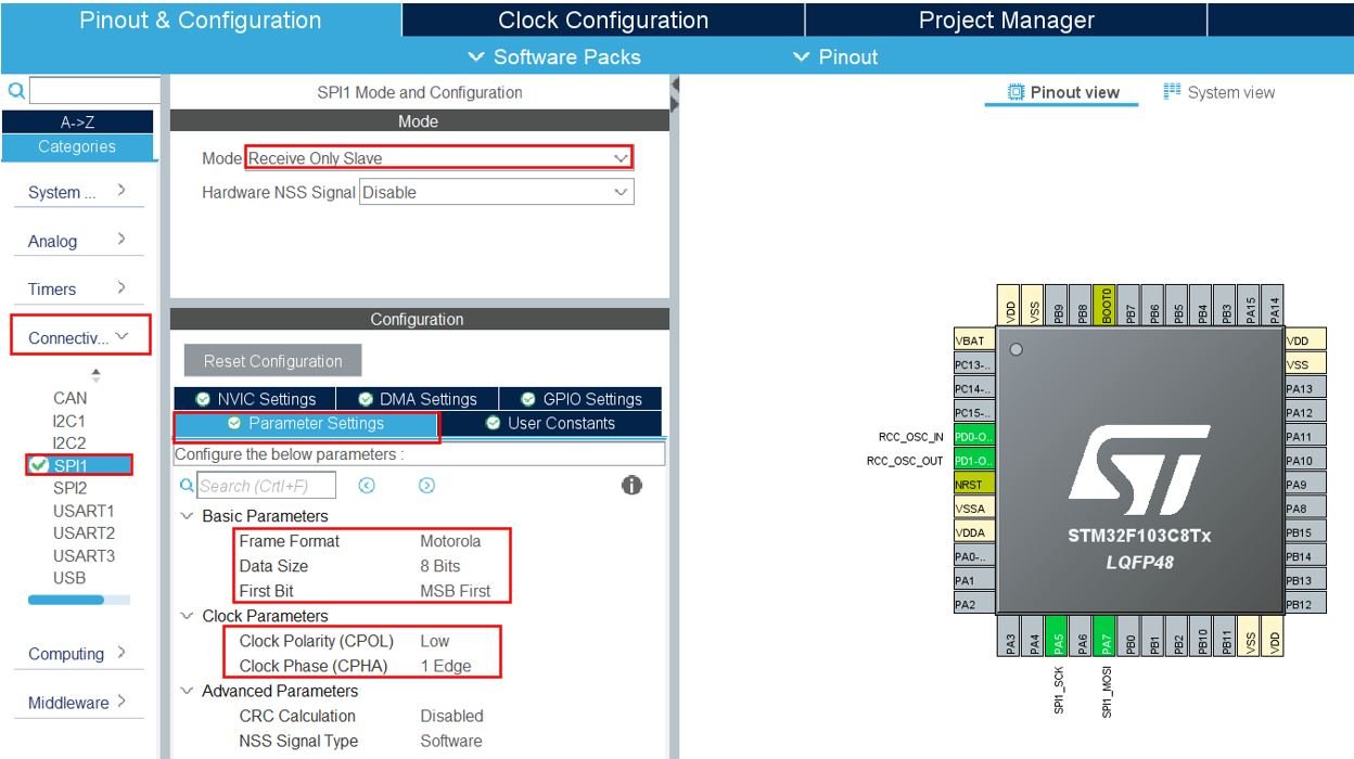
- Now head over to Connectivity > SPI1 to enable SPI1 module. This enables PA5 as the SPI SCK pin and PA7 as the SPI MOSI pin. We have set the mode as ‘Receive Only Slave.’ Make sure the clock edge, polarity, data size and order are configured same for both the devices.
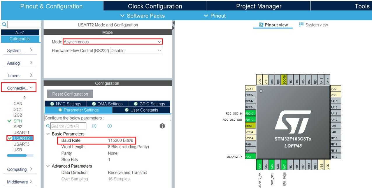
- Head over to Connectivity > USART2 and set the mode as ‘Asynchronous’ and the baud rate as 115200.
Now save the file and open the perspective.
STM32 Blue Pill SPI Slave as a Receiver in Polling Mode Code
A main.c file gets generated. Inside the main.c file, make sure the following code is part of your script by including the lines of code given below.
#include "main.h"

SPI_HandleTypeDef hspi1;

UART_HandleTypeDef huart2;
uint8_t RX_Data[70] = {0};

void SystemClock_Config(void);
static void MX_GPIO_Init(void);
static void MX_SPI1_Init(void);
static void MX_USART2_UART_Init(void);

int main(void)
{
  HAL_Init();
  SystemClock_Config();

  MX_GPIO_Init();
  MX_SPI1_Init();
  MX_USART2_UART_Init();

  HAL_SPI_Receive(&hspi1, RX_Data, sizeof(RX_Data), 5000);
  HAL_UART_Transmit(&huart2, RX_Data, sizeof(RX_Data), 5000);

  while (1)
  {

  }

}
We first create a buffer called ‘RX_Data’ with the same size as the incoming data buffer.
uint8_t RX_Data[70] = {0};Inside the main() function, after configuring clock and enabling the peripherals, we will receive an amount of data in blocking mode by calling HAL_SPI_Receive(). This function takes in four parameters. The first parameter is the pointer to the SPI_HandleTypeDef structure that holds the configuration parameters for SPI module. The second parameter is the pointer to the data buffer. The third parameter is the size of the data that will be received. The fourth parameter is the timeout duration which is set as 5s.
HAL_SPI_Receive(&hspi1, RX_Data, sizeof(RX_Data), 5000);After receiving the incoming data buffer, the string is displayed in the serial port terminal through HAL_UART_Transmit() function.
HAL_UART_Transmit(&huart2, RX_Data, sizeof(RX_Data), 5000);Save the main.c file after modifying it, build the project and run it.
Demonstration
- After both SPI master and slave devices have been programmed with their respective codes, setup the hardware as mentioned previously. Connect the SPI pins of both the boards together and common ground them.
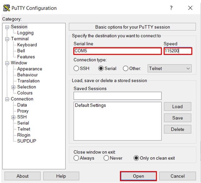
- Now connect the USB to TTL serial converter with the SPI slave STM32 board as mentioned previously. Open Device Manager and head over to Ports to check the COM port through which the USB-TTL converter is connected. It is COM5 in our case.

- Open a terminal on your system for example Putty. Set the correct speed and COM port and then press Open to establish a connection.
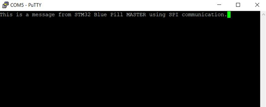
First press the Reset button of the receiver STM32. Before the timeout duration which is 5s, press the Reset button of the transmitter STM32. The data will be received over SPI by the SPI slave and then will be transmitted to the system’s serial port terminal through UART. You will be able to view the message received by the SPI slave in your terminal.
Method 2: STM32 Blue Pill SPI Slave as a Receiver using Interrupt
In this section we will show you how to receive data through the SPI bus using the interrupt mode.
Create a new project in STM32 Cube IDE and follow similar steps as before.
- Specify the target selection and then name of your project to complete the setup of your project.
- Now go to System Core > RCC then select ‘Crystal/Ceramic Resonator’ in from the High Speed Clock feature. Now we have enabled the RCC external clock source.
- Next go to the Clock Configuration found at the top. This will open the following window. Here we will select the clock frequency. You can specify your system clock. We will set it as 72MHz.
Enable SPI Module in Interrupt Mode
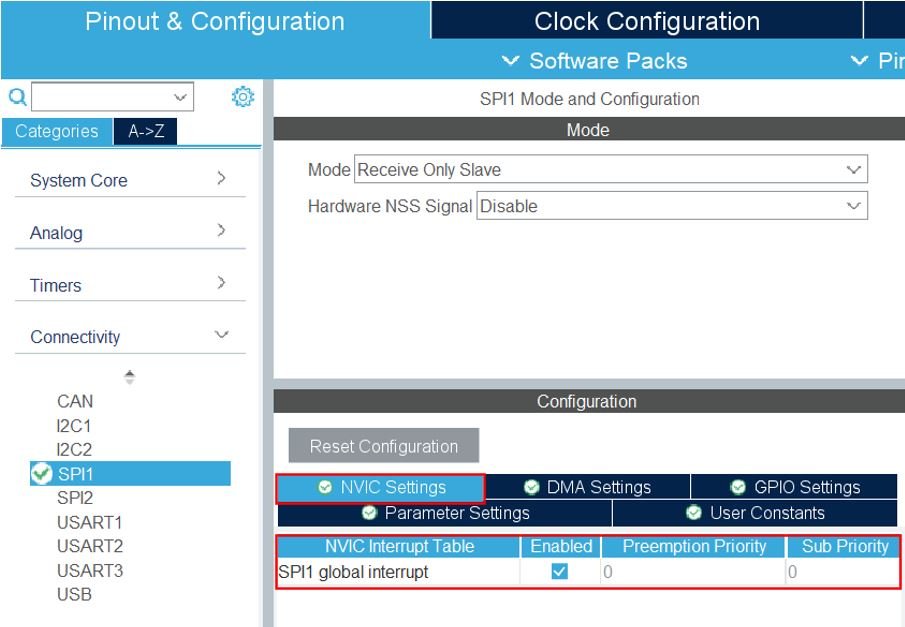
- Now head over to Connectivity > SPI1 to enable SPI1 module. This enables PA5 as the SPI SCK pin and PA7 as the SPI MOSI pin. We have set the mode as ‘Receive Only Slave.’ Make sure the clock edge, polarity, data size and order are configured same for both the devices. Now head over to NVICC Settings and enable the SPI1 global interrupt.
- Head over to Connectivity > USART2 and set the mode as ‘Asynchronous’ and the baud rate as 115200. Moreover, head over to the NVICC Settings and enable the USART2 global interrupt.

Now save the file and open the perspective.
STM32 Blue Pill SPI Slave as a Receiver in Interrupt Mode Code
A main.c file gets generated. Inside the main.c file, make sure the following code is part of your script by including the lines of code given below.
#include "main.h"

#define DATA_SIZE 70

SPI_HandleTypeDef hspi1;
UART_HandleTypeDef huart2;

uint8_t RX_Data[DATA_SIZE] = {0};

void SystemClock_Config(void);
static void MX_GPIO_Init(void);
static void MX_SPI1_Init(void);
static void MX_USART2_UART_Init(void);

int main(void)
{
  HAL_Init();

  SystemClock_Config();

  MX_GPIO_Init();
  MX_SPI1_Init();
  MX_USART2_UART_Init();

  HAL_SPI_Receive_IT(&hspi1, RX_Data, DATA_SIZE);

  while (1)
  {

  }

}

void HAL_SPI_RxCpltCallback(SPI_HandleTypeDef * hspi)
{
    HAL_SPI_Receive_IT(&hspi1, RX_Data, DATA_SIZE);
    HAL_UART_Transmit_IT(&huart2, RX_Data, DATA_SIZE);
}
We first create a buffer called ‘RX_Data’ with the same size as the incoming data buffer.
#define DATA_SIZE 70
uint8_t RX_Data[DATA_SIZE] = {0};
Inside the main() function, after configuring clock and enabling the peripherals, we will receive an amount of data in non-blocking mode with interrupt by calling HAL_SPI_Receive_IT(). This function takes in three parameters. The first parameter is the pointer to the SPI_HandleTypeDef structure that holds the configuration parameters for SPI module. The second parameter is the pointer to the data buffer. The third parameter is the size of the data that will be received.
HAL_SPI_Receive_IT(&hspi1, RX_Data, DATA_SIZE);The HAL_SPI_RxCpItCallback() function is the Rx transfer completed callback function. It also takes in the same parameter which is the pointer to the SPI_HandleTypeDef structure. Inside this callback, the HAL_SPI_Receive_IT() function is called to receive the data. After receiving the incoming data buffer, the string is displayed in the serial port terminal through HAL_UART_Transmit_IT() function.
This function is called when 70 bytes of data has been received by the SPI module setup in interrupt mode. This function will enable the process to repeat.
void HAL_SPI_RxCpltCallback(SPI_HandleTypeDef * hspi)
{
    HAL_SPI_Receive_IT(&hspi1, RX_Data, DATA_SIZE);
    HAL_UART_Transmit_IT(&huart2, RX_Data, DATA_SIZE);
}
Save the main.c file after modifying it, build the project and run it.
Method 3: STM32 Blue Pill SPI Slave as a Receiver using DMA
In this section we will show you how to receive data through the SPI bus using the DMA mode.
Create a new project in STM32 Cube IDE and follow similar steps as before.
- Specify the target selection and then name of your project to complete the setup of your project.
- Now go to System Core > RCC then select ‘Crystal/Ceramic Resonator’ in from the High Speed Clock feature. Now we have enabled the RCC external clock source.
- Next go to the Clock Configuration found at the top. This will open the following window. Here we will select the clock frequency. You can specify your system clock. We will set it as 72MHz.
Enable SPI Module in DMA Mode
- Now head over to Connectivity > SPI1 to enable SPI1 module. This enables PA5 as the SPI SCK pin and PA7 as the SPI MOSI pin. We have set the mode as ‘Receive Only Slave.’ Make sure the clock edge, polarity, data size and order are configured same for both the devices. Now head over to DMA Settings and add the DMA request. This is the only additional step that is to be performed.
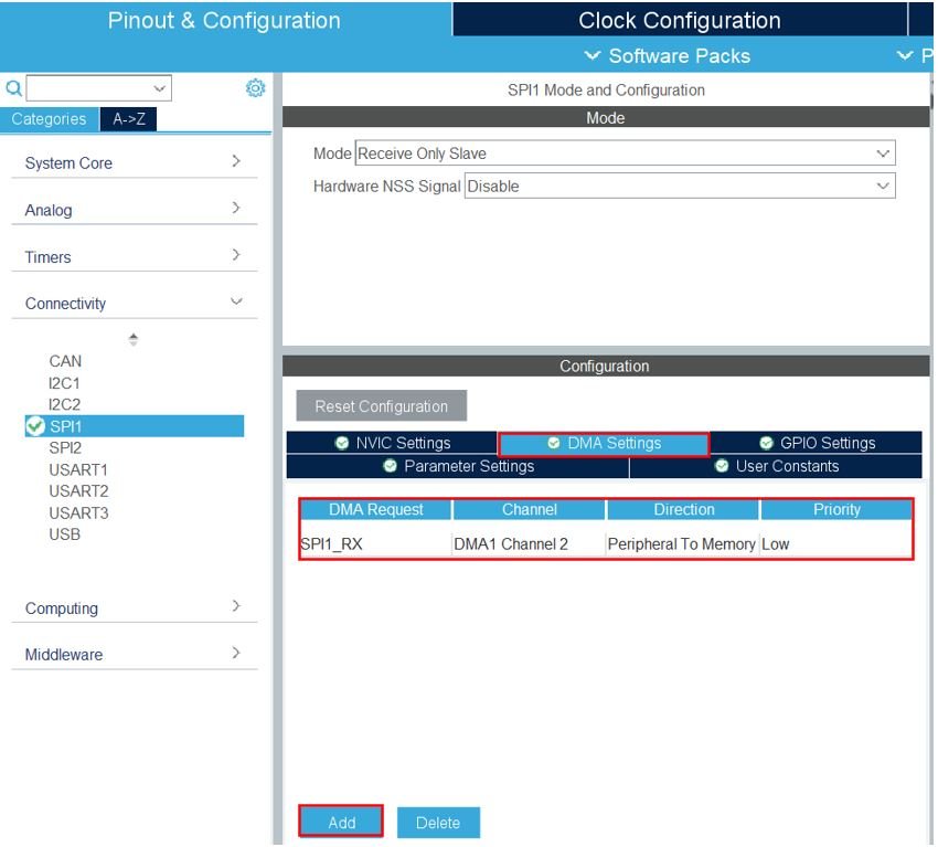
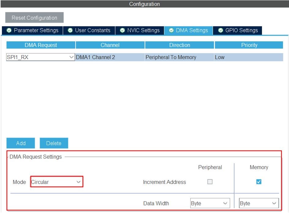
As we want to receive data, hence we added the DMA request ‘SPI1_RX.’ Here the data width is set as Byte. You have the option to select from byte, half word and word. Characters take one byte of memory hence we set the data width as ‘Byte’ as we will be receiving characters. We have set the mode as ‘Circular.’
- Head over to Connectivity > USART2 and set the mode as ‘Asynchronous’ and the baud rate as 115200. Moreover, head over to the NVICC Settings and enable the USART2 global interrupt.
Now save the file and open the perspective.
STM32 Blue Pill SPI Slave as a Receiver in DMA Mode Code
A main.c file gets generated. Inside the main.c file, make sure the following code is part of your script by including the lines of code given below.
#include "main.h"

#define DATA_SIZE 70

SPI_HandleTypeDef hspi1;
DMA_HandleTypeDef hdma_spi1_rx;

UART_HandleTypeDef huart2;

uint8_t RX_Data[DATA_SIZE] = {0};

void SystemClock_Config(void);
static void MX_GPIO_Init(void);
static void MX_SPI1_Init(void);
static void MX_DMA_Init(void);
static void MX_USART2_UART_Init(void);

int main(void)
{
  HAL_Init();
  SystemClock_Config();

  MX_GPIO_Init();
  MX_SPI1_Init();
  MX_DMA_Init();
  MX_USART2_UART_Init();

  HAL_SPI_Receive_DMA(&hspi1, RX_Data, DATA_SIZE);

  while (1)
  {
  }

}

void HAL_SPI_RxCpltCallback(SPI_HandleTypeDef * hspi)
{
    HAL_SPI_Receive_DMA(&hspi1, RX_Data, DATA_SIZE);
    HAL_UART_Transmit_IT(&huart2, RX_Data, DATA_SIZE);
}
We first create a buffer called ‘RX_Data’ with the same size as the incoming data buffer.
#define DATA_SIZE 70
uint8_t RX_Data[DATA_SIZE] = {0};
Inside the main() function, after configuring clock and enabling the peripherals, we will receive an amount of data in non-blocking mode with DMA by calling HAL_SPI_Receive_DMA(). This function takes in three parameters. The first parameter is the pointer to the SPI_HandleTypeDef structure that holds the configuration parameters for SPI module. The second parameter is the pointer to the data buffer. The third parameter is the size of the data that will be received.
HAL_SPI_Receive_DMA(&hspi1, RX_Data, DATA_SIZE);The HAL_SPI_RxCpItCallback() function is the Rx transfer completed callback function. It also takes in the same parameter which is the pointer to the SPI_HandleTypeDef structure. Inside this callback, the HAL_SPI_Receive_DMA() function is called to receive the data. After receiving the incoming data buffer, the string is displayed in the serial port terminal through HAL_UART_Transmit_IT() function.
void HAL_SPI_RxCpltCallback(SPI_HandleTypeDef * hspi)
{
    HAL_SPI_Receive_DMA(&hspi1, RX_Data, DATA_SIZE);
    HAL_UART_Transmit_IT(&huart2, RX_Data, DATA_SIZE);
}
Save the main.c file after modifying it, build the project, and run it. You will get an output similar to the first method.
You may also like to read:
- STM32 Blue Pill Timer in PWM Mode with LED Dimmer Example
- STM32 Blue Pill UART Communication Tutorial with CubeIDE and HAL Libraries
- STM32 Blue Pill Timer Interrupt with STM32Cube IDE and HAL Libraries
- STM32 Blue Pill External Interrupts with STM32Cube IDE and HAL Libraries
- STM32 Blue Pill Timer in PWM Mode with LED Dimmer Example