In this tutorial, we will learn to interface HC-05 Bluetooth module with STM32 Blue Pill using STM32CubeIDE and HAL libraries. We will use an android application to communicate with the STM32 Blue Pill through the HC-05 Bluetooth module. We will see an example to control an LED from the Android application using Bluetooth communication. The LED will be connected with an output GPIO pin of the Blue Pill and in effect, we will be controlling that pin.
Recommended Components
The following components are used in this project or are helpful for getting started with STM32 Blue Pill development.
| Component | How it’s used in this project | Buy on Amazon |
|---|---|---|
| STM32F103C8T6 Blue Pill Board | The STM32 board communicating with the HC-05 over UART. | Check Price |
| ST-Link V2 Programmer | SWD programmer/debugger used to flash code onto the Blue Pill. | Check Price |
| HC-05 Bluetooth Module | The Bluetooth module used for wireless serial communication. | Check Price |
| 5mm LED | The LED toggled from the Android app. | Check Price |
| Resistor Kit (incl. 220Ω) | A 220Ω current-limiting resistor for the LED. | Check Price |
| Breadboard & Jumper Wires | For wiring the module and LED to the Blue Pill. | Check Price |
As an Amazon Associate we earn from qualifying purchases. Prices and availability are accurate as of the date/time indicated and are subject to change.
The HC-05 Bluetooth device operates on UART communication. It uses serial communication to transmit and receive data serially over standard Bluetooth radio frequency. Therefore, we will use TX, RX pins of STM32 Blue Pill to connect with the module.
Bluetooth Terminal Application
We will use an android smartphone that will connect to our STM32 Blue Pill. So, make sure you have an android phone at hand. We will also use a Bluetooth terminal application to pair the two devices together.
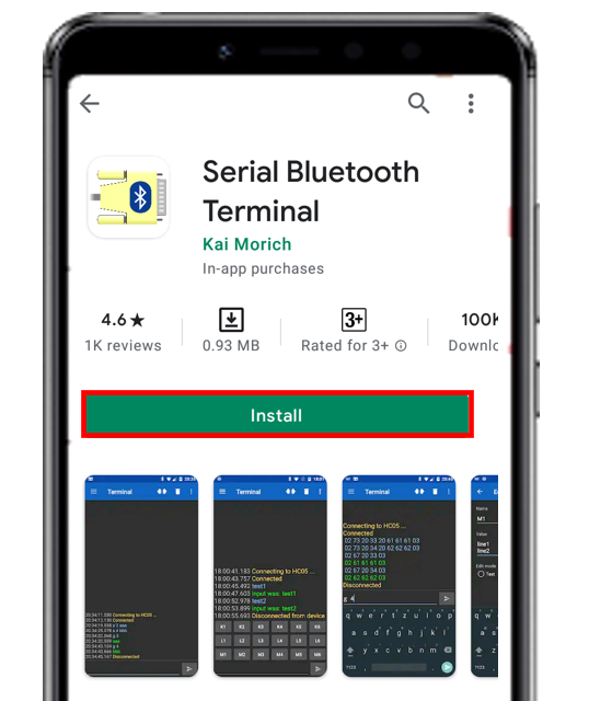
Go to the Play Store and download the application by the name: Serial Bluetooth terminal. This can be seen in the figure below.
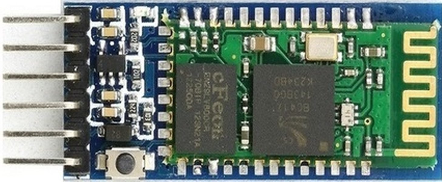
HC-05 Bluetooth Module Introduction
HC-05 is one of the commonly used Bluetooth devices that uses a UART communication protocol. The HC-05 Bluetooth is much different in features from all other Bluetooth devices because of its multiple pins and their functions. It has multiple pins for different methods which makes it unique as compared to others. The module normally operates at UART serial communication with TX and RX pins at 9600 baud rates. However, it can be programmed with AT commands and it supports 9600,19200,38400,57600,115200,230400,460800 baud rates.
Its CSR Bluecore 04-External single chip is already configured to communicate with other Bluetooth devices through serial communication. It offers a two-way communication method and the HC-05 can act as either slave and master. The Bluetooth module offers only short distance communications due to its limitation but still, most of the devices come with it due to its speed and security. The limitation of this device is that it doesn’t allow to transfer any kind of media.
In short, this module can be used to perform low-cost wireless communication between microcontrollers such as Arduino, TM4C123, Pic Microcontroller, Raspberry Pi, BeagleBone, STM32, and Arduino Mega, etc. Also, we can use it for communication between a microcontroller and PC or Android application. There are many Android applications available in the Google Play store which we can use to send and receive data to/from HC05. For this tutorial, we will use ‘Serial Bluetooth Terminal’ application that we installed previously.
Recommended Reading: HC-05 Bluetooth Module
HC-05 Bluetooth Module Pinout
The HC-05 comes with multiple pins and indicators, which helps to control different operations and view their states through indicators. This pinout diagram provides indications of all pins.
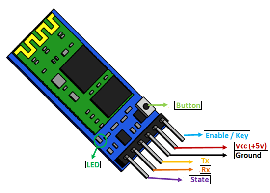
The table below also briefly describes the functionality of each pin.
| Pin | Description |
| VCC | The operating voltage range is 3.3 volts. But I/O pins can withstand voltage of up to 5 volts. |
| GND | Ground reference of both the microcontroller and HC-05 should be at the same level. |
| Tx | As discussed earlier, the HC-05 Bluetooth module uses UART communication to transmit data. This is a transmitter pin. The TX pin will be the data transfer pin of the module in UART. |
| Rx | This pin is a data receiving the pin in UART communication. It is used to receive data from the microcontroller and transmits it through Bluetooth. |
| State | The state shows the current state of the Bluetooth. It gives feedback to the controller about the connectivity of Bluetooth with another device. This pin has an internal connection with the onboard LED which shows the working of HC05. |
| Enable/Key | Using an external signal, Enable/Key pin is used to change the HC-05 mode between data mode and command mode. The HIGH logic input will transfer the device in command mode and the LOW logic input will change the mode to data mode. By default, it works in data mode. |
| Button | The command and data mode states are changeable through a button present on the module. |
| LED | This pin shows the working status of module along with the State pin |
HC-05 Bluetooth with STM32 Blue Pill – Control LED Example
We will use STM32Cube IDE to program our STM32 board. Open the IDE and head over to a new project.
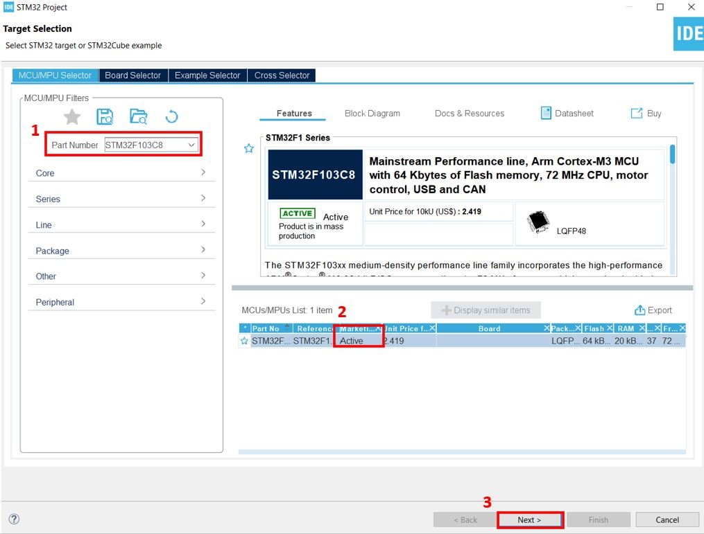
Then for the target selection, specify the STM32 Blue Pill board number. After that click on any column as shown in the picture below. Then click the ‘Next’ button.
Specify the name of your project then click ‘Finish’ to complete the setup of your project.
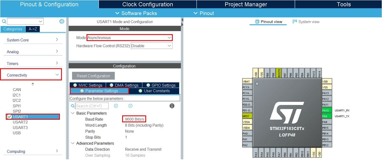
Now head over to Connectivity > USART1 and set the mode as ‘Asynchronous.’ Go to the parameter settings and set the baud rate to 9600 Bits/s.
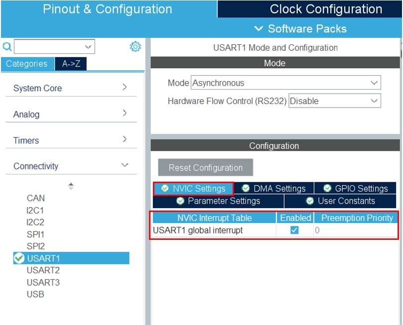
Then head over to NVIC Settings under configuration and enable the USART1 global interrupt. This will enable UART global interrupt and also enables it in nested vectored interrupt controller (NVIC). You can learn more about NVIC here:
Now go to System Core > RCC then select ‘Crystal/Ceramic Resonator’ in from the High Speed Clock feature.
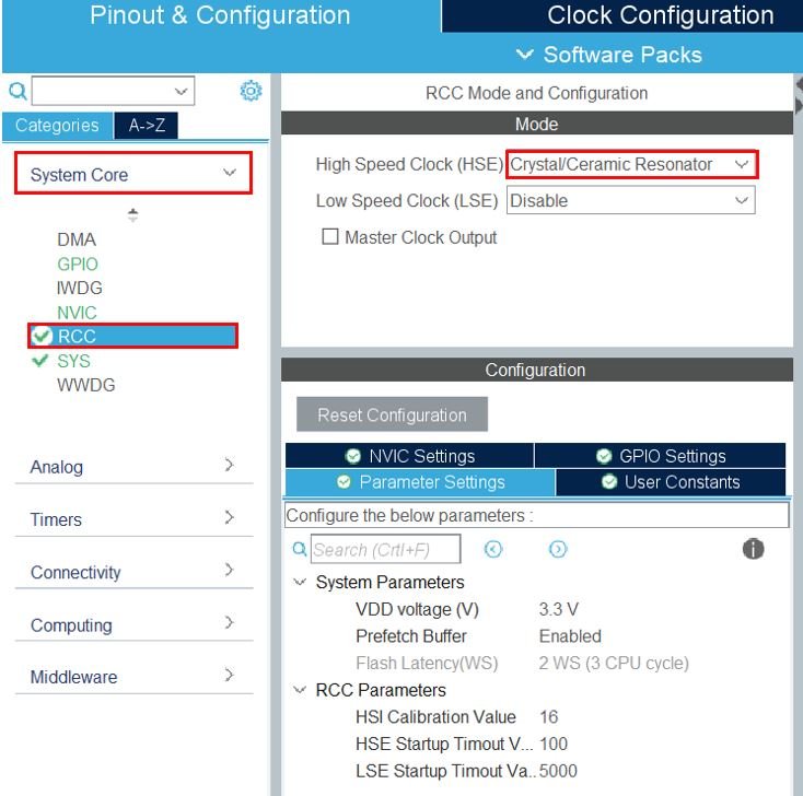
Now we have enabled the RCC external clock source.
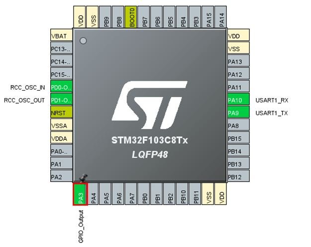
Set PA3 as GPIO_Output. This is the pin that we will use to connect the LED.
Clock Configuration
Next, go to the Clock Configuration found at the top. This will open the following window. Here we will select the clock frequency.
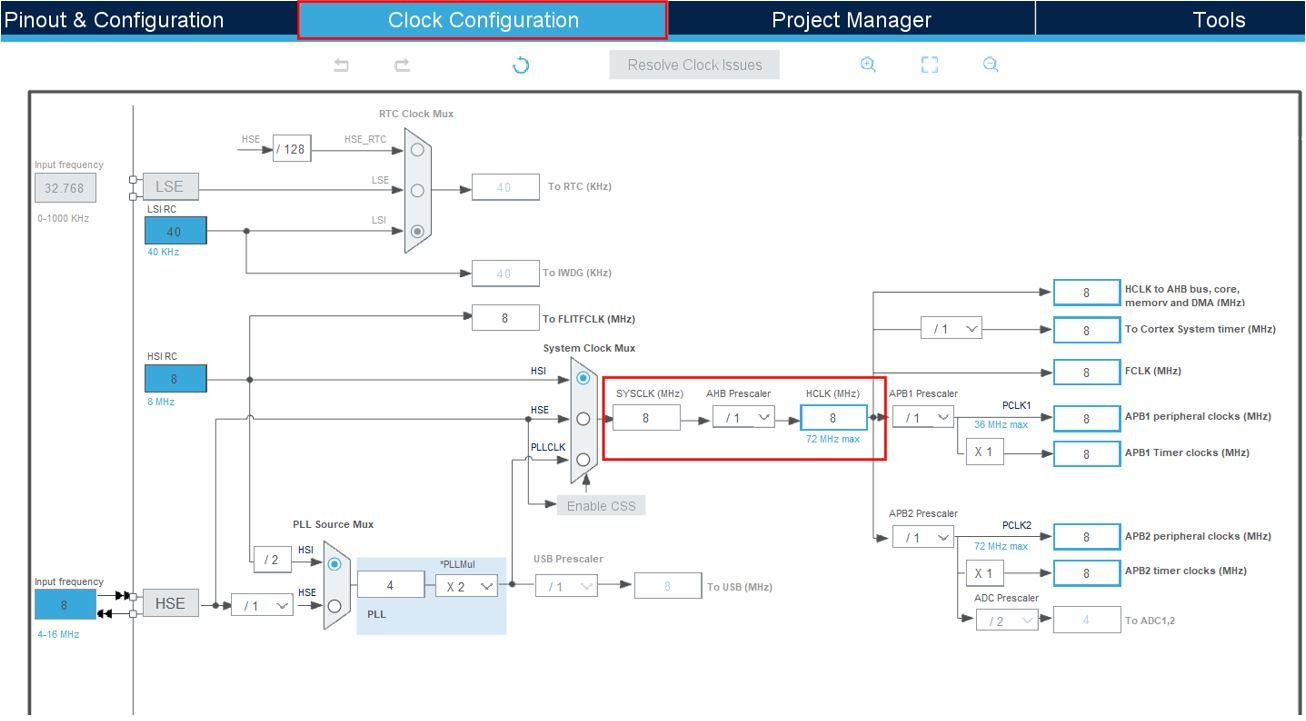
You can specify your system clock. We will set it as 72 MHz. These are the configurations we have set:

Now we will save our file. Press Ctrl + S. The following window will appear. Click ‘Yes.’ This will generate a template code for you.

Another window will appear that will ask if you want to open the perspective. Click ‘Yes.’

STM32 Blue Pill HC-05 UART Interrupt Code
We will use STM32 Blue Pill UART in interrupt mode to receive data from the android application via the UART1 pins of STM32 through the HC-05 Bluetooth module. We will control the STM32 Blue Pill GPIO pin with an LED connected to it. This will be done through the android application via the Bluetooth module. We will send ‘O’ or ‘X’ commands from our Serial Bluetooth Terminal application. Based on these commands, the LED will either turn ON or OFF.
Now let us look at our main.c file that was generated. Inside the main.c file, make sure the following code is part of your script by including the lines of code given below.
#include "main.h"

UART_HandleTypeDef huart1;
uint8_t rxData;

void SystemClock_Config(void);
static void MX_GPIO_Init(void);
static void MX_USART1_UART_Init(void);

int main(void)
{
  HAL_Init();
  SystemClock_Config();

  MX_GPIO_Init();
  MX_USART1_UART_Init();
  HAL_UART_Receive_IT(&huart1,&rxData,1);

  while (1)
  {

  }

}

void HAL_UART_RxCpltCallback(UART_HandleTypeDef *huart)
{
  if(huart->Instance==USART1)
  {
    if(rxData==79) // Ascii value of 'O' is 79
    {
    	HAL_GPIO_WritePin(GPIOA, GPIO_PIN_3, 1);
    }
    else if (rxData==88) // Ascii value of 'X' is 88
    {
    	HAL_GPIO_WritePin(GPIOA, GPIO_PIN_3, 0);
    }
    HAL_UART_Receive_IT(&huart1,&rxData,1); // Enabling interrupt receive again
  }
}
Working of the Code
First, create a receiving buffer called rxData outside the main() function. This will hold the data whenever STM32 will receive data via UART interrupt.
uint8_t rxData;UART Interrupt Call Back Function
The HAL_UART_RxCpltCallback() function is called when data reception is completed. This function is known as Rx Transfer completed callback. It takes in a single parameter ‘huart’ which is the pointer to the UART_HandleTypeDef structure containing the configuration parameter for the specified UART module. Inside this function, new data transmission and reception is initiated so that the continuity of the transmission/reception of data remains. This will ensure the data transfer occurs in a non-blocking mode.
One important point to note here is that we have specified the received buffer size is 1 byte. Therefore, this HAL_UART_RxCpltCallback function will be only triggered once Rx transfer has completely received 1 byte. But one can change it according to its requirement.
Inside this function we will add the logic to control the LED connected with PA3 of STM32 Blue Pill. When the received data is equal to 79 then we will set the state of the LED pin as HIGH using HAL_GPIO_WritePin(). This function sets or clears the selected data port bit by taking in the selected GPIO peripheral as the first parameter, GPIO port bit as the second parameter and the pin state as the third parameter. 79 is the ASCII value for O which the user will send over from the Bluetooth application. Similarly, if the received data is equal to 88 (ASCII for X) then we will set the state of the LED pin as LOW.
void HAL_UART_RxCpltCallback(UART_HandleTypeDef *huart)
{
  if(huart->Instance==USART1)
  {
    if(rxData==79) // Ascii value of 'O' is 79
    {
    	HAL_GPIO_WritePin(GPIOA, GPIO_PIN_3, 1);
    }
    else if (rxData==88) // Ascii value of 'X' is 88
    {
    	HAL_GPIO_WritePin(GPIOA, GPIO_PIN_3, 0);
    }
    HAL_UART_Receive_IT(&huart1,&rxData,1);
  }
}
HAL UART Data Receive Interrupt Function
HAL_UART_Receive_IT() function is responsible for receiving an amount of data in non-blocking mode. This function enables UART data reception in interrupt mode and defines size of data to be received.
HAL_StatusTypeDef HAL_UART_Receive_IT(UART_HandleTypeDef * 	huart,
 uint8_t * pData,
 uint16_t Size)
This function takes in three parameters.
- The first parameter is the pointer to the UART_HandleTypeDef structure containing the configuration parameters for the specified UART module. In our case, it is &huart1.
- The second parameter is the pointer to the data buffer which holds the received data. In our case it is &rxData.
- The third parameter is the size of data to be received. In our case it is 1.
HAL_UART_Receive_IT(&huart1,&rxData,1);main.c file
This is how a complete main.c file will be after modification.
#include "main.h"

UART_HandleTypeDef huart1;
uint8_t rxData;

void SystemClock_Config(void);
static void MX_GPIO_Init(void);
static void MX_USART1_UART_Init(void);

int main(void)
{
  HAL_Init();
  SystemClock_Config();

  MX_GPIO_Init();
  MX_USART1_UART_Init();
  HAL_UART_Receive_IT(&huart1,&rxData,1);

  while (1)
  {

  }

}

void HAL_UART_RxCpltCallback(UART_HandleTypeDef *huart)
{
  if(huart->Instance==USART1)
  {
    if(rxData==79) // Ascii value of 'O' is 79
    {
    	HAL_GPIO_WritePin(GPIOA, GPIO_PIN_3, 1);
    }
    else if (rxData==88) // Ascii value of 'X' is 88
    {
    	HAL_GPIO_WritePin(GPIOA, GPIO_PIN_3, 0);
    }
    HAL_UART_Receive_IT(&huart1,&rxData,1); // Enabling interrupt receive again
  }
}

/**
  * @brief System Clock Configuration
  * @retval None
  */
void SystemClock_Config(void)
{
  RCC_OscInitTypeDef RCC_OscInitStruct = {0};
  RCC_ClkInitTypeDef RCC_ClkInitStruct = {0};

  /** Initializes the RCC Oscillators according to the specified parameters
  * in the RCC_OscInitTypeDef structure.
  */
  RCC_OscInitStruct.OscillatorType = RCC_OSCILLATORTYPE_HSE;
  RCC_OscInitStruct.HSEState = RCC_HSE_ON;
  RCC_OscInitStruct.HSEPredivValue = RCC_HSE_PREDIV_DIV1;
  RCC_OscInitStruct.HSIState = RCC_HSI_ON;
  RCC_OscInitStruct.PLL.PLLState = RCC_PLL_ON;
  RCC_OscInitStruct.PLL.PLLSource = RCC_PLLSOURCE_HSE;
  RCC_OscInitStruct.PLL.PLLMUL = RCC_PLL_MUL9;
  if (HAL_RCC_OscConfig(&RCC_OscInitStruct) != HAL_OK)
  {
    Error_Handler();
  }
  /** Initializes the CPU, AHB and APB buses clocks
  */
  RCC_ClkInitStruct.ClockType = RCC_CLOCKTYPE_HCLK|RCC_CLOCKTYPE_SYSCLK
                              |RCC_CLOCKTYPE_PCLK1|RCC_CLOCKTYPE_PCLK2;
  RCC_ClkInitStruct.SYSCLKSource = RCC_SYSCLKSOURCE_PLLCLK;
  RCC_ClkInitStruct.AHBCLKDivider = RCC_SYSCLK_DIV1;
  RCC_ClkInitStruct.APB1CLKDivider = RCC_HCLK_DIV2;
  RCC_ClkInitStruct.APB2CLKDivider = RCC_HCLK_DIV1;

  if (HAL_RCC_ClockConfig(&RCC_ClkInitStruct, FLASH_LATENCY_2) != HAL_OK)
  {
    Error_Handler();
  }
}

/**
  * @brief USART1 Initialization Function
  * @param None
  * @retval None
  */
static void MX_USART1_UART_Init(void)
{

  /* USER CODE BEGIN USART1_Init 0 */

  /* USER CODE END USART1_Init 0 */

  /* USER CODE BEGIN USART1_Init 1 */

  /* USER CODE END USART1_Init 1 */
  huart1.Instance = USART1;
  huart1.Init.BaudRate = 9600;
  huart1.Init.WordLength = UART_WORDLENGTH_8B;
  huart1.Init.StopBits = UART_STOPBITS_1;
  huart1.Init.Parity = UART_PARITY_NONE;
  huart1.Init.Mode = UART_MODE_TX_RX;
  huart1.Init.HwFlowCtl = UART_HWCONTROL_NONE;
  huart1.Init.OverSampling = UART_OVERSAMPLING_16;
  if (HAL_UART_Init(&huart1) != HAL_OK)
  {
    Error_Handler();
  }
  /* USER CODE BEGIN USART1_Init 2 */

  /* USER CODE END USART1_Init 2 */

}

/**
  * @brief GPIO Initialization Function
  * @param None
  * @retval None
  */
static void MX_GPIO_Init(void)
{
  GPIO_InitTypeDef GPIO_InitStruct = {0};

  /* GPIO Ports Clock Enable */
  __HAL_RCC_GPIOD_CLK_ENABLE();
  __HAL_RCC_GPIOA_CLK_ENABLE();

  /*Configure GPIO pin Output Level */
  HAL_GPIO_WritePin(GPIOA, GPIO_PIN_3, GPIO_PIN_RESET);

  /*Configure GPIO pin : PA3 */
  GPIO_InitStruct.Pin = GPIO_PIN_3;
  GPIO_InitStruct.Mode = GPIO_MODE_OUTPUT_PP;
  GPIO_InitStruct.Pull = GPIO_NOPULL;
  GPIO_InitStruct.Speed = GPIO_SPEED_FREQ_LOW;
  HAL_GPIO_Init(GPIOA, &GPIO_InitStruct);

}

/* USER CODE BEGIN 4 */

/* USER CODE END 4 */

/**
  * @brief  This function is executed in case of error occurrence.
  * @retval None
  */
void Error_Handler(void)
{
  /* USER CODE BEGIN Error_Handler_Debug */
  /* User can add his own implementation to report the HAL error return state */
  __disable_irq();
  while (1)
  {
  }
  /* USER CODE END Error_Handler_Debug */
}

#ifdef  USE_FULL_ASSERT
/**
  * @brief  Reports the name of the source file and the source line number
  *         where the assert_param error has occurred.
  * @param  file: pointer to the source file name
  * @param  line: assert_param error line source number
  * @retval None
  */
void assert_failed(uint8_t *file, uint32_t line)
{
  /* USER CODE BEGIN 6 */
  /* User can add his own implementation to report the file name and line number,
     ex: printf("Wrong parameters value: file %s on line %d\r\n", file, line) */
  /* USER CODE END 6 */
}
#endif /* USE_FULL_ASSERT */
Save the main.c file after modifying it. Now we are ready to build our project.
Building the Project
To build our project press Ctrl + B or go to Project > Build All.
Your project will start building. After a few moments, your project will be successfully built if there are no errors.
Connecting ST-Link Programmer with STM32
Now as we have successfully built our project let us move ahead and upload the code to our STM32 board. To do that, first we will have to connect our Blue Pill STM32 with a ST-Link programmer. We will be using ST-Link V2.

This will provide an interface between our computer and our STM32 board. It consists of 10 pins. We will be using pin2 SWDIO, pin6 SWCLK, pin4 GND, and pin8 3.3V to connect with our STM32 board. The SWDIO is the data input/output pin and the SWCLK is the clock pin. Follow the pin configuration given on the ST-LINK V2 to identify each pin.
Follow the table below to connect both devices correctly.
| STM32 | ST-LINK V2 |
| VCC 3.3V pin | pin8 3.3V |
| SWDIO pin | pin2 SWDIO |
| SWCLK pin | pin6 SWCLK |
| GND pin | pin4 GND |

Additionally, move the BOOT jumper to the right to enable the microcontroller to go into programming mode.

Hardware Setup for STM32 Blue Pill HC-05 Bluetooth LED Control
For this project we will require the following components:
- STM32 Blue Pill
- HC-05 Bluetooth Module
- 5mm LED
- 220-ohm resistor
- Connecting Wires
- Breadboard
Connect the components as shown in the schematic diagram below:
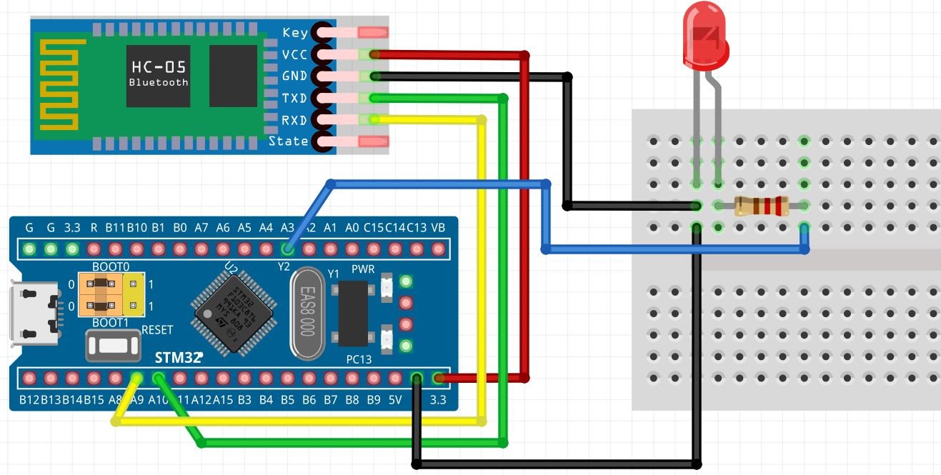
Follow the schematic diagram below to connect all the devices together. We will power the HC-05 module with 3.3V pin of STM32. The RX and TX pins of the HC-05 module will be connected with the UART1 TX and RX pins of the STM32 board respectively. PA10 is UART1_RX pin and PA9 is UART1_TX pin. We will use PA3 to connect with the anode pin of LED through a 220 ohm current limiting resistor, and the cathode pin with the common ground. Moreover, all the grounds will be in common.
Demonstration
- Now connect your ST-LINK V2 with your computer via the USB port. Both devices will power ON.
- Next press the RUN button in the IDE. The ‘Edit configuration’ window will open up. Click ‘OK’.
- After a few moments, the code will be successfully sent to the STM32 board. Otherwise, press the RESET button on your STM32 board.
- Now to bring the Blue pill back to normal mode make sure you bring the BOOT jumper back at its place.
Setting up Android App
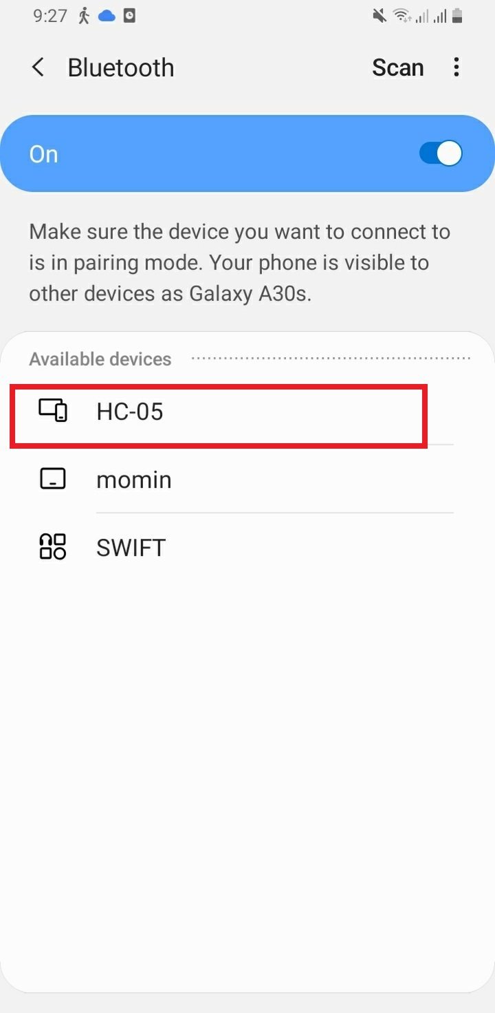
In your smartphone settings, enable Bluetooth and scan for available Bluetooth devices. You will see the HC-05 device in your scanned list. The default name for this Bluetooth device is “HC-05” and the default pin code is either “0000” or “1234”.
We will use an android smartphone to connect with our Raspberry Pi Pico. To do that you will have to perform a series of steps.
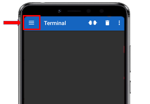
After you have installed the ‘Serial Bluetooth Terminal app, open it. On the top left corner of the screen, you will find three horizontal bars. Tap it.
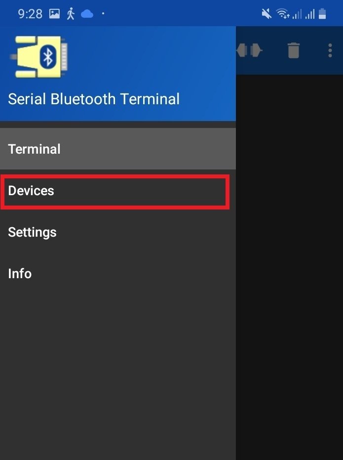
Now, tap on the Devices tab.
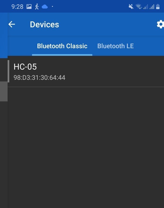
In the ‘available devices’ section, select ‘HC-05’
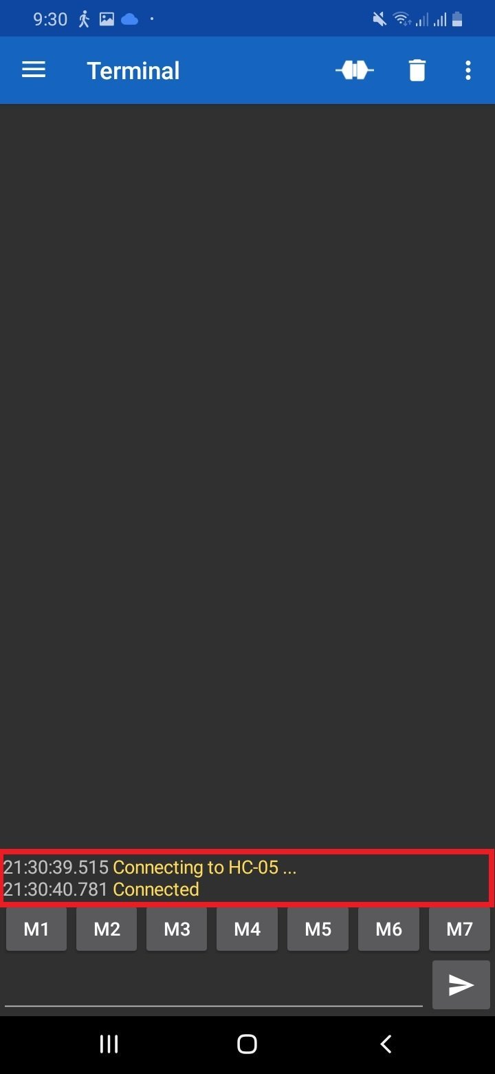
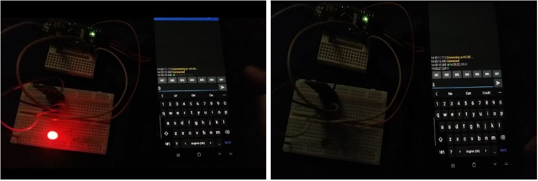
After you have selected the HC-05 module then tap the ‘link’ icon at the top of the screen. At first, you will get the message: ‘Connecting to HC-05.’ After a successful connection, you will get the message: ‘Connected.’
After you have selected the HC-05 module then tap the ‘link’ icon at the top of the screen. At first, you will get the message: ‘Connecting to HC-05.’ After a successful connection, you will get the message: ‘Connected.’
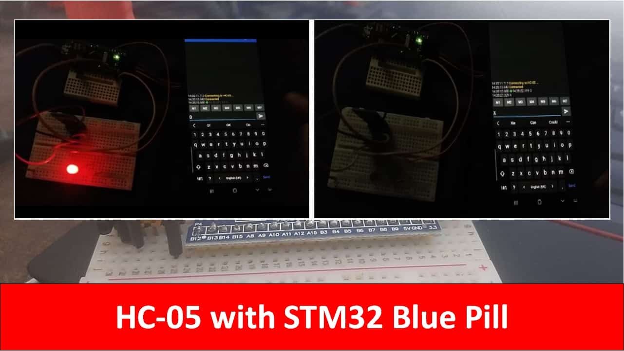
Now type ‘O’ and click on the send button. You will see the LED will turn ON. Similarly, when you send ‘X’ the LED turns OFF.
Watch the video demonstration below:
You may also like to read:
- STM32 Blue Pill SPI Communication with Master Slave Example
- STM32 Blue Pill Timer in PWM Mode with LED Dimmer Example
- STM32 Blue Pill ADC with Polling, Interrupt and DMA
- STM32 Blue Pill UART Interrupt with CubeIDE and HAL Libraries
Other HC-05 Bluetooth module related tutorials:
- HC-05 Bluetooth Interfacing with Raspberry Pi Pico – Control Outputs
- HC-05 Bluetooth Interfacing with ESP8266 NodeMCU – Control GPIO Pins
- HC-05 Bluetooth Interfacing with TM4C123G Tiva C Launchpad – Keil uvision
- Arduino LED Slider Brightness Control Android App with MIT App Inventor
- Arduino Send Messages from Android to LCD with MIT App Inventor
- Arduino Send Sensor Readings to Android app with MIT App Inventor
Thanks alot.. it helped e so much God bless you