BeagleBone Black is a small package of a microprocessor and memory which helps to operate the other embedded system through a Linux operating system. It is a system on chip SoC. It is a small packed of everything found on a computer or a laptop. The BeagleBone black is just like the simple BeagleBone but it is faster and has some extra features which make it preferable. Most of the engineers and developers like to use it as a server and hub for small networks. It is widely used in automation, IoT and robotic at the development level.
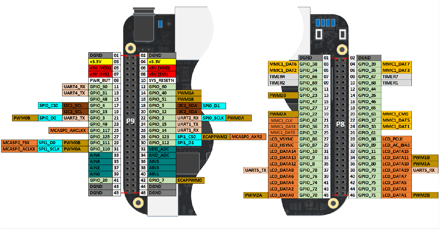
Pin Configuration Diagram BeagleBone Black
This section explains pinout diagram. We will learn about the functionality of all pins of BB. This BB consists of 1GHz, AM335x with ARM Cortex-A8 processor.
BeagleBone Balck Pinout Details
Power Pin BeagleBone Black
BeagleBone Black has two expansion headers P8 and P9, each header gives the 46 pins which can give 3.3V I/O signal. In the case of 5V on the pin, the board will be damaged.
Power Input: BeagleBone Black has two power inputs, one is through a DC power Jack input port and the second one is USB. Both ports have different power input ratings.
Power output: Beagle Bone has three power output pins; these pins can be used to give powers to external devices. 1. The first pin gives 3Volts and its power comes directly from LDO (Low Dropout) and it can be used for maximum 250mA current rating devices. In case of an increase in ampere external power device is recommended to use.
- The second power port gives 5 volts output and it comes directly from the DC Jack power supply pin. There won’t be any power on this pin when the device will be operated with a USB power pin. The current on this pin will be dependent on the DC power input but it will be limited to 1000mA
- The third power port uses a regulator and it comes from both USB and DC power. The voltage on this pin will be 5 volts but the current will depend on the power input.
All these pins are multiple in numbers and all of them are given below:
- In P9
- +3.3V – Pin3, Pin4
- +5V (VDD) – Pin5, Pin6
- +5V (SYS) – Pin7, Pin8
Ground: Every two devices need a common ground to operate and BeagleBone Black has multiple of them. All these pins are connected internally with each other and all the other peripherals. The list of all ground pins in BeagleBone Black are:
- In P8:
- DGND – Pin1, Pin2, Pin43, Pin44, Pin45, Pin46
- In P9:
- DGND – Pin 1, 2
Power Button: The power button is a special kind of feature within the BeagleBone Black. It allows to shut down the device orderly through an external pulse by saving all data. Power Button is only one and it is in the expansion header P9:
- PWR_BUT – Pin9
Reset Button: The device has an external reset button that restarts the device safely. The reset button is in P9 Header and its pin is given below:
- SYS_RESETN – Pin10
GPIO Pins BB
Digital Input/ Output: There are almost 69 I/O pins the device but the rest of them can also be used for other predefined functions. Those I/O pins have 3.3Volts on all the pins. In BeagleBone Black all I/O pins are given below:
- In P8 header:
- GPIO_30 – Pin11
- GPIO_60 – Pin12
- GPIO_31 – Pin 13
- GPIO_40 – Pin 14
- GPIO_48 – Pin 15
- GPIO_51 – Pin 16
- GPIO_4 – Pin17
- GPIO_5 – Pin18
- GPIO_13 – Pin19
- GPIO_12 – Pin20
- GPIO_3 – Pin21
- GPIO_2 – Pin22
- GPIO_49 – Pin23
- GPIO_15 – Pin24
- GPIO_117 – Pin25
- GPIO_14 – Pin26
- GPIO_125 – Pin27
- GPIO_123 – Pin28
- GPIO_111 – Pin29
- GPIO_112 – Pin30
- GPIO_110 – Pin31
- GPIO_20 – Pin41
- GPIO_7 – Pin42
- In P9 header:
- GPIO_38 – Pin3
- GPIO_39 – Pin4
- GPIO_34 – Pin5
- GPIO_35 – Pin6
- GPIO_66 – Pin7
- GPIO_67 – Pin8
- GPIO_69 – Pin9
- GPIO_68 – Pin10
- GPIO_45 – Pin11
- GPIO_44 – Pin12
- GPIO_23 – Pin13
- GPIO_26 – Pin14
- GPIO_47 – Pin15
- GPIO_46 – Pin16
- GPIO_27 – Pin17
- GPIO_65 – Pin18
- GPIO_22 – Pin19
- GPIO_63 – Pin20
- GPIO_62 – Pin21
- GPIO_37 – Pin22
- GPIO_36 – Pin23
- GPIO_33 – Pin24
- GPIO_32 – Pin25
- GPIO_61 – Pin26
- GPIO_86 – Pin27
- GPIO_88 – Pin28
- GPIO_87 – Pin29
- GPIO_10 – Pin31
- GPIO_11 – Pin32
- GPIO_9 – Pin33
- GPIO_81 – Pin34
- GPIO_8 – Pin35
- GPIO_80 – Pin36
- GPIO_78 – Pin37
- GPIO_79 – Pin38
- GPIO_76 – Pin39
- GPIO_77 – Pin40
- GPIO_74 – Pin41
- GPIO_75 – Pin42
- GPIO_72 – Pin43
- GPIO_73 – Pin44
- GPIO_70 – Pin45
- GPIO_71 – Pin46
BB UART Communication Pins
It is one of the most popular serial communication for most of the systems and devices. In this communication, sperate pins are used for transmitting and receiving data. In BeagleBone Black there are multiple UART communication systems, all of them are given below:
- In P8:
- UART5_TX – Pin37
- UART_RX – Pin38
- In P9:
- UART1_TX – Pin24
- UART1_RX – Pin26
- UART2_TX – Pin21
- UART2_RX – Pin22
- UART4_TX – Pin11
- UART4_RX – Pin13
SPI Communication Channel Pins
There are two SPI communication pins in BeagleBone Black. Both of these SPI also have separate slave select. Due to multiple slave select, each device could be used to communicate with two different kinds of SPI protocol devices. Both SPI communication pins are in Expansion Header P9:
- SPI0_CS0 – Pin17
- SPI0_D0 – Pin21
- SPI0_D1 – Pin18
- SPI0_SCLK – Pin22
- SPI1_CS0 – Pin28
- SPI1_D0 – Pin29
- SPI1_D1 – Pin30
- SPI1_SCLK – Pin31
I2C Communication Channels BeagleBone Black
There is another serial communication system known as I2C, which is by some sensors and servos. In BeagleBone there are two I2C communications pairs, and all of them are in P9 Expansion Header:
- I2C1_SCL – Pin17
- I2C1_SDA – Pin18
- I2C2_SCL – Pin19
- I2C2_SDA – Pin20
PWM Channel Pins
BeagleBone Black can generate the desired output square pulse to control the motors or any other operate able devices. It has multiple PWM pins that use internal timers and Prescaler to generate the output signal. All PWM pins are given below:
- In P8:
- PWM0A – Pin22
- PWM0B – Pin21
- PWM0A – Pin31
- PWM0B – Pin29
- PWM1A – Pin14
- PWM1B – Pin16
- ECAPPWM0 – Pin42
- ECAPPWM2 – Pin28
- In P9:
- PWM1A – Pin36
- PWM1B – Pin34
- PWM2A – Pin45
- PWM2B – Pin46
- PWM2A – Pin19
- PWM2B – Pin13
ECAP-PWM: Those pins are for PWM signal generator but they can also be programmed for the PWM input signal. PWM can use to calculate the external device frequency and duty cycle. ECAPPWM pins are limited in number in BeagleBone Black and all of them are listed below:
- In P9:
- ECAPPWM0 – Pin42
- ECAPPWM2 – Pin28
MCASP Pins
It is a port used for multi-channel serial applications. It uses the sperate clock, data and frame sync pin. In Beagle Bone the MCASP pins are in P9 Header which is given below:
- MCASP0_FSX (Frame Sync) – Pin29
- MCASP0_ACLKX (Clock Sync) – Pin25
- MCASP0_AHCLKX (Data Out) – Pin31
- MCASP0_AXR2 (Data In) – Pin28
MMC Support Pins BeagleBone Black
It stands for a multimedia controller. In BeagleBone Black there is an embedded 2GB MMC that allows the device to boot from the built-in eMMC instead of an SD card. The MMC1 is a default boot mode directly connected to processor port but in case of SD card, the default mode will not be used because eMMC is 8-bit and allow specific pins to perform. The third MMC which is called MMC2 will be used by other modules, only MMC1 has external pins to operate. All MMC1 pins are in Header P8:
- MMC1_CMD – Pin20
- MMC1_CLK – Pin21
- MMC1_DAT0 – Pin25
- MMC1_DAT1 – Pin24
- MMC1_DAT2 – Pin5
- MMC1_DAT3 – Pin6
- MMC1_DAT4 – Pin23
- MMC1_DAT5 – Pin22
- MMC1_DAT6 – Pin3
- MMC1_DAT7 – Pin4
BB HDMI LCD Interface Pins
Beagle Bone can be used to drive the LCD through HDMI. It has some pins which are used for HDMI framer but those pins are used for performing some other function. So in case of using these pins for other functions, the framer won’t operate because all these pins are for input signals. All these pins are in Expansion Header P8 which are listed below:
- LCD_VSYNC – Pin27
- LCD_PCLK – Pin28
- LCD_HSYNC – Pin29
- LCD_AC_BIAS – Pin30
- LCD_DATA14 – Pin31
- LCD_DATA15 – Pin32
- LCD_DATA13 – Pin33
- LCD_DATA11 – Pin34
- LCD_DATA12 – Pin35
- LCD_DATA10 – Pin36
- LCD_DATA8 – Pin37
- LCD_DATA9 – Pin38
- LCD_DATA6 – Pin39
- LCD_DATA7 – Pin40
- LCD_DATA4 – Pin41
- LCD_DATA5 – Pin42
- LCD_DATA2 – Pin43
- LCD_DATA3 – Pin44
- LCD_DATA0 – Pin45
- LCD_DATA1 – Pin46
Analog to Digital Converter Channels
In BeagleBone analog signal can be converted directly to the Digital Signal. It has a total of 7 A/D channels and all of them use a single 12-bit ADC channel which needs to be activated first by give 1.8V power through ADC power pins. All ADC channels and power pins are in expansion header P9 which are given below:
- AIN0 – Pin39
- AIN1 – Pin40
- AIN2 – Pin37
- AIN3 – Pin38
- AIN4 – Pin33
- AIN5 – Pin36
- AIN6 – Pin35
- VDD_ADC – Pin32
- GND_ADC – Pin34
BeagleBone Timers Modules Pins
Timers have become the basic requirement of most of the external devices. BeagleBone Blacks provide the four internal timers which are being used according to the external pulse input pins. All these pins are in P8, which are given below:
- TIMER1 – Pin10
- TIMER2 – Pin9
- TIMER4 – Pin7
- TIMER7 – Pin8
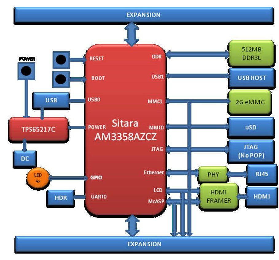
BeagleBone Black Block Diagram
The block diagram of the BeagleBone Black is given below:
Applications
- It is used in small network projects by developers for testing and designing.
- In most of the IoT projects at commercial devices comes with BeagleBone as a Server.
- BeagleBone Black is used as a single control unit for most of the industrial devices.
BeagleBone Black main Features
| FEATURES & SPECIFICATIONS | |
|---|---|
| Graphics Engine | SGX530 3D, 20M Polygons/S |
| CPU Frequency | 1GHz, AM335x with ARM Cortex-A8 processor |
| Operating Voltage Range | 5V with 210-460mA |
| GPIO PORTS | 69 I/O Pins (but other can be used) |
| LAN | Available |
| SD Card | Available |
| HDMI | Available |
| WIFI | Not Available |
| PWR Exp Header | Not Available |
| Power Source | DC Power Jack, mini USB Port |
| Expansion Connectors | MCASP, SPI, I2C, LCD, MMC, GPMC, USART, Power Button, XDMA Interrupt, CAN, EHRPWM, PWM, ADC |
| SRAM | 512MB (DDR3L – 800MHz) |
| Debug | JTAG and Serial Header |
| FLASH (Program Memory) | 4GB, 8-bit eMMC |
| EEPROM | 512 bytes |
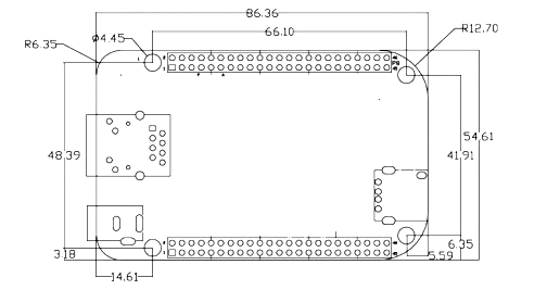
2D DIAGRAM for PCB
nice post, keep it up