The STM32F4 Discovery board is small devices based on STMF407 ARM microcontroller, which is a high-performance microcontroller. This board allows users to develop and design applications. It has multiple modules within itself which allows the user to communicate and design the interface of different kinds without relying on any third device. The board has all the modern system modules peripherals like DAC, ADC, audio port, UART, etc which makes it one of the best-developing devices. The device may be for developing modern applications but some protocols will need to be followed to use the device, like the compiler, voltage potential, etc. In this tutorial, we will discuss swd pinout, pin configuration, pin description, features, and examples.
Recommended Components
The following parts are used in this article, along with a generic electronics kit that is handy for building and testing the circuit.
| Component | How it’s used | Buy on Amazon |
|---|---|---|
| STM32F4 Discovery board | The STM32F4 Discovery (STM32F407) board this article covers. | Check Price |
| Electronic component assortment kit (1390 pcs) | A handy assortment of resistors, capacitors, LEDs, diodes and transistors for building circuits. | Check Price |
| Digital multimeter (AstroAI) | Measures voltage, current, resistance and checks continuity while you build and debug. | Check Price |
| Breadboard | Solderless base for prototyping the circuit. | Check Price |
| Jumper Wires | Make the connections on the breadboard. | Check Price |
As an Amazon Associate we earn from qualifying purchases. Prices and availability are accurate as of the date/time indicated and are subject to change.
STM32F4 Discovery Pinout Diagram
We list the pinout layout and pins description in this section. Pin configuration diagram is here:
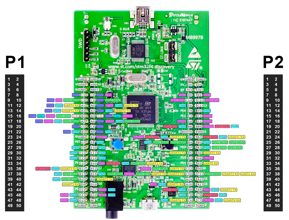
The STM32F4 has two male headers P1 and P2, both headers are connected to port A, C, D, E & H which will be used for further functions.
Power supply pins
This board provides onboard power pins to give power to external sensors or circuits.
Power Input: The STM32F4 has multiple power pins are all pins can be used any 5-V power supply to power up the device. The power-up the whole device only pins can be used, power input through USB won’t be able to activate all modules of the device. All Power input pin is given below:
In P1 Header:
- VDD – Pin3, Pin4
In P2 Header:
- 5V – Pin3, Pin4
- VDD – Pin22
Power Output: Different power levels have always been a requirement for every device, and to fulfill the requirement there is an internal regulator within the STM32F4. It has two power pin one is 5Volt and the second one is 3V3. 5V pin is directly connected to the power input and 3V3 is connected through the regulator. Both pins are in header P2:
- 5V – Pin3, Pin4
- 3V3 – Pin5, Pin6, GPIO15, GPIO16
Ground: In the case of multiple external devices the ground becomes the basic requirement for each device to make the common ground. This device has multiple ground pins in both headers which can be used individually. All of them are connected internally and they are listed below:
In P1 Header:
- GND – Pin1, Pin2, Pin5, Pin23, Pin49, Pin50
In P2 Header:
- GND – Pin1, Pin2, Pin49, Pin50
STM32F4 Oscillator Pins
STM32F4 may be larger and smarter but it doesn’t have any internal crystal for clock pulse. It has four external clock pulse pins two they are used for 32KHz crystal and the other two are used for High-frequency crystal. The crystal can be used up to 50MHz on that pin but after 25MHz it becomes tricky to handle the crystal. These crystal pins can be used as GPIO, so it should be instructed within the program about the use of an oscillator. Both oscillators can’t be used at the same time and both are in the same header P2.
- OSC (IN) – GPIO7
- OSC (OUT) – GPIO
- OSC RTC (IN) – GPIO9
- OSC RTC (OUT) – GPIO10
STM32F4 Discovery Board GPIO Pins
These are a total of six ports (A, B, C, D, E, H) in the device and all of them come with an internal pull-up resistor and can be used for input/output function. Those pins also support some other functions and it can be controlled using programming. All I/O pins are given below:
In P1 Header:
- GPIO7 – GPIO22
- GPIO24 – GPIO47
In P2 Header:
- GPIO7 – GPIO21
- GPIO23 – GPIO48
STM32F4 Discovery Board USART Communication Pins
There is multiple serial communication within the STM32F4 and USART is one of them due to its popularity and easiness. The USART uses only two wires and the rest of the protocol depends on the controllers. In STM32F4 all USART communications are the same but each one of them should be initialized within the program to avoid any kind of conflict. All USART pins of STM32F4 are given below:
In P1 Header:
- USART2 TX – GPIO14
- USART2 RX – GPIO13
- USART3 TX – GPIO34, GPIO40
- USART3 RX – GPIO37, GPIO42
- USART4 TX – GPIO12
- USART4 RX – GPIO11
In P2 Header:
- USART1 TX – GPIO23, GPIO44
- USART1 RX – GPIO24, GPIO41
- USART2 TX – GPIO29
- USART2 RX – GPIO30
- USART3 TX – GPIO37
- USART3 RX – GPIO38
- USART4 TX – GPIO37
- USART4 RX – GPIO38
- USART5 TX – GPIO35
- USART5 RX – GPIO34
- USART6 TX – GPIO47
- USART6 RX – GPIO48
SPI Communication Channels
Serial Peripheral Interface is also becoming popular due to its working method. It handles multiple SPI devices of the same kind efficiently. In STM32F4 there are multiple GPIO pins that can be used as SPI pins through programming. All these pins are given below:
In Header P1:
- SPI2 MOSI – GPIO9
- SPI2 MISO – GPIO10
- SPI1 SCK – GPIO15
- SPI1 MOSI – GPIO17
- SPI1 MISO – GPIO18
- SPI2 SCK – GPIO34
- SPI2 SCK – GPIO37
- SPI2 MISO – GPIO38
- SPI2 MOSI – GPIO39
In Header P2:
- SPI1 MISO – GPIO25
- SPI3 MISO – GPIO25
- SPI1 MOSI – GPIO26
- SPI3MOSI – GPIO26
- SPI3 SCK – GPIO28
- SPI1 SCK – GPIO28
- SPI3 MOSI – GPIO35
- SPI3 SCK – GPIO37
- SPI3 MISO – GPIO38
STM32F4 Discovery Board I2C Channels
There are multiple modules and motors which only follow the I2C communication due to their internal structure. In that case, the device can only communicate with them with I2C protocol and multiple GPIO Pins support this communication only through programming. All these pins are:
In P1 Header:
- I2C2 SCL – GPIO34
- I2C2 SDA – GPIO35
In P2 Header:
- I2C1 SCL – GPIO19
- I2C1 SDA – GPIO20
- I2C1 SCL – GPIO23
- I2C1 SDA – GPIO24
- I2C3 SCL – GPIO43
- I2C3 SDA – GPIO46
STM32F4 Discovery Board ADC
There are multiple analogs to digital converter in the STM32F4. All these converters can be used individually with any TTL or ST output device to convert the analog data to digital. And ADC channels only exist in header P1.
- GPIO7 – GPIO22
DAC Pins
The device also supports two digitals to analog converting channels which convert any digital input to its voltage level. All DAC pins in STM32F4 are in header P1:
- GPIO15
- GPIO16
STM32F4 Audio Input Channel Pins
Audio communication is increasing now a day and STM32F4 supports multiple audio pins. In these audio pins, some of them have an internal D speaker Driver. These audio pins only use to receive the audio from the device, they can’t be used for audio in. All audio pins are given below:
In P1 Header:
- GPIO15
- GPIO16
- GPI38
In P2 Header only simple Audio exist:
- GPIO20
- GPIO32
- GPIO35
- GPIO47
MIC: To send the audio signal to the device a mic pin can be used which allows the user to send the audio by interfacing the mic with the STM32F4. There is only one mic pin within the whole device and it is given below:
- GPIO9
Pulse Width Modulation Channels
STM32F4 can also generate a PWM signal. In this device, the number of PWM signals is much greater than most of the devices. All PWM pin can be used individually for output signal and all of them are given below:
In Header P1:
- GPIO11 – GPIO18
- GPIO21, GPIO22
- GPIO26 – GPIO32
- GPIO34-GPIO35
- GPIO37 – GPIO39
- GPIO44 – GPIO47
In header P2:
- GPIO11
- GPIO14
- GPIO19
- GPIO20
- GPIO23 – GPIO26
- GPIO28
- GPIO41
- GPIO43 – GPIO48
MEMS Sensor Interface Channels
The devices support the electro-mechanical sensors interfacing with itself. It can use the MEMS pins to connect those devices with itself. All those pins are listed below:
In P1 Header:
- GPIO15
- GPIO17
- GPIO18
In P2 Header:
- GPIO16
- GPIO17
- GPIO18
RESET: STM32F4 also has a reset pin in header P1 which can be used externally to reset the device by giving a pulse:
- NRST – Pin6
BOOT: In STM32F4 there are two different boot pins, Boot0 and Boot1. Both pins are used to select the boot space. All these pins required different combinations to select different memory. All these pins are given below
| BOOT0 – GPIO21 (P2) | BOOT1 – GPIO24 (P1) | MEMORY |
| X | 0 | Main Flash Memory |
| 0 | 1 | System Memory |
| 1 | 1 | Embedded SRAM |
These all pins we discussed are the most used protocols, but in STM32F4 there are a bunch of other functions that can be generated through all ports just by using different programs. For all these alternative functions, you can go through a datasheet.
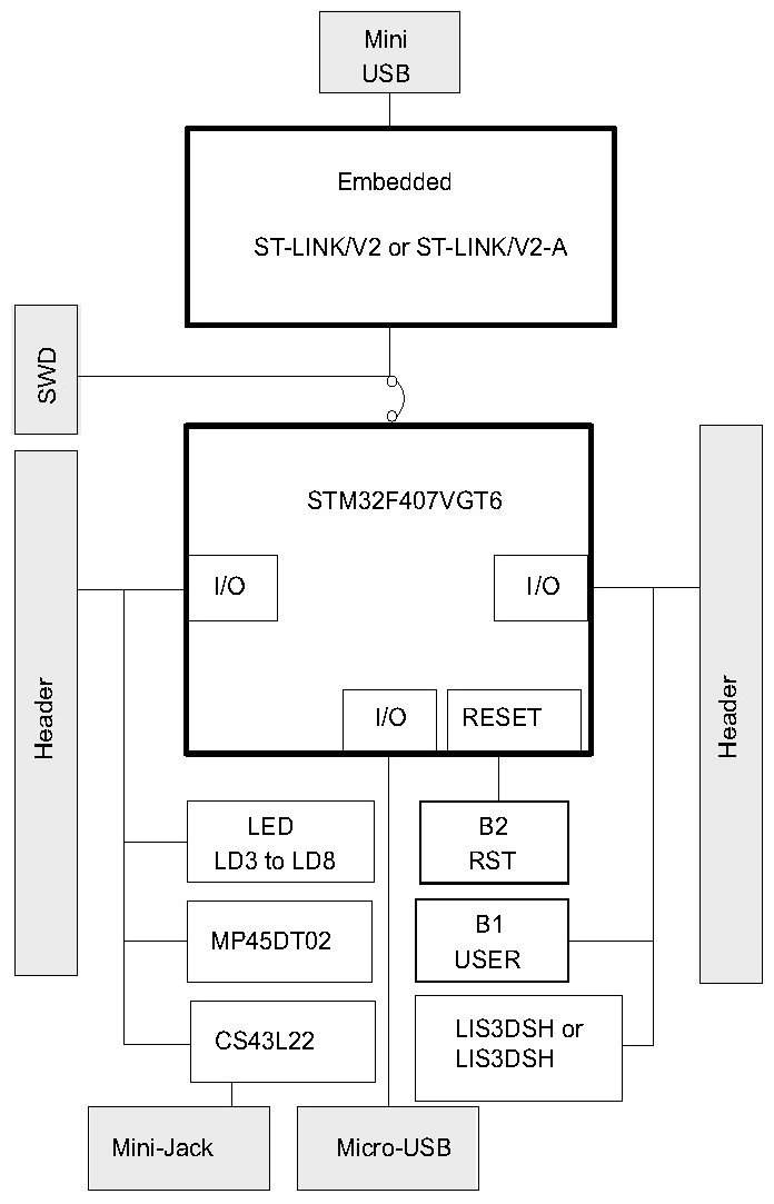
STM32F4 Discovery Board Block Diagram
STM32f4 Discovery Board Features
| FEATURES & SPECIFICATIONS | |
|---|---|
| CPU | ARM 32-bit Cortex @ 180MHz |
| RAM | 192KB |
| FLASH | 1MB |
| Operating Voltage Range | 5V |
| Debug Port | Available |
| Audio Port | Available |
| OTG USB | Available |
| LAN | Not Available |
| WIFI | Not Available |
| Bluetooth | Not Available |
| SD Card Slot | Not Available |
STM32F4 Board Peripherals
The STM32F4 has multiple internal peripherals which are given below:
Audio Port: In STM32F4 there are audio pins within the GPIO pins but it also has an external audio port, which can be used to plug the external audio pin for any audio in or out.
USB: The USB port on the board is OTG USB type and it can only be used to program the controller. There are no ways the controller can get the power the USB, but the voltage on the USB port should not exceed more than 5V otherwise it could harm the board.
Current Consumption: There is a current consumption pin on the board which uses a jumper, but it can be removed to measure the current consumption of the controller by attaching an ammeter.
Accelerometer: The 3-line accelerometer is attached on the board which can be used to measure any kind of acceleration of force implement on the board. It helps to devices when the device is being used with the robot or other motion-based projects. It doesn’t depend on any external device or interface; only internal programming will be able to make them functional.
Debug Port: There is a JTAG-SWD port on the device which helps the company and developers to debug the device. These pins can be used to program them controller directly by using specific external controllers.
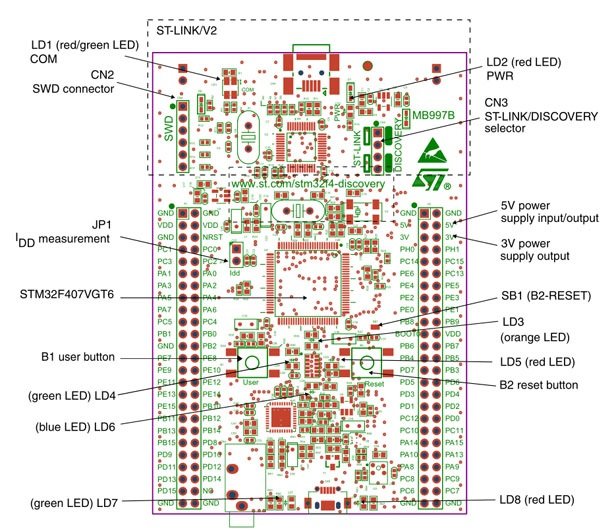
Button and Indicators: The STM32F4 has multiple colors of led which indicates multiple functions and buttons with different functions on the board. All of them and their function can be view in the following diagram:
STM32F4 Discovery Board Programming
Multiple IDEs can be used for programming the STM32F401. Some include:
- Atollic
- Keil
- STM32 Cube MX
- LabVIEW
- MATLAB
Programming Examples
To learn embedded systems programming, we always start with GPIO Ports programming, You can check these programming examples of this discovery board.
Applications
- The device is being widely used for developing projects like robots or cars
- Developers also like to use the SMT32F4 in industrial projects due to its multi-functional.
- It is used mostly in GPS logger and voice communication projects
I am not finding PWM complementary output pins contained Timer 1 ad Timer 8