Raspberry Pi is a small-sized computer used Linux operating system. It is mini size computer used mostly to run larger and smart programs to achieve output quickly. Raspberry Pi 4 B+ (RP4) is the lasted model developed by the company, which has all the required latest wired and wireless communications systems used in most of the smart projects. A single Raspberry Pi 4 comes to a Quad-Core processor but it has three different versions which give three different sizes of RAM. Pi 4 uses mini HDMI and it also has two ports for two 4K displays.

Raspberry Pi Pin Configuration
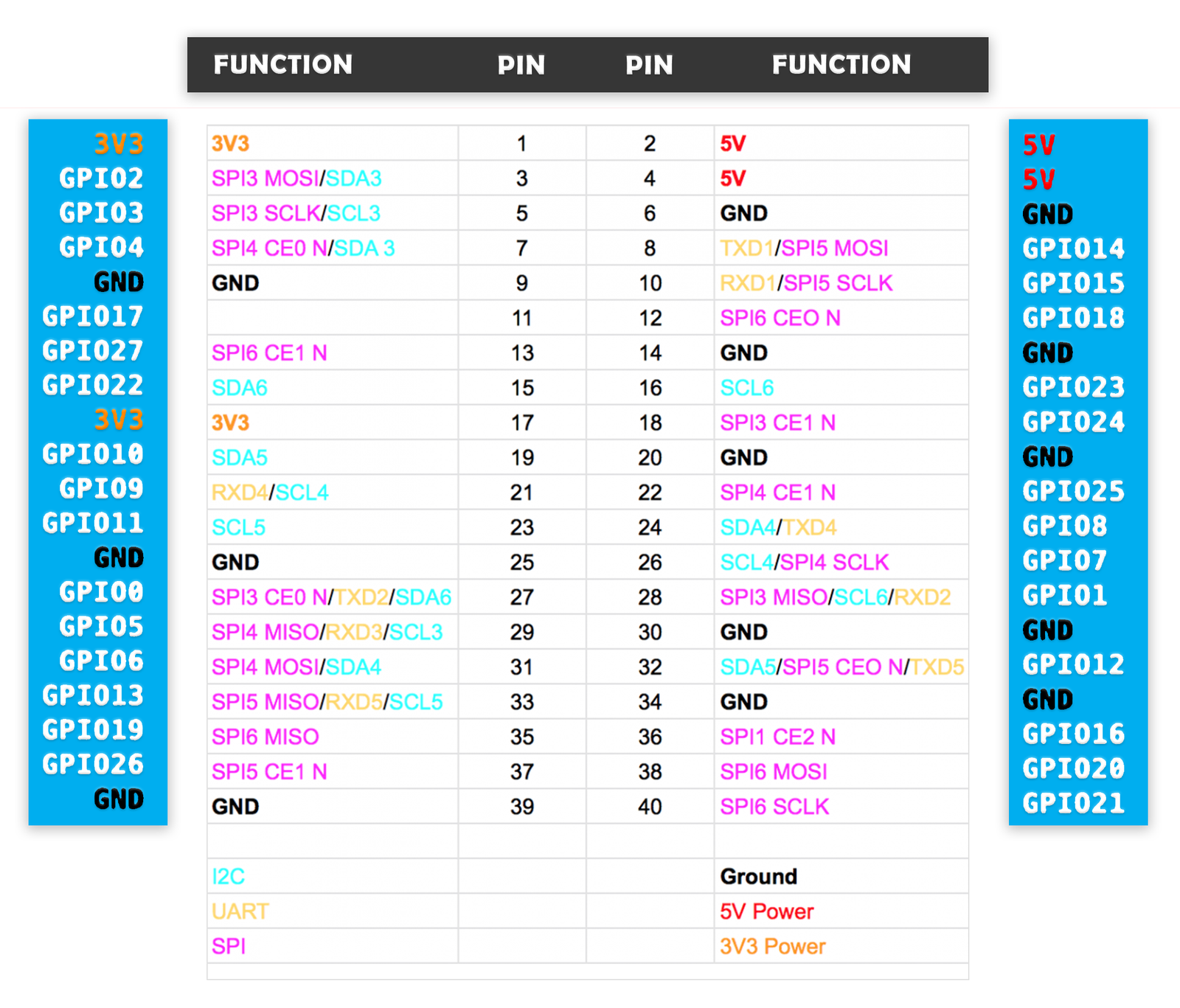
This section includes information on the pinout diagram and headers pins details with an application of each pin.
Raspberry Pi Pins Description
Now let’s discuss pin layout. The pins description is same for all models.
The Raspberry Pi 4 can be used in the external embedded system to communicate. It has a total of 40 pins from which 28 are GPIO pins and the rest of them are power pins. GPIO pins don’t only perform the simple I/O functions. They could give the UART, SPI, and I2C communications. These communications are specific to every pin and all their function are discussed below:
Power Supply Pins
Power In: In Raspberry pi, there is two power in method, one is from the USB-C power port and the second one is from any 5V pin. The 5-volt pin is directly connected to the USB-C adapter port. The input on the 5V pin should be stable and according to its specifications. In the case of higher voltage, the device could get burned. 5V input pins will bypass any fuse and regulator in case of power input, so the power supply from 5V should according to its specification to avoid any kind of harm. The power input pin of the Raspberry Pi 4 is given below:
- Pin2-6 —> +5V
- Pin6 —–> GND
Power Out: There are two types of power output pin in the Raspberry pi 4 3V3 and 5V. 5V is directly connected to the USB port but 3V3 is connected to through the regulator which gives the stable 3 volts output. All power out pins are given below:
- 3V3 – Pin1, Pin17
- 5V – Pin2, Pin6
Ground: Raspberry Pi 4 has multiple ground pin which is connected internally and any ground pin can be used by the power supply or external device to make the common ground. The list of the ground pins is given below:
- Pin6
- Pin9
- Pin14
- Pin20
- Pin25
- Pin30
- Pin34
- Pin39
Digital Input/Output Pins
Almost every device needs to input and output pins to communicate. In this device there are 28 GPIO pins are available these pins can be used for any digital input and output operating. The GPIO pins in the controller have some default values. GPIO pins from 0-9 will be at a HIGH state and from 10 to above the pins will be at a LOW state. All those pins in the Raspberry Pi 4 are given below:
- GPIO0 – Pin27
- GPIO1 – Pin28
- GPIO2 – Pin3
- GPIO3 – Pin5
- GPIO4 – Pin7
- GPIO5 – Pin29
- GPIO6 – Pin31
- GPIO7 – Pin26
- GPIO8 – Pin24
- GPIO9 – Pin21
- GPIO10 – Pin19
- GPIO11 – Pin23
- GPIO12 – Pin32
- GPIO13 – Pin33
- GPIO14 – Pin8
- GPIO15 – Pin10
- GPIO16 – Pin36
- GPIO17 – Pin11
- GPIO18 – Pin12
- GPIO19 – Pin35
- GPIO20 – Pin38
- GPIO21 – Pin40
- GPIO22 – Pin15
- GPIO23 – Pin16
- GPIO24 – Pin18
- GPIO25 – Pin22
- GPIO26 – Pin37
- GPIO27 – Pin13
All GPIO pins in Raspberry Pi 4 are not only for input-output function. Each GPIO pin can be used as other functions, which will be specified through programming.
Raspberry Pi Serial Communication Modules
Raspberry Pi UART Pins
There are multiple kinds of serial communication and UART is one of them. It is quite popular because of its simple communication system and dependence on most of the software. There is multiple UART communication pin in the Raspberry pi 4 and all of them are given below:
- TXD1 – GPIO14 – Pin8
- RXD1 – GPIO15 – Pin10
- TXD2 – GPIO0 – Pin27
- RXD2 – GPIO1 – Pin28
- TXD3 – GPIO5 – Pin29
- RXD3 – GPIO4 – Pin7
- TXD4 – GPIO8 – Pin24
- RXD4 – GPIO9 – Pin21
- TXD5 – GPIO12 – Pin32
- RXD5 – GPIO13 – Pin33
SPI Communication Pins
Some devices use SPI protocol and it could help the controlling device to control multiple devices using single data transmissions wire. In Raspberry pi 4 there are multiple SPI pins that can be used for SPI communication. The SPI pin of Raspberry Pi 4 is given below:
- SPI3 CEO N – GPIO0 – Pin27
- SPI3 MISO – GPIO1 – Pin28
- SPI3 MOSI – GPIO2 – Pin3
- SPI3 SCLK – GPIO3 – Pin5
- SPI4 CEO N – GPIO4 – Pin7
- SPI4 MISO – GPIO5 – Pin29
- SPI4 MOSI – GPIO6 – Pin31
- SPI4 SCLK – GPIO7 – Pin26
- SPI0 CE1 N – GPIO8 – Pin24
- SPI0 CE0 N – GPIO9 – Pin21
- SPI0 MISO – GPIO10 – Pin19
- SPI0 MOSI – GPIO11 – Pin23
- SPI5 CEO N/ SPI0 SCLK – GPIO12 – Pin32
- SPI5 MISO – GPIO13 – Pin33
- SPI5 MOSI – GPIO14 – Pin8
- SPI5 SCLK – GPIO15 – Pin10
- CTS0 – GPIO16 – Pin36
- RTS0 – GPIO17 – Pin11
- SPI6 CEO N – GPIO18 – Pin12
- SPI6 MISO – GPIO19 – Pin35
- SPI6 MOSI – GPIO20 – Pin38
- SPI6 SCLK – GPIO21 – Pin40
I2C Communication Pins
Raspberry Pi 4 also supports the I2C protocol. It is a type of serial communication used by some sensors and motors to communicate. In Pi GPIO pins also gives I2C support. All these pins are given below:
- SDA0/SDA6 – GPIO0 – Pin27
- SCL0/SCL6 – GPIO1 – Pin28
- SDA1/SDA3 – GPIO2 – Pin3
- SCL1/SCL3 – GPIO3 – Pin5
- SDA3 – GPIO4 – Pin7
- SCL3 – GPIO5 – Pin29
- SDA4 – GPIO6 – Pin31
- SCL4 – GPIO7 – Pin26
- SDA4 – GPIO8 – Pin24
- SCL4 – GPIO9 – Pin21
- SDA5 – GPIO10 – Pin19
- SCL5 – GPIO11 – Pin23
- SDA5 – GPIO12 – Pin32
- SCL5 – GPIO13 – Pin33
- SDA6 – GPIO22 – Pin15
- SCL6 – GPIO23 – Pin16
RPi PWM GPIO Pins
To generate the desired pulse output signal Raspberry Pi 4 has some PWM pins. Those pins can be used directly with any low voltage external device to get that signal. To generate signal first the pins should get the instructions first. All PWM pins are given below:
- PWM0 – GPIO12 – Pin32
- PWM1 – GPIO13 – Pin33
- PWM0 – GPIO18 – Pin12
- PWM1 – GPIO19 – Pin35
Raspberry Pi SDIO Pins
In Raspberry Pi 4 there is a slot for SD card but GPIO Pins also support the SD card compatibility. SDIO pins on the device can be used for SD card in case of requirement:
- SD0CLK/SD1 CLK – GPIO22 – Pin15
- SD0 CMD/SD1 CMD – GPIO23 – Pin16
- SD0 DATA0/SD1 DAT0 – GPIO24 – Pin18
- SD0 DAT1/SD1 DAT1 – GPIO25 – Pin22
- SD1 DAT2/SD1 DAT2 – GPIO26 – Pin37
- SD0 DAT3/SD1 DAT3 – GPIO27 – Pin13
You can read
- difference between different Generations of Raspberry Pi Models
- Difference Between Raspberry Pi and Arduino
Raspberry Pi 4 Features and Specifications
| FEATURES & SPECIFICATIONS | |
|---|---|
| CPU | Quad core Cortex-A72 (64-bit) @ 1.5GHz |
| GPU | H264 (1080p60 decode, 1080p30 encode) OpenGL ES 3.0 graphics, H.265 (4kp60 decode) |
| RAM | 1GB, 2GB, 4GB. |
| Operating Voltage Range | 5V with 3A minimum |
| GPIO PORTS | 28 I/O Pins |
| LAN | Available |
| PoE | Enable |
| WIFI | Available |
| Bluetooth | 5.0 |
| SD Card | Available |
| HDMI | 2- Port with 4k Display (mini-HDMI) |
| PWR Exp Header | Not Available |
| Power Source | DC Power Jack, mini USB-C Port |
| Expansion Connectors | 40 Pins (SPI, I2C, LCD, UART, PWM, SDIO) |
| USB | 2×2.0, 2×3.0 |
| Camera | CSI |
| Display | DSI |
| Operating Temperature | 0 – 50 degree |
Raspberry Pi Applications
- Raspberry Pi can be used as a hub in Home Automation.
- It can be used as a server for a small network.
- Pi also uses in robotics and other embedded systems.
Raspberry pi 4 Board Description
There is multiple peripheral support by Raspberry Pi 4 which can be used:
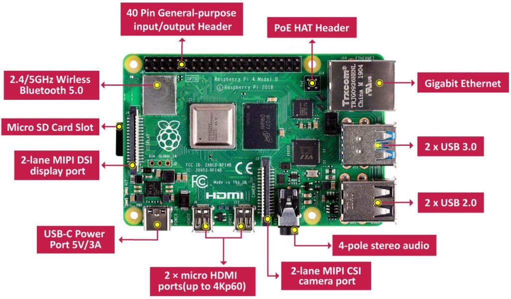
Modern Communication Support
Raspberry Pi 4 has all modern communication systems. It has internal WiFi and Bluetooth for wireless data communication. It can be used with internal at anywhere without any disturbance. The Pi can be moved easily within the same network due to fast WiFi support. The device also has LAN support in case WiFi is not available and the network is following the wired communication method to communicate.
- LAN – Gigabyte Ethernet
- Bluetooth – 5.0
- WiFi – 2.4 with 5GHz speed
Rpi HDMI Interface Feature
In previous Pi devices, there was only one HDMI port and it also has low graphics, but in the latest model there two mini HDMI ports that can be used at the same time for multiple desktop views. Both ports give a 4K ULTRA HD view to the user. It never feels that the user is viewing a mini-size computer.
- GPU SPECS – H264 (1080p60 decode, 1080p30 encode) OpenGL ES 3.0 graphics, H.265 (4kp60 decode)
Rpi other Main Peripherals
USB: There are four USB ports in Raspberry Pi 4. Two ports have 2.0 support only but the remaining two are 3.0. These 3.0 support givens users to transfer data quickly.
PoE Header: Due to increase the usage of Raspberry Pi in IoT and other smart projects the PoE Header has also come within the Pi. The one board PoE allows the users to pass the power to the device through Ethernet Wire. In the case of PoE, an external PoE HAT will be required.
Camera: The device has camera support. It has a two-lane MIPI CSI camera port which can be used to connect the pi directly with the cameras and use them without any third interface.
Display: The Raspberry Pi 4 can be connected to an external LCD. It doesn’t use the expansion header to communicate with LCDs like other devices. It has a separate 2 lane MIPI DSI port which can be used to communicate with external compatible LCD.
Audio: The audio data can be travel from pi to the display device through HDMI but it has a separate 4 pole audio port that can be used to send and receive an audio signal. The signal from the device can be used by the internal program or any other device at the expansion header.
SD CARD: It is the most required part of the Raspberry Pi. The OS of the Pi will be placed within the SD card and then the card will be used through the SD Card slot.
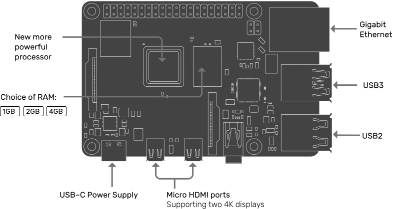
Raspberry Pi 2D Diagram
These two pictures are physical 2D model diagrams of RPi. You might need these dimension pictures for your PCB design.

None of your diagrams seem to show me where the pins are? I need to connect a fan to pins 2 and or 3 which are these please? We are told 5v which is positive and which is negative
Check this image given at the start of the article
http://microcontrollerslab.com/wp-content/uploads/2019/12/Raspberry-Pi-pinout.png
That picture only only shows the names & funtions of the pins. It doesn’t show WHERE they are.
You are looking for the ’40 pin general-purpose input/output header’. It is at the edge of the PCB, 20 pins long and 2 pins wide. the even pins are on one side the odd on the other. This should help you find more description.
You mention the 5v power supply pins – that is, where you can provide power TO the board – are pins 2 and 3, and again mention pins 2 and 3 for 5v out, but the diagram just above that looks like those should be listed as pins 2 and 4. Pin 3 is labeled GPIO2. Was that just a typo, or is the diagram labeling the pins incorrect?
Hi Gerge,
It was a typo. We just fixed it.