Recommended Components
The following components are used in this project or are helpful for getting started with Raspberry Pi Pico development.
| Component | How it’s used in this project | Buy on Amazon |
|---|---|---|
| Raspberry Pi Pico | The RP2040 microcontroller board used in this tutorial. | Check Price |
| HC-05 Bluetooth Module | HC-05 Bluetooth-to-serial module. | Check Price |
| LED Assortment Kit | Assorted LEDs used in the examples. | Check Price |
| Breadboard | Solderless breadboard for building the circuit. | Check Price |
| Jumper Wires | Male-to-male / male-to-female wires for the connections. | Check Price |
As an Amazon Associate we earn from qualifying purchases. Prices and availability are accurate as of the date/time indicated and are subject to change.
Prerequisites
Before we start this lesson, make sure you are familiar with and have the latest version of Python 3 installed on your system, and that MicroPython is set up on your Raspberry Pi Pico. Additionally, you should have a working Integrated Development Environment (IDE) for programming. We will be using Thonny IDE throughout this tutorial.If you are using uPyCraft IDE, you can check this getting started guide:Bluetooth Terminal Application
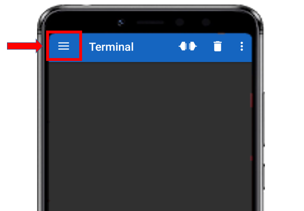
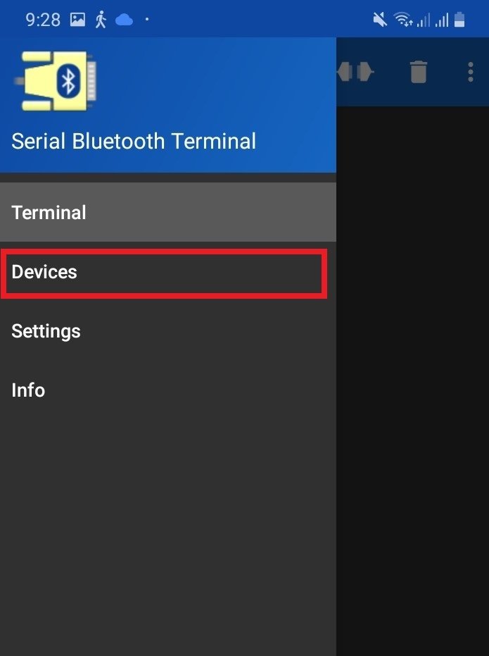
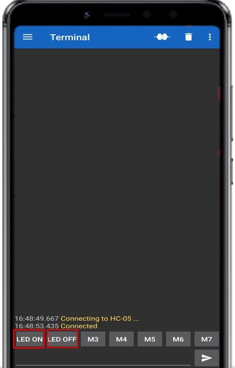
Throughout this guide, we will use an Android smartphone to connect to our Raspberry Pi Pico. Make sure you have an Android phone available. We will also use a Bluetooth terminal application to pair the two devices together.Go to the Play Store and download the application named Serial Bluetooth Terminal. This is shown in the figure below.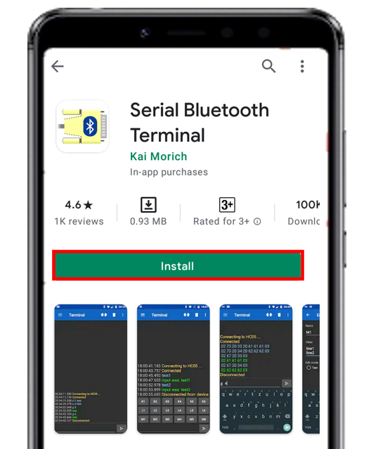
HC-05 Introduction
The HC-05 is one of the most commonly used Bluetooth modules that operates on the UART communication protocol. It stands out from other Bluetooth devices because of its versatile pin configuration and dual operating modes. The module normally communicates via UART serial at 9600 baud rate by default. However, it can be configured using AT commands and supports baud rates of 9600, 19200, 38400, 57600, 115200, 230400, and 460800.One of the most important features of the HC-05 is its ability to work in both Master and Slave modes. In slave mode, the module waits for an incoming connection from a master device such as a smartphone or another Bluetooth module. In master mode, the module actively initiates a connection with another Bluetooth device. This makes HC-05 extremely flexible for a wide range of wireless communication applications.The module operates in the 2.4GHz ISM band and uses the Bluetooth 2.0 standard with Enhanced Data Rate (EDR). It has a typical communication range of about 10 meters in open space, though this can vary based on obstacles and interference. The HC-05 module is based on the CSR BC417 chip and comes pre-configured with firmware that makes it simple to use in UART passthrough mode.
Recommended Reading: HC-05 Bluetooth Module
Pinout
The HC-05 module has multiple pins and status indicators that help control different operations. The pinout diagram below shows all available pins.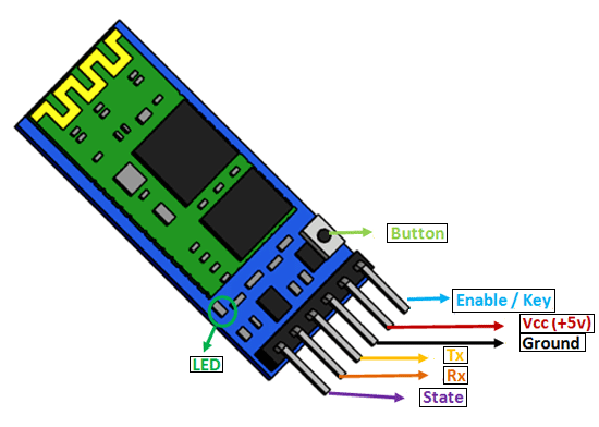
| Pin | Description |
| VCC | The operating voltage is 3.3V. However, the I/O pins can tolerate up to 5V. Therefore, you can connect a 5V power source to this pin, and the TX/RX pins can also work with 5V logic signals. |
| GND | The ground reference of both the microcontroller and HC-05 must be at the same level. Connect the power supply, HC-05, and Raspberry Pi Pico ground pins together. |
| Tx | Transmitter pin for UART communication. This pin transmits data from the HC-05 module to the microcontroller. |
| Rx | Receiver pin for UART communication. This pin receives data from the microcontroller and transmits it via Bluetooth. |
| State | Indicates the current connection state of the Bluetooth module. It has an internal connection to the onboard LED to visually show the working status of the HC-05. |
| Enable/Key | Used to switch between data mode and AT command mode. A HIGH input puts the device in command mode; a LOW input puts it back in data mode. The default is data mode. |
| Button | A physical button on the module that can also toggle between command and data modes. |
| LED | Shows the working status of the module along with the State pin. |
HC-05 AT Command Mode
One of the most powerful features of the HC-05 is its built-in AT command interface. AT commands allow you to configure the module’s settings such as its name, baud rate, pairing PIN, and operating mode. To enter AT command mode, hold the button on the HC-05 module while powering it on. The onboard LED will blink slowly (approximately once every two seconds) to indicate that the module is in AT command mode.Some commonly used AT commands for the HC-05 include:- AT – Tests the communication link. The module responds with “OK”.
- AT+NAME=MyDevice – Changes the Bluetooth device name to “MyDevice”.
- AT+PSWD=1234 – Changes the pairing PIN to “1234”.
- AT+UART=9600,0,0 – Sets the baud rate to 9600.
- AT+ROLE=0 – Sets the module to slave mode (0 = slave, 1 = master).
- AT+RESET – Resets the module and applies new settings.
Interfacing HC-05 with Raspberry Pi Pico
In this section, we will show you how to connect the HC-05 module to the Raspberry Pi Pico. The connection is straightforward since we will be using the UART serial interface, which only requires two data lines: TX and RX. The Raspberry Pi Pico has two UART channels: UART0 and UART1. The figure below shows the available RX and TX pin options on the board.
LED Control Example with HC-05, Raspberry Pi Pico, and Android App
For demonstration purposes, we will control a Raspberry Pi Pico GPIO pin with an LED connected to it. This will be done via the Android application through the Bluetooth module. We will toggle the LED by pressing buttons configured inside the Android application.Required Components:- Raspberry Pi Pico
- HC-05 Bluetooth Module
- 5mm LED
- 220-ohm resistor
- Connecting Wires
- Breadboard
Schematic: Raspberry Pi Pico and HC-05
Follow the schematic diagram below to connect all the components together.The HC-05 module has two serial data pins. The TX pin of the HC-05 connects to the RX pin of the Raspberry Pi Pico (GP1), and the RX pin of the HC-05 connects to the TX pin of the Raspberry Pi Pico (GP0). We are using UART0 for this example. The VCC pin of the HC-05 connects to the 5V supply pin of the Raspberry Pi Pico, and both grounds are connected together.The anode of the LED connects to GP2 of the Raspberry Pi Pico, and the cathode connects to GND through a 220-ohm current-limiting resistor. All ground pins are tied to a common ground.
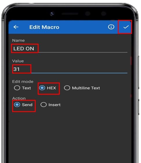
Setting up the Android App
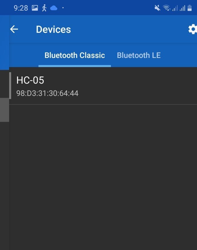
In your smartphone settings, enable Bluetooth and scan for available devices. You should see the HC-05 in the list. The default device name is “HC-05”, and the default pairing PIN is either “0000” or “1234”.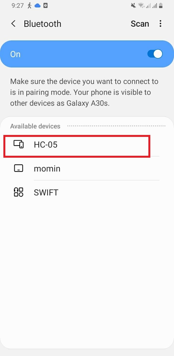


MicroPython: Raspberry Pi Pico LED Control with HC-05 and Android App
from machine import Pin, UART
uart = UART(0, 9600)

Led_pin = 2
led = Pin(Led_pin, Pin.OUT)

while True:
    if uart.any():
        data = uart.readline()
        print(data)
        if data == b'1':
            led.high()
            print("LED is now ON!")
        elif data == b'0':
            led.low()
            print("LED is now OFF!")
How the Code Works
We begin by importing thePin and UART classes from the machine module.from machine import Pin, UARTUART(), passing the UART channel number (0) as the first argument and the baud rate (9600) as the second argument. This initializes UART0 to communicate at 9600 baud with the HC-05 module.uart = UART(0, 9600)Led_pin = 2
led = Pin(Led_pin, Pin.OUT)while loop, we continuously check whether any data has been received on the UART channel using uart.any(). If data is available, we read it with uart.readline() and store it in the variable data.while True:
if uart.any():
data = uart.readline()
print(data)b'1' is received. When ‘LED OFF’ (M2) is pressed, b'0' is received. We use if-elif statements to act on these values accordingly. The b prefix indicates a bytes object, which is what MicroPython’s UART returns. if data == b'1':
led.high()
print("LED is now ON!")
elif data == b'0':
led.low()
print("LED is now OFF!")Extending the Project: Controlling Multiple Outputs
The example above controls a single LED, but the same principle can be extended to control multiple GPIO pins or even more complex outputs. For example, you could add more buttons in the Serial Bluetooth Terminal app and map each button to a different GPIO pin. Below is an extended version of the code that controls three LEDs connected to GP2, GP3, and GP4.from machine import Pin, UART
uart = UART(0, 9600)
led1 = Pin(2, Pin.OUT)
led2 = Pin(3, Pin.OUT)
led3 = Pin(4, Pin.OUT)
while True:
    if uart.any():
        data = uart.readline()
        print(data)
if data == b'1':
led1.high()
print("LED 1 ON")
elif data == b'2':
led1.low()
print("LED 1 OFF")
elif data == b'3':
led2.high()
print("LED 2 ON")
elif data == b'4':
led2.low()
print("LED 2 OFF")
elif data == b'5':
led3.high()
print("LED 3 ON")
elif data == b'6':
led3.low()
print("LED 3 OFF")Troubleshooting Tips
If you encounter issues with the HC-05 and Raspberry Pi Pico connection, here are some common problems and their solutions:- HC-05 not detected by the phone: Make sure the HC-05 is powered correctly. The VCC pin must be connected to 5V (not 3.3V). The onboard LED should blink rapidly when the module is on and waiting for a connection.
- Connection drops frequently: This usually indicates interference or a weak power supply. Make sure your power supply can provide adequate current. The HC-05 can draw up to 30mA during active Bluetooth transmission.
- No data received in Thonny: Double-check that TX of HC-05 is connected to the RX pin of Raspberry Pi Pico and RX of HC-05 is connected to the TX pin of Raspberry Pi Pico. A common mistake is swapping these connections.
- Incorrect byte values received: Always print the raw received data first to confirm what the app actually sends before adding logic to control outputs. Different app versions or button configurations may send different byte sequences or include a newline character.
- Module not entering AT mode: Ensure you press and hold the button on the HC-05 before and during power-up. The LED blinking pattern changes from fast to slow when AT mode is active.
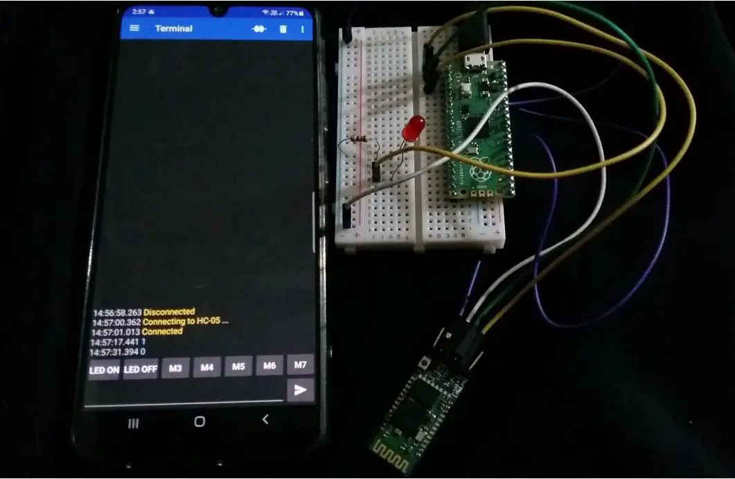
Demonstration
After connecting the HC-05 module and uploading the code, click the LED ON button in the app. The LED will turn on, and you will see a “LED is now ON!” message in the Thonny shell terminal. The value ‘1’ will also appear in the app’s terminal window.
- HC06 Bluetooth Module Guide with Arduino Interfacing
- HC-05 Bluetooth Interfacing with TM4C123G Tiva C Launchpad – Keil uvision
- HM-10 Bluetooth Module – Interfacing Example with Arduino
- Introduction to Bluetooth Low Energy
- Control 2 DC Motors via Bluetooth and Arduino
- Bluetooth Based Home Automation
- Bluetooth based DC Motor Speed and Direction Control using Arduino
- HC-05 Bluetooth Module Interfacing with Arduino
- Bluetooth Module HC-05 Interfacing with PIC Microcontroller
- Bluetooth Controlled Robot using PIC Microcontroller