In this tutorial, we will learn to interface an HC-05 Bluetooth module with TM4C123 Tiva C Launchpad. This Bluetooth device operates on UART communication. In other words, it uses serial communication to transmit and receive data serially over standard Bluetooth radio frequency. Therefore, we will use a UART module of TM4C123GH6PM microcontroller to interface HC-05 with Tiva C Launchpad.
In this tutorial, we will use an android application to communicate with the TM4C123 Tiva launchpad through the HC-05 Bluetooth module. First, we will see an example to send and receive generic text messages between Android application and TM4C123 using Bluetooth wireless communication. Secondly, we will see an example to control an LED from an Android application. The LED will be connected with a GPIO pin of the TM4C123GH6PM microcontroller.
Tiva C Launchpad comes with TM4C123GH6PM microcontroller. If you want an overview of Tiva Launchpad, read this tutorial:
Pre-requisites:
- How to Download and Install Keil uVision for ARM and 8051
- Getting started with Keil uVision: Write your first Program for Tiva LaunchPad
Recommended Components
The following components are used in this project or are helpful for getting started with TM4C123 Tiva C LaunchPad development.
| Component | How it’s used in this project | Buy on Amazon |
|---|---|---|
| TM4C123G Tiva C LaunchPad | The Tiva C board communicating with the HC-05 over UART5. | Check Price |
| Micro USB Cable | Connects the LaunchPad’s onboard debugger to your PC for programming and power. | Check Price |
| HC-05 Bluetooth Module | The Bluetooth-to-serial module for wireless communication with the Android app. | Check Price |
| Breadboard | Solderless breadboard for building the circuit. | Check Price |
| Jumper Wires | For wiring the HC-05 to the LaunchPad’s UART pins. | Check Price |
As an Amazon Associate we earn from qualifying purchases. Prices and availability are accurate as of the date/time indicated and are subject to change.
HC-05 Introduction
HC-05 is a two-way full-duplex Bluetooth to serial module. In other words, it uses UART serial communication to transmit and receive data packets through a classic Bluetooth standard. Its CSR Bluecore 04-External single chip is already configured to communicate with other Bluetooth devices through serial communication.
The default baud rate set for HC-05 is 9600. But it can be programmed with AT commands and it supports 9600,19200,38400,57600,115200,230400,460800 baud rates.
If you don’t know about baud rate, you should read this UART communication tutorial:
In short, this module can be used to perform low-cost wireless communication between microcontrollers such as Arduino, TM4C123, Pic Microcontroller, Raspberry Pi, BeagleBone, STM32, and Arduino Mega, etc. Also, we can use it for communication between a microcontroller and PC or Android application. There are many Android applications available in the Google Play store which we can use to send and receive data to/from HC05.
Pinout diagram
The following figure shows the pinout diagram of the HC-05 Bluetooth module. Its output header contains six pins; namely Enable/Key, Vcc, GND, Tx, Rx, state. The description of all these pins are given in the next section.
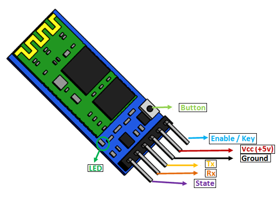
HC-05 Pin configuration details
The details of all pins and their working is given below:
VCC Pin
The operating voltage range is 3.3 volts. But I/O pins can withstand voltage of up to 5 volts. Therefore, we can connect 5 volts power source to this pin, and also other pins can also operate on 5 volts signals such as Tx and Rx signals.
GND Pin
Ground reference of both TM4C123 and HC-05 should be at the same level. Therefore, we should connect a power supply, HC05, and TM4C123 ground pins to each other.
TX Pin
As discussed earlier, the HC-05 Bluetooth module uses UART communication to transmit data. This is a transmitter pin. Whenever the Bluetooth module will receive data, it transmits data to TM4C123 through Tx pin.
RX Pin
This pin is a data receiving the pin in UART communication. It is used to receive data from the microcontroller and transmits it through Bluetooth.
State Pin
The state shows the current state of the Bluetooth. It gives feedback to the controller about the connectivity of Bluetooth with another device. This pin has an internal connection with the onboard LED which shows the working of HC05.
Enable/Key Pin
Using an external signal, Enable/Key pin is used to change the HC-05 mode between data mode and command mode. The HIGH logic input will transfer the device in command mode and the LOW logic input will change the mode to data mode. By default, it works in data mode.
Button Pin
The command and data mode states are changeable through a button present on the module.
LED Pin
As mentioned earlier, this pin shows the working status of module along with State pin.
HC-05 Interfacing with TM4C123 Tiva Launchpad
After discussing the basics and introductory concepts of HC-05 Bluetooth module, let’s come to the main topic of this tutorial that is interfacing with TM4C123 Tiva C Launchpad.
UART Pins
As you know, in order to communicate with the HC-05 Bluetooth module, we need to use a UART communication port of the TM4C123GH6PM microcontroller. This microcontroller has on-chip 5 UART ports such as UART0 to UART5. We can use any one of these UART ports to interface TM4C123 with the BT device.
The following table shows all UART ports of TM4C123 Tiva launchpad and their corresponding GPIO pins.
| UART Module | Rx Pin | Tx Pin |
|---|---|---|
| UART0 | PA0 | PA1 |
| UART1 | PC4 | PC5 |
| UART2 | PD6 | PD7 |
| UART3 | PC6 | PC7 |
| UART4 | PC4 | PC5 |
| UART5 | PE4 | PE5 |
| UART6 | PD4 | PD5 |
| UART7 | PE0 | PE1 |
HC-05 and TM4C123 Connection Diagram
In this tutorial, we will use a UART5 port. For the UART5 port, the PE4 GPIO pin is a receiver pin (Rx) and the PE5 pin is a transmitter pin (Tx).
Now make connections with HC-05 Bluetooth module and Tiva Launchpad according to this schematic diagram.
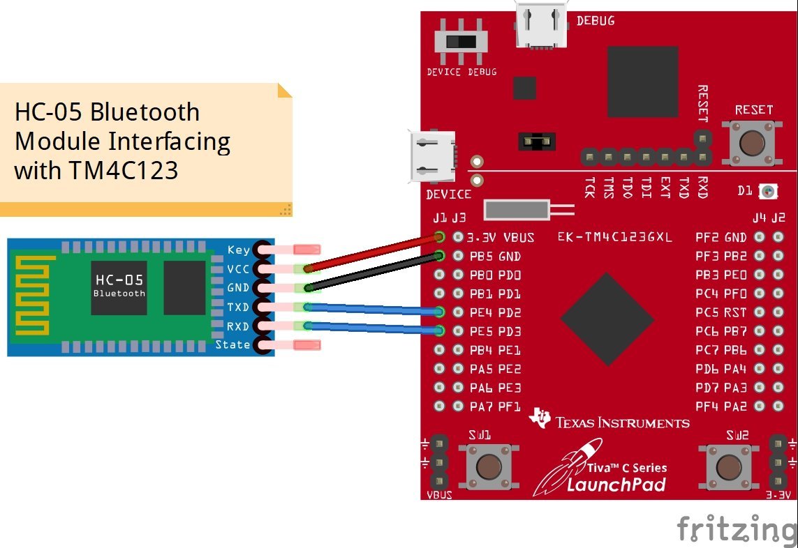
| HC-05 | TM4C123 |
|---|---|
| Tx | PE4 (Rx5) |
| Rx | PE5 (Tx5) |
| Vcc | 3.3 volts |
| GND | GND |
In this tutorial, we will use the UART5_Receiver() and UART5_Transmitter() functions which we developed in the last tutorial. The UART5_Receiver() routine is used to read data which will receive on PE4(Rx5) pin of TM4C123 and the UART5_Transmitter() routine is used to transmit data serially using PE5(Tx5) pin of Tiva Launchpad.
For more information on UART modules and their programming, read this article:
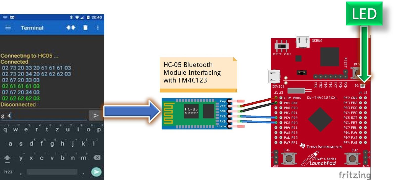
LED Control Example with HC-05 and Andriod App
For demonstration purposes, we will control an on board LED of TM4C123 through an android application. We will not use external LEDs and use onboard LEDs of TM4C123.
TM4C123 Tiva Launchpad has an RGB LED connected with PF1, PF2, and PF3 pins. We will send ON/OFF commands from an Android application. Based on these commands, LEDs will turn on or off.
In the previously published tutorials, we learned to control onboard LEDs of TM4C123 manually using a push button. You can read about these tutorials here:
Andriod Bluetooth Terminal App
Android Application
To communicate between Android mobile and HC-05 Bluetooth modules which will be interfaced with TM4C123 Tiva Launchpad, we will need an Android application. There are many Bluetooth terminal Android applications available in google play store. For this tutorial, we will use a “Serial Bluetooth Terminal” Android application. It is a command line console application which is used to transmit and receive data over UART interface from other Bluetooth devices such as HC-05, HC-06 etc.
Go to this download link and install this application on your Android based smart phone.
Code
This demo code turns LEDs ON/OFF according to the commands received from the Android application by the TM4C123 microcontroller through HC-05 Bluetooth module.
#include "TM4C123.h"
#include <stdint.h>
#include <stdlib.h>
void Delay(unsigned long counter); // used to add delay
void HC05_init(void); // Initialize UART5 module for HC-05
char Bluetooth_Read(void); //Read data from Rx5 pin of TM4C123
void Bluetooth_Write(unsigned char data); // Transmit a character to HC-05 over Tx5 pin
void Bluetooth_Write_String(char *str); // Transmit a string to HC-05 over Tx5 pin
int main(void)
{

	HC05_init(); // call HC05_init() to initialze UART5 of TM4C123GH6PM

	/* Set PF1, PF2 and PF3 as digital output pins */

	SYSCTL->RCGCGPIO |= 0x20;   /* enable clock to GPIOF */
    GPIOF->DIR |= 0x0E;         //set PF1, PF2 and PF3 as digital output pin
    GPIOF->DEN |= 0x0E;         // CON PF1, PF2 and PF3 as digital GPIO pins
  	Delay(10);

	while(1)
	{
		char c = Bluetooth_Read();          /* get a character from UART5 */

/* Check the received character and take action to control onboard LEDs of TM4C123 */
/* Send status string to Andriod app after turning on/off LEDs */

        if( c=='A'){
			GPIOF->DATA |=(1<<1);
			Bluetooth_Write_String("RED LED ON\n");
		}
		else if( c=='B'){
			GPIOF->DATA &=~(1<<1);
			Bluetooth_Write_String("RED LED OFF\n");
		}
		else if( c=='C'){
			GPIOF->DATA |=(1<<2);
			Bluetooth_Write_String("BLUE LED ON\n");
		}
		else if( c=='D'){
			GPIOF->DATA &=~(1<<2);
			Bluetooth_Write_String("BLUE LED OFF\n");
		}
		if( c=='E'){
			GPIOF->DATA |=(1<<3);
			Bluetooth_Write_String("GREEN LED ON\n");
		}
		else if( c=='F'){
			GPIOF->DATA &=~(1<<3);
			Bluetooth_Write_String("GREEN LED OFF\n");
		}
	}
}

void HC05_init(void)
{
	SYSCTL->RCGCUART |= 0x20;  /* enable clock to UART5 */
    SYSCTL->RCGCGPIO |= 0x10;  /* enable clock to PORTE for PE4/Rx and RE5/Tx */
    Delay(1);
    /* UART0 initialization */
    UART5->CTL = 0;         /* UART5 module disbable */
    UART5->IBRD = 104;      /* for 9600 baud rate, integer = 104 */
    UART5->FBRD = 11;       /* for 9600 baud rate, fractional = 11*/
    UART5->CC = 0;          /*select system clock*/
    UART5->LCRH = 0x60;     /* data lenght 8-bit, not parity bit, no FIFO */
    UART5->CTL = 0x301;     /* Enable UART5 module, Rx and Tx */

    /* UART5 TX5 and RX5 use PE4 and PE5. Configure them digital and enable alternate function */
    GPIOE->DEN = 0x30;      /* set PE4 and PE5 as digital */
    GPIOE->AFSEL = 0x30;    /* Use PE4,PE5 alternate function */
    GPIOE->AMSEL = 0;    /* Turn off analg function*/
    GPIOE->PCTL = 0x00110000;     /* configure PE4 and PE5 for UART */
}
char Bluetooth_Read(void)
{
    char data;
	  while((UART5->FR & (1<<4)) != 0); /* wait until Rx buffer is not full */
    data = UART5->DR ;  	/* before giving it another byte */
    return (unsigned char) data;
}

void Bluetooth_Write(unsigned char data)
{
    while((UART5->FR & (1<<5)) != 0); /* wait until Tx buffer not full */
    UART5->DR = data;                  /* before giving it another byte */
}

void Bluetooth_Write_String(char *str)
{
  while(*str)
	{
		Bluetooth_Write(*(str++));
	}
}

void Delay(unsigned long counter)
{
	unsigned long i = 0;

	for(i=0; i< counter; i++);
}
Commands used to control onboard LEDs of Tiva Launchpad are listed below:
| Command From App | Function |
|---|---|
| A | Green LED ON |
| B | Green LED OFF |
| C | RED LED ON |
| D | RED LED OFF |
| E | BLUE LED ON |
| F | BLUE LED OFF |
For example, if we send the character ‘A’ from the Android app to HC-05 the green LED of Tiva Launchpad will turn on. Similarly, if we transmit ‘B’ from the Android app to HC-05 green LED of Tiva Launchpad will turn off. Likewise, commands for the other two LEDs are mentioned in the above table.
Demo
Now create a new project in Keil uvision and compile the above given code. After that upload the generated hex file to Tiva Launchpad.
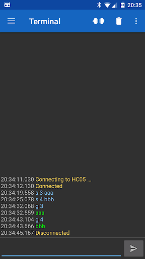
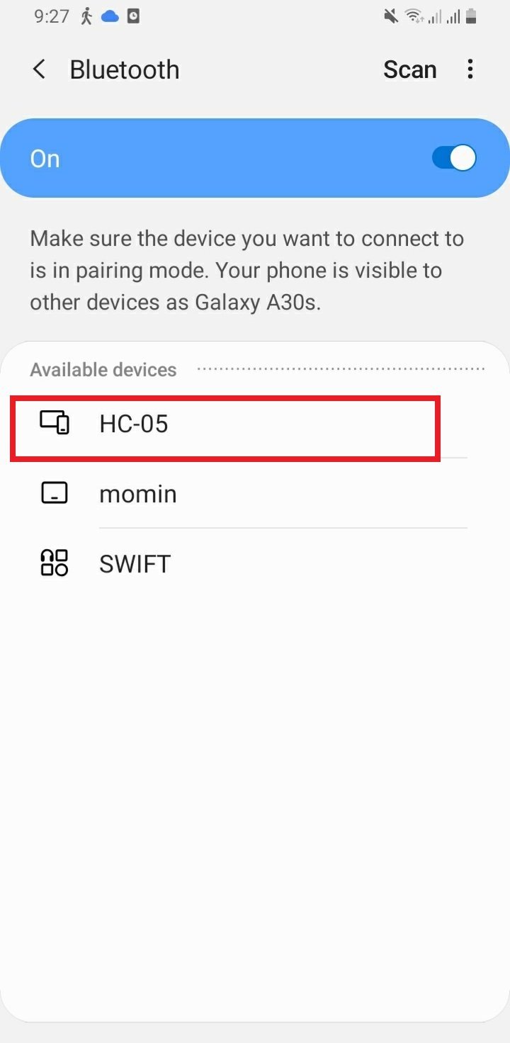
After that turn on Bluetooth of your smartphone or Android based mobile and scan for available Bluetooth devices. You will see the HC-05 device in your scanned list. The default name for this Bluetooth device is “HC-05” and the default pin code is either “0000” or “1234”.
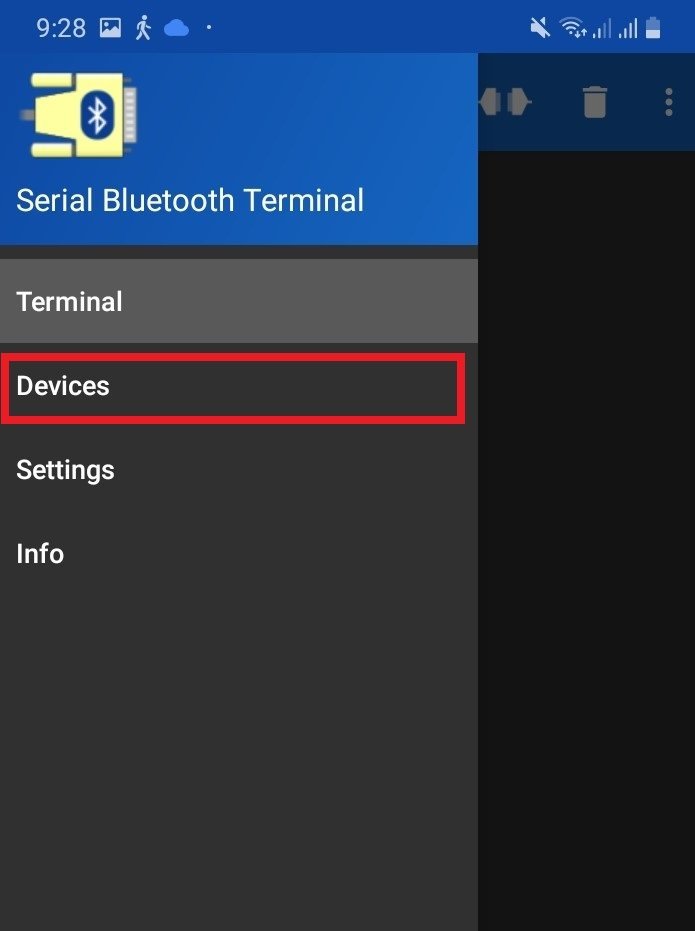
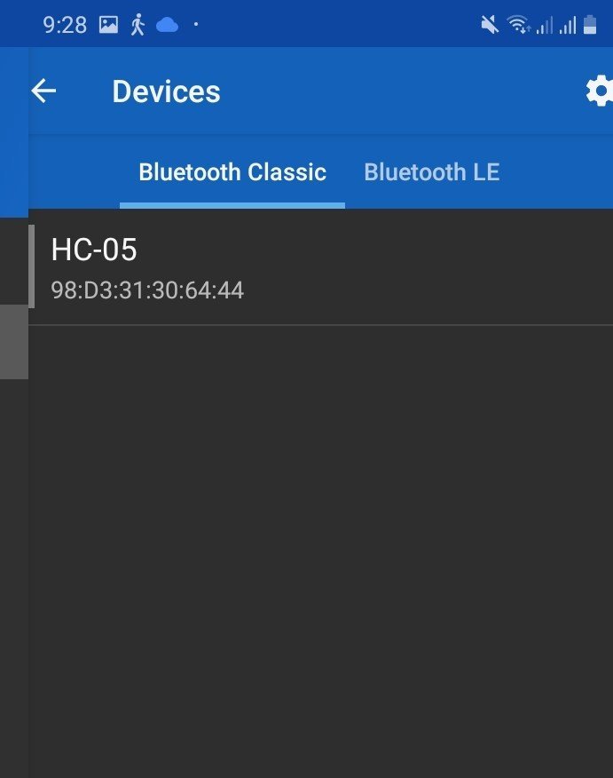
Now open your serial Bluetooth terminal Android application and click on menu->devices. You will find the list of available nearby Bluetooth devices.
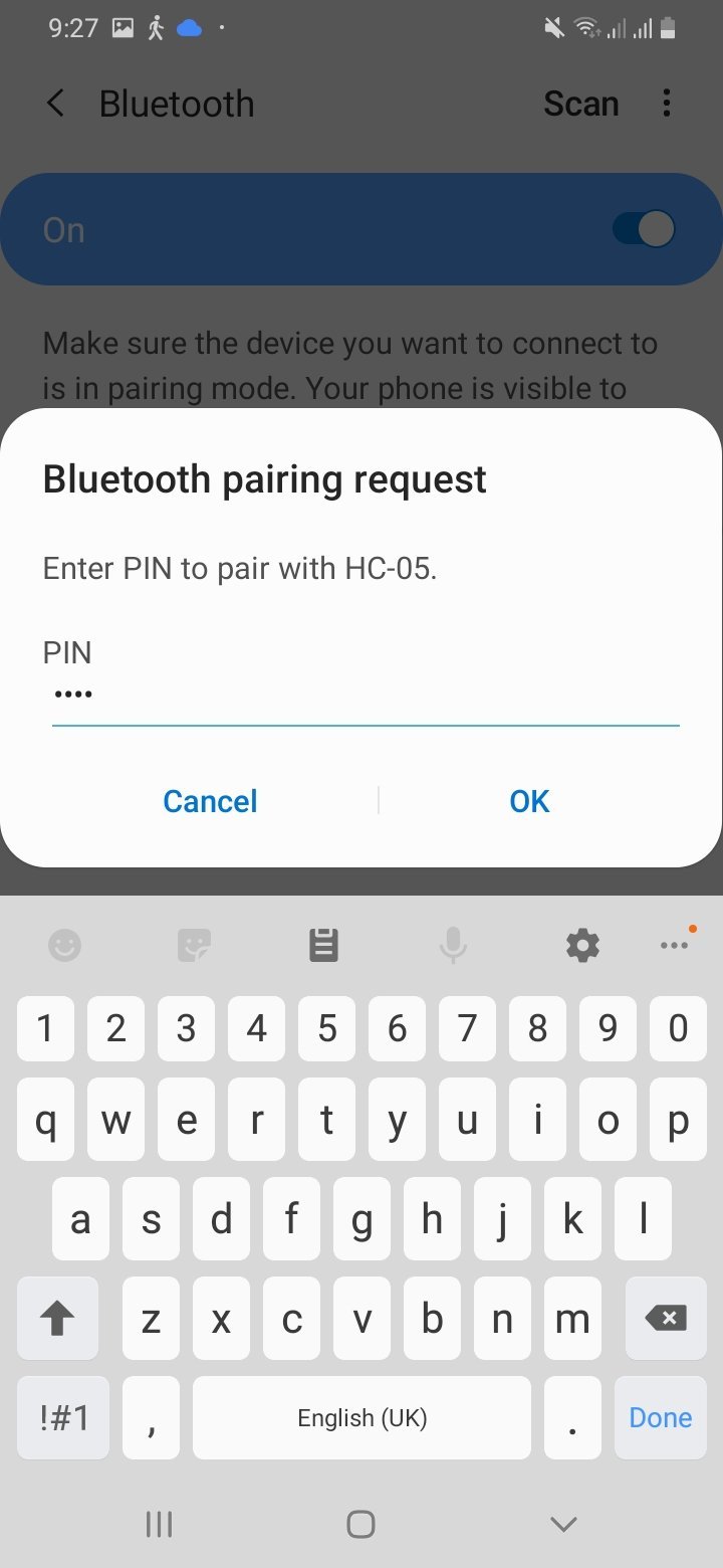
Select HC-05 and the serial Bluetooth terminal starts to pair with HC-05. It will ask for the pin code and enter the pin code mentioned above.
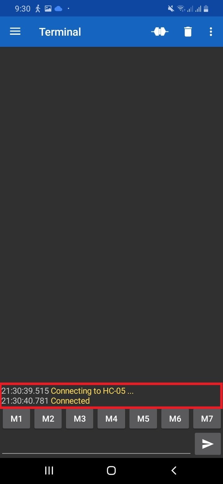
After pairing, it will show a successful connection message.
Now Type ‘A’ and click on the send button, you will see a green LED will turn on. In response, TM4C123 microcontroller sends an acknowledgement message and you will get a “Green LED ON” message on the Bluetooth terminal app. Similarly, if you send ‘B’ a green LED will turn off and you will get a “GREEN LED OFF” response message from TM4C123 Tiva Launchpad.
Similarly, you can send other commands to turn on/off red and blue LEDs.
How Code works
First we add the register definitiom file and required header files in the source code.
#include "TM4C123.h"
#include <stdint.h>
#include <stdlib.h>
These are function prototypes for Bluetooth data for different functions such as UARTmodule initialization, data write, read, and string to/from HC-05. The working functionality of all these functions is mentioned below.
void Delay(unsigned long counter); // used to add delay
void HC05_init(void); // Initialize UART5 module for HC-05
char Bluetooth_Read(void); //Read data from Rx5 pin of TM4C123
void Bluetooth_Write(unsigned char data); // Transmit a character to HC-05 over Tx5 pin
void Bluetooth_Write_String(char *str); // Transmit a string to HC-05 over Tx5 pin
HC05_init() routine configures and enables the UART5 module of TM4C123 Tiva launchpad. PE4 and PE5 pins of TM4C123 Tiva launchpad are Rx and Tx pins to serially communicate with HC-05. All information on the UART5 module configuration registers is explained in our last tutorial on UART communication of TM4C123.
void HC05_init(void)
{
	SYSCTL->RCGCUART |= 0x20;  /* enable clock to UART5 */
    SYSCTL->RCGCGPIO |= 0x10;  /* enable clock to PORTE for PE4/Rx and RE5/Tx */
    Delay(1);
    /* UART0 initialization */
    UART5->CTL = 0;         /* UART5 module disbable */
    UART5->IBRD = 104;      /* for 9600 baud rate, integer = 104 */
    UART5->FBRD = 11;       /* for 9600 baud rate, fractional = 11*/
    UART5->CC = 0;          /*select system clock*/
    UART5->LCRH = 0x60;     /* data lenght 8-bit, not parity bit, no FIFO */
    UART5->CTL = 0x301;     /* Enable UART5 module, Rx and Tx */

    /* UART5 TX5 and RX5 use PE4 and PE5. Configure them digital and enable alternate function */
    GPIOE->DEN = 0x30;      /* set PE4 and PE5 as digital */
    GPIOE->AFSEL = 0x30;    /* Use PE4,PE5 alternate function */
    GPIOE->AMSEL = 0;    /* Turn off analg function*/
    GPIOE->PCTL = 0x00110000;     /* configure PE4 and PE5 for UART */
}
Bluetooth_Read() function reads a character from the Rx5 pin of TM4C123 and returns a received character. This method uses a polling based method. We keep polling UART5->FR bit4 to check its data is available on the Rx5 pin. If it is available, we read the data from UART5->DR register and save it inside the character type variable. At the end return statement, returns the received character.
char Bluetooth_Read(void)
{
    char data;
	  while((UART5->FR & (1<<4)) != 0); /* wait until Rx buffer is not full */
    data = UART5->DR ;  	/* before giving it another byte */
    return (unsigned char) data;
}
Bluetooth_Write() function is used to transmit a character to the Bluetooth module over the Tx5 pin of the launchpad. It only checks if the Tx buffer is empty and if it is. Put the character data to Tx buffer.TM4C123 transmits data available in Tx buffer.
void Bluetooth_Write(unsigned char data)
{
    while((UART5->FR & (1<<5)) != 0); /* wait until Tx buffer not full */
    UART5->DR = data;                  /* before giving it another byte */
}
Bluetooth_Write_String() routine is used to send string to HC-05.
void Bluetooth_Write_String(char *str)
{
  while(*str)
	{
		Bluetooth_Write(*(str++));
	}
}
Demo Video
Conclusion
In this tutorial, we explored how to interface the HC-05 Bluetooth module with the TM4C123 Tiva C Launchpad, leveraging UART communication for seamless data transfer. We demonstrated the process of setting up Bluetooth communication between the Tiva C Launchpad and an Android application, showcasing examples of sending and receiving text messages as well as controlling an LED connected to a GPIO pin. By following this guide, you can effectively integrate Bluetooth wireless communication into your projects, enabling remote control and data exchange with ease. This opens up numerous possibilities for enhancing the interactivity and functionality of your embedded systems.
Related Tutorials:
- HC06 Bluetooth Module Guide with Arduino Interfacing
- HM-10 Bluetooth Module – Interfacing Example with Arduino
- Introduction to Bluetooth Low Energy
- Control 2 DC Motors via Bluetooth and Arduino
- Bluetooth Based Home Automation
- Bluetooth based dc motor speed and direction control using Arduino
- HC-05 Bluetooth module interfacing with Arduino
- Bluetooth module HC 05 interfacing with pic microcontroller
- Bluetooth Controlled Robot using pic microcontroller
so when am using HC-06 I cant return the received statement?
i mean you can only send data to tm4c123 via the HC-06 Bluetooth but you cant receive data from it via the Bluetooth
what if i want to connect with HC-06 .What will be the cos=de and connection