In this tutorial, we will learn to use the UART communication module of TM4C123GH6PM microcontroller by using TM4C123G Tiva LaunchPad. This tutorial will help you understand how TM4C123G MCUs communicate with external devices or with each other over UART based serial communication protocol. First, we will discuss the UART module of TM4C123GH6PM microcontroller and its memory-mapped registers. These memory-mapped registers that are used to configure the UART module as a transmitter and receiver. After that we will see examples to transmit and receive data by using TM4C123G Tiva LaunchPad.
Recommended Components
The following components are used in this project or are helpful for getting started with TM4C123 Tiva C LaunchPad development.
| Component | How it’s used in this project | Buy on Amazon |
|---|---|---|
| TM4C123G Tiva C LaunchPad | Runs the UART transmitter and receiver example code | Check Price |
| Micro USB Cable | Programs and powers the board via the onboard ICDI debugger | Check Price |
As an Amazon Associate we earn from qualifying purchases. Prices and availability are accurate as of the date/time indicated and are subject to change.
Preliminary Concepts
Before starting this tutorial, there are some basic background you need to cover. We will be using TM4C123G Tiva C launchpad, you can read these getting started tutorials:
- Introduction to Tiva Series TM4C123G LaunchPad
- How to use GPIO pins of TM4C123G Tiva launchPad
- Use Push Button to Control LED with TM4C123G Tiva LaunchPad
We will be using Keil IDE for programming of TM4C123G. But, if you did not setup Keil IDE on your computer, you can read these tutorials for installation and beginners level guide:
UART Communication Introduction
UART stands for a universal asynchronous receiver and transmitter. It is one of the simplest wired serial communication protocol used to transfer data serially between two devices in embedded systems applications. As its name suggests, it is an asynchronous communication protocol. Therefore, no clock signal is required for synchronization between two devices.
UART Port Pins
Only two pins are used to transfer and receive data such as a transmit pin (Tx) and a receiver pin (Rx). Other two pins are just power supply pins such as ground and Vcc ( usually a power source of the device). But one important point to consider here is that the ground terminal or reference point of both devices should be common.
For example, we want to communicate with two TM4C123G MCUs over UART communication, the hardware connection between two microcontrollers will be according to the block diagram as shown below:

Hardware Connections
Transmission line of one device connects with the receiver line of other device and vice versa. For example, in the above diagram, one UART device is a TM4C123G Tiva launchPad and the other device is a GPS module. We want to receive location coordinates from the GPS module. TM4C123G Tiva C development board will send data requests to the GPS module through Tx pin and GPS module will receive it through Rx pin. Similarly, the GPS module will transmit data through its Tx pin and TM4C123G microcontroller will receive this data through its Rx pin.
It is beyond the scope of this tutorial, to provide in-depth detail of UART communication protocol. But if you want to explore further, you can read this article:
Many hardware modules such as GSM, GPS, Bluetooth, Xbee communicate with other devices or microcontrollers through UART communication. Hence, if we want to use one of these modules in your embedded systems project, we can easily interface these wireless communication modules with TM4C123G using the UART interface.
TM4C123GH6PM Microcontrollers UART Ports
As we mentioned earlier, Tiva C launchpad has TM4C123GH6PM Microcontroller. This TI microcontroller supports 8 UART ports, starting from UART0 to UART7. On top of that each module has a separate 4 bytes transmit and receive FIFO storage that reduces the CPU interrupt service load. The following table provides the pinout of each UART port:
| UART Module | Rx Pin | Tx Pin |
|---|---|---|
| UART0 | PA0 | PA1 |
| UART1 | PC4 | PC5 |
| UART2 | PD6 | PD7 |
| UART3 | PC6 | PC7 |
| UART4 | PC4 | PC5 |
| UART5 | PE4 | PE5 |
| UART6 | PD4 | PD5 |
| UART7 | PE0 | PE1 |

Pins Multiplexing
Pin multiplexing is the process by which a single pin can be connected to multiple internal peripherals or functions within the microcontroller. The specific function of the pin is selected through configuration registers.
Alternate pin functionality in microcontrollers refers to the ability of a single physical pin to serve multiple purposes or functions. This feature allows pins on a microcontroller to be configured for different roles depending on the needs of the application, enabling more flexible and efficient use of the available pins.
As you can depict from the above table, each UART port pin of TM4C123 has alternate shared functions with GPIO pins. But each pin can be used for only one function at a time. For instance, TX0/PA0 and RX0/PA1, PA0 and PA1 once configured to be used as a Tx and Rx pins of the UART0 module, they cannot be used as GPIO pins unless we configure them again as GPIO pins.
UART Module Configuration Registers
In this section, we are going to discuss the various registers that are associated with UART modules. These registers perform various functions such as baud rate setting, configuration, data receiver and transmitter registers and flag registers. Now let’s discuss each register one by one.
UART Clock Control Register
RCGCUART register is used to enable or disable clock for each UART module. In order to save power, enable the clock for only those modules which you want to use. First 8-bits of this register enables or disables the clock for each UART module. For example, bit 0 to bit 7 of RCGCUART register are associated with UART0 to UART7 modules respectively.
For example, writing 1 to 0th bit of RCGCUART will enable the clock for UART0 and writing 0 will disable the clock.
SYSCTL->RCGCUART |= 1; // enable clock for UART0
SYSCTL->RCGCUART |= 2;  // enable clock for UART1
UART GPIO Pins Configuration
As we mentioned earlier, each GPIO pin has multiple functions or multiplexed with different peripherals such as UART, ADC, SPI and I2C etc. In order to use these GPIO pins for a specific peripheral, we must first configure them using corresponding configuration registers.
For example, if you want to use the UART0 module, then PA0 and PA1 pins of PORTA are used as Rx and Tx pins. Firstly, you should configure PA0 and PA1 as digital pins using GPIO->DEN register.
GPIOA->DEN = 0x03; /* Make PA0 and PA1 as digital */Furthermore, both PA0 and PA1 pins are used as alternate functions with built-in ADC channels of TM4C123 microcontroller. Hence, you should also disable the ADC alternate function for PA0 and PA1 by setting 0th and 1st bit of GPIOA->AFSEL register to one.
GPIOA->AFSEL = 0x03;/* Use PA0,PA1 alternate function */One last register is a port control register that is PCTL which is used to select alternate functions of each GPIO pin for different peripherals of TM4C123 microcontroller. PCTL is a 32-bit register and four bits are used to select alternate functions of each GPIO pin. For example, if you want to use UART0, then PA0 and PA1 should be configured for UART0. We can easily configure it by writing 1 in the PCTL register of GPIOA for each pin.
GPIOA->PCTL |= 0x00000011 // PA0 and PA1 configure for UART moduleIf you want to use UART2, then PD6 and PD7 are used Rx and Tx pins of UART2 module respectively. Similarly, we can enable the alternate function of PD6 and PD7 pins for UART2 by using the PCTL register of GPIOD.
GPIOD->PCTL |= 0x11000000 // PD6 and PD7 configure for UART2For more information on alternate functions of each pin and setting respective bits of PCTL register see page 1351 TM4C123GH6PM microcontroller datasheet.
Baud Rate Configuration Register
As you know that in a universal asynchronous receiver and transmitter communication, baud rate is an important concept. It is the only way to synchronize data transfer between two UART devices. In UART, the required to transfer one bit is called the bit time and the inverse of bit time is known as the baud rate. Hence, baud rate is the number of bits transferred in one second.
Note: The baud rate of both devices ( sender or receiver) should be the same.
In TM4C123 MCU two registers are used to set baud rates such as UART Integer Baud-Rate Divisor (UARTIBRD) and UART Fractional Baud-Rate Divisor (UARTFBRD).
Before we discuss these registers, let’s first define the formula of baud rate calculation. This formula is used to calculate baud rate:
UART Baud Rate = ( f / 16 x baud divisor)
Where f is the clock frequency of the UART module which is known and equal to system frequency. The TM4C123 Tiva C launchpad has an onboard 16MHz crystal. Hence f = 16MHz.
Baud divisor is the value that will be loaded to baud control registers such as UARTIBRD and UARTFBRD.
For example, if we want a baud rate of 9600 that is we want to transfer 9600 bits per second. We can calculate baud divisor value by using above equation:
9600 =  (16MHz / 16 x baud divisor)
Baud divisor = 1000000/9600 = 104.1667
The integer value of the baud divisor will go into the integer baud register UARTIBRD.
UART0->IBRD = 104;/* 16MHz/16=1MHz, 1MHz/104=9600 baud rate */Value for the fractional baud rate register can be calculated by multiplying fraction value with 64 and adding 0.5.
0.166 x 64 + 0.5 = 11
UART0->FBRD = 11; /* fraction part of baud generator register*/TM4C123 UART Control Register
UARTCTL is a UART module configuration control register. Besides various other functions, its main function is to enable or disable UART module. For this tutorial, we will be using only three bits of UARTCTL register which are used to enable UART(UARTEN), enable transmitter (TXE) and receiver (RXE).
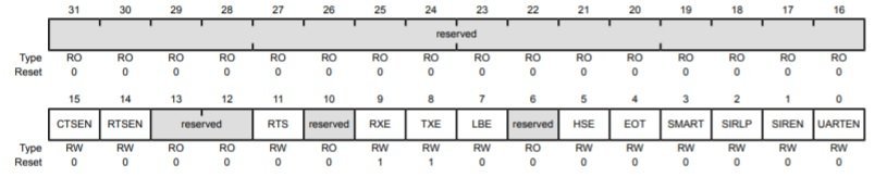
For example, you can to enable UART2 module of TM4C123 MCU, you can enable UART2 by setting UARTEN, RXE and TXE bits of UARTCTL register like this:
UART02->CTL = 0x301; /* enable UART2, TXE, RXE */TM4C123 UART Line Control (UARTLCRH)
This register is used to define the format of UART data frame such as number of bits data, data length (bits 5 and 6) , parity bit and stop bits implementation, FIFO enable.disable and break conditions, etc.
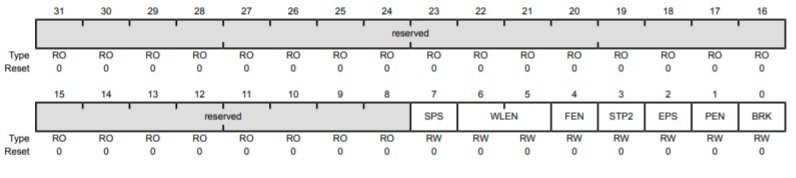
| Bit | Name | Function |
|---|---|---|
| 0 | Send Break | When set to 1, a logic low signal is generated on the UART Tx line. For the proper generation of break conditions, the software should set this bit to 1 for at least a duration of two UART frames. |
| 1 | Parity Enable | To enable generation and checking of parity, this bit field should be set to1 |
| 2 | Even Parity | Setting to 1 enables even parity, which generates and checks for even num- ber of l’s in the data and parity bits during transmission and reception. |
| 3 | Stop bits | When this bit is cleared to 0, one stop bit is transmitted at the end of UART frame. Setting it to I transmits two stop bits. |
| 4 | FIFO Enable | This bit enables or disables FIFO buffers. When cleared to the FIFOs are disabled. |
| 5 | Word length | The word length bit field configures the number of data bits transmitted or received in a UART frame. A value of 0, 1, 2 or 3 configures the data length equal to 5. 6, 7 or 8 bits in the UART frame. |
| 6 | Stick Parity | This bit field enables or disables the stick parity. When this bit is set and bits 1 and 2 of this register are also set to 1 then parity bit is transmitted and checked as 0. If bit 1 is set and bit 2 is cleared then parity bit is transmitted and checked as 1. |
For example, this line sets the data length of UART2 format to 8-bit, no-parity bit, disable FIFO and one stop bit,
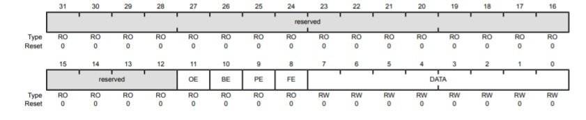
UART2->LCRH = 0x60; /* 8-bit, no parity, 1-stop bit, no FIFO */Data Register ( UARTDR )
This register for both transmitter and receiver modules. This is also a 32-bit register. First, 0 to 7 bits contain the data that we want to transmit or data that is received on an Rx pin of TM4C123G microcontroller. Bits 8-11 provides error information such as framing error, parity error, break error, and overrun error.
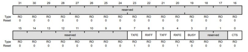
UART Flag/status Register (UARTFR) register provides flag bits such as transmit FIFO empty/Full, receive FIFO full/empty, etc.
TM4C123 Tiva C UART Transmitter Programming
In this section, we will learn to configure the UART transmit module of TM4C123 microcontroller and at the end, we will provide an example code to transmit data, by using the UART2 module, from the Tiva C launchpad to the computer.
Steps to Configure Transmitter
Following these steps to configure UART serial ports registers:
- Enable clock signal to the selected UART module using related enable bit of RCGCUART register.
- After that enable clock signal to GPIO pins of Rx and Tx pins by using the RCGCGPIO register.
- Before configuring the selected UART port, disable it by writing zero to the UARTCTL register.
- Calculate baud divisor value by using the required baud rate and clock frequency and write integer and fractional part of baud divisor to UARTIBRD and UARTFBRG registers respectively.
- Select the system clock for UART by writing 1 to UARTCC register.
- Configure the line control register by enabling or disabling different bits such as stop bit, parity, data length, interrupt, and FIFO.
- Enable TxE and RxE bits of UARTCTL to enable transmitter and receiver.
- Enable UART port by setting UARTEN bit of UARTCTL register.
- In the end, configure the alternate function of GPIO pins using the port control register (UARTPCTL).
TM4C123 Tiva C UART Transmitter Code
This program transmits “HELLO” through the UART5 module of TM4C123GH6PM microcontroller. PE5 pin of Tiva C is used as a TX5 pin.
If you want to see the output of this code, you can connect the TX5 pin of the launchpad with the computer using an FTDI ( USB to serial converter) and use a hyper terminal or putty to see the output.
#include "TM4C123.h"
void Delay(unsigned long counter);
char UART5_Receiver(void);
void UART5_Transmitter(char data);
int main(void)
{
	  SYSCTL->RCGCUART |= 0x20;  /* enable clock to UART5 */
    SYSCTL->RCGCGPIO |= 0x10;  /* enable clock to PORTE for PE4/Rx and RE5/Tx */
    Delay(1);
    /* UART0 initialization */
    UART5->CTL = 0;         /* UART5 module disbable */
    UART5->IBRD = 104;      /* for 9600 baud rate, integer = 104 */
    UART5->FBRD = 11;       /* for 9600 baud rate, fractional = 11*/
    UART5->CC = 0;          /*select system clock*/
    UART5->LCRH = 0x60;     /* data lenght 8-bit, not parity bit, no FIFO */
    UART5->CTL = 0x301;     /* Enable UART5 module, Rx and Tx */

    /* UART5 TX5 and RX5 use PE4 and PE5. Configure them digital and enable alternate function */
    GPIOE->DEN = 0x30;      /* set PE4 and PE5 as digital */
    GPIOE->AFSEL = 0x30;    /* Use PE4,PE5 alternate function */
    GPIOE->AMSEL = 0;    /* Turn off analg function*/
    GPIOE->PCTL = 0x00110000;     /* configure PE4 and PE5 for UART */

	  Delay(1);

	while(1)
	{
		UART5_Transmitter('H');
                UART5_Transmitter('E');
                UART5_Transmitter('L');
                UART5_Transmitter('L');
                UART5_Transmitter('O');
                UART5_Transmitter('\n');
	}
}


void UART5_Transmitter(char data)
{
    while((UART5->FR & 0x20) != 0); /* wait until Tx buffer not full */
    UART5->DR = data;                  /* before giving it another byte */
}

void Delay(unsigned long counter)
{
	unsigned long i = 0;

	for(i=0; i< counter; i++);
}
TM4C123 Tiva C UART Receiver Programming
In the last section, we have learned to configure the receiver module of UART5. The steps to configure the receiver part of UART5 are exactly the same except the RXFE flag of the UART flag register.
RXFE bit becomes low when the receive buffer is not empty. In other words, when data is available to read. Therefore, in UART5_Receive() function, we monitor the RXFE bit of the UARTFR register, whenever it goes low, we read the data from UARTDATA register.
Tiva C UART Receiver Code
This code reads data from RX5 pin whenever data is available and echo back data through TX5 pin.
#include "TM4C123.h"
#include <stdint.h>
#include <stdlib.h>
void Delay(unsigned long counter);
char UART5_Receiver(void);
void UART5_Transmitter(unsigned char data);
void printstring(char *str);
int main(void)
{
	  SYSCTL->RCGCUART |= 0x20;  /* enable clock to UART5 */
    SYSCTL->RCGCGPIO |= 0x10;  /* enable clock to PORTE for PE4/Rx and RE5/Tx */
    Delay(1);
    /* UART0 initialization */
    UART5->CTL = 0;         /* UART5 module disbable */
    UART5->IBRD = 104;      /* for 9600 baud rate, integer = 104 */
    UART5->FBRD = 11;       /* for 9600 baud rate, fractional = 11*/
    UART5->CC = 0;          /*select system clock*/
    UART5->LCRH = 0x60;     /* data lenght 8-bit, not parity bit, no FIFO */
    UART5->CTL = 0x301;     /* Enable UART5 module, Rx and Tx */

    /* UART5 TX5 and RX5 use PE4 and PE5. Configure them digital and enable alternate function */
    GPIOE->DEN = 0x30;      /* set PE4 and PE5 as digital */
    GPIOE->AFSEL = 0x30;    /* Use PE4,PE5 alternate function */
    GPIOE->AMSEL = 0;    /* Turn off analg function*/
    GPIOE->PCTL = 0x00110000;     /* configure PE4 and PE5 for UART */

	  Delay(1);
	printstring("Hello World \n");
	Delay(10);
	while(1)
	{
		char c = UART5_Receiver();          /* get a character from UART5 */
		UART5_Transmitter(c);
	}
}

char UART5_Receiver(void)
{
    char data;
	  while((UART5->FR & (1<<4)) != 0); /* wait until Rx buffer is not full */
    data = UART5->DR ;  	/* before giving it another byte */
    return (unsigned char) data;
}

void UART5_Transmitter(unsigned char data)
{
    while((UART5->FR & (1<<5)) != 0); /* wait until Tx buffer not full */
    UART5->DR = data;                  /* before giving it another byte */
}

void printstring(char *str)
{
  while(*str)
	{
		UART5_Transmitter(*(str++));
	}
}

void Delay(unsigned long counter)
{
	unsigned long i = 0;

	for(i=0; i< counter; i++);
}
void SystemInit(void)
{
    __disable_irq();    /* disable all IRQs */

    /* Grant coprocessor access */
    /* This is required since TM4C123G has a floating point coprocessor */
    SCB->CPACR |= 0x00F00000;
}
Keil uvision v5 Instructions
Note: If you are using Keil uvision v5, you should remove the void SystemInit(void) function from the above code. Because the startup file in Keil v5 already contains the function SystemInit().
After that follow these steps to build above code with Keil uvision 5:
The other issue with the SystemInit() function in the new system_TM4C123.c is that it configures the clock generation which results in a different system clock rate than the default 16 MHz frequency. But the above sample code works on the default 16 MHz system clock. Therefore, the above program creates timing issues with Keil v5. You may retain the default system clock rate in Keil v5, by the following steps:
- Expand the Project->Device to show system_TM4C123.c (startup)
- Double click to open the file in the editor window
- Find the line “#define CLOCK_SETUP 1” as the figure below
- Comment out the line
- Rebuild the project

Tiva UART Communication between PC and Tiva C
Now let’s see the demo of the above code. In order to see the output of the above program, you will need an FTDI cable that is serial to USB converter. You will need an FTDI cable like this:
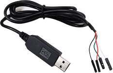
This table shows the pin connection of FTDI cable:
| Pin name | Pin color |
|---|---|
| Tx | Green |
| Rx | White |
| Ground | Black |
| 5 volt | Red |
When you connect this USB to serial converter cable with your computer, it will automatically install its drivers. But if your computer is not able to install drives automatically, you can download drivers from this link.
You will also need a serial terminal on your computer such as hyper terminal or putty. Go to this link and download Putty. After downloading, install it on your personal computer.
Now upload the above code to TM4C123 Tiva LaunchPad. After that make connections with TM4C123 and FTDI cable according to this table:
| TM4C123 | FTDI Cable |
|---|---|
| TX5/PE5 | RXD (white cable) |
| RX5/PE4 | TXD (green cable) |
| GND | GND (black cable) |

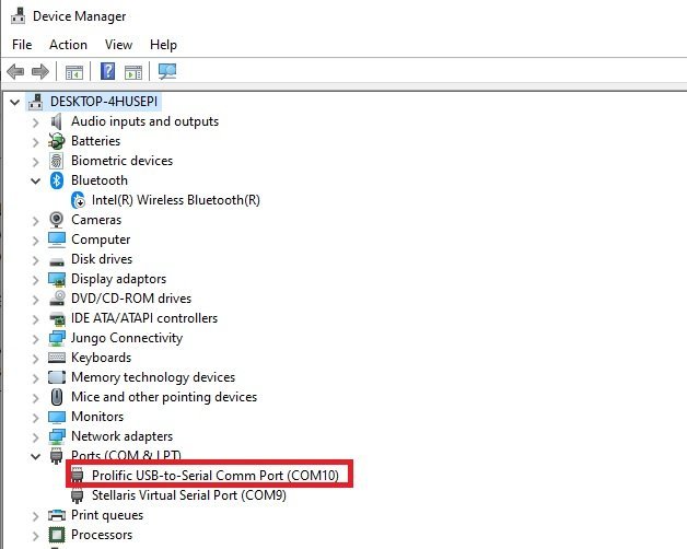
After that open putty terminal. Enter baud rate of 9600 and write COM pin to which your FTDI cable is connected with computer. In order to find COM pin number, you can go to device manager and note down COM pin number as shown below:
Now open the putty terminal and make settings according to this figure and click on open.
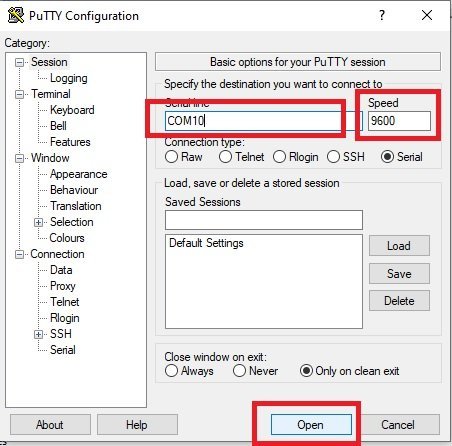
Now clock on reset button of TM4C123 tiva c, you will get “Hello World” string output on putty terminal and also whatever, you will type on the terminal will echo back to the terminal.

Other UART Tutorials:
i don’t Understand which code did we put in the video and tried The transmission or the receiver code or both . i can’t understand it well for example if i have a gps and a tiva c do i need a transmission code or not ? and if i need why would i need it ? i don’t think the gps would need anydata from the tiva c
If you only want to receive data from GPS, you will need to need to connect the Tx pin of GPS with the Rx pin of TM4C123. But if your GPS requires an configuration settings to be sent from TM4C123 then you will need to connect transmission pin also.
UART1 can be PB0 and PB1 too. There are multiple I/O choices for some of the UARTs. Just for the record.
Yes, you are right and we have not mentioned that in the table to keep the tutorial simple and not to confuse beginners.
Hi and thank you for all this. I am unsure of how to organize the project in Keil. Where does the transmitter code go and where does the receiver code go. They both have a main. So far I have only been able to compile the transmitter code and I can type letters to the Putty terminal.
Nice tutorials! However, I didn’t find code download link.